Delta EV Ultra User manual

www.deltapowersolutions.com
Installation manual
EV Ultra Fast Charger


EV Ultra Fast Charger Table of contents
Table of contents
1Change logs...................................................................................................................2
2Important safety and grounding instructions..................................................................3
2.1 Safety and compliance........................................................................................3
2.2 Grounding instructions ........................................................................................3
3Before installation ..........................................................................................................4
3.1 Safety requirements ............................................................................................4
3.2 Recommended tools............................................................................................4
3.3 Important safety instructions ...............................................................................4
4Site preparation .............................................................................................................5
4.1 Power connection................................................................................................5
4.1.1 Circuit breaker rating and cable cross section......................................5
4.1.2 Required cable length...........................................................................6
4.2 LAN cabling.........................................................................................................7
4.3 Load-management connection............................................................................7
4.4 Load-management cabling..................................................................................7
4.5 Required distances and dimensions ...................................................................8
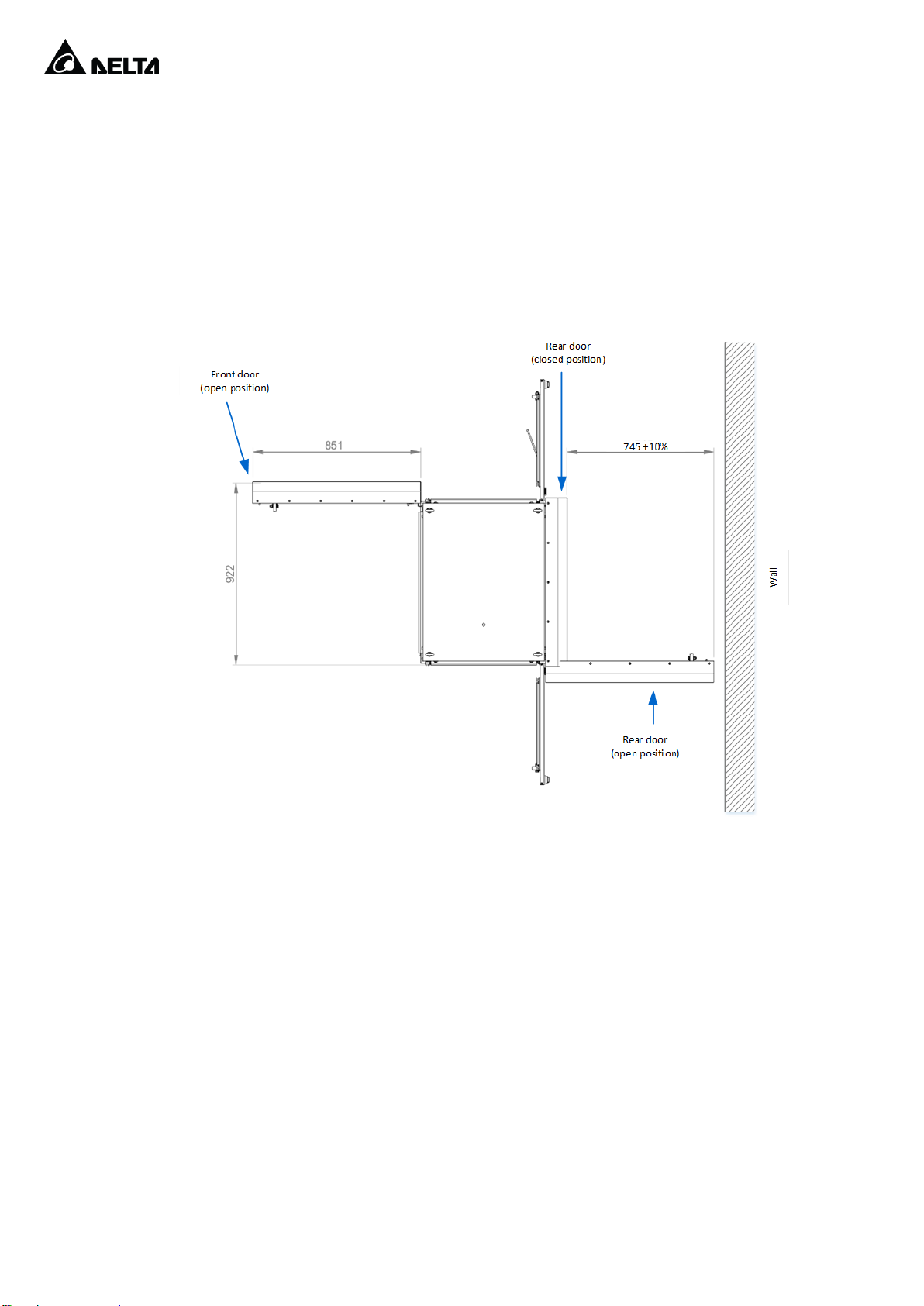
4.5.1 Wall distance.........................................................................................8
4.5.2 Collision protection pole........................................................................9
4.5.3 Cable entry..........................................................................................10
5Preparing for the installation........................................................................................12
6Commissioning............................................................................................................17
7Load-management connection installation..................................................................18
8Application guidance lightning protection....................................................................21
9Network connection.....................................................................................................22
9.1 Sites with 1 EV Ultra Fast Charger....................................................................22
9.1.1 Ethernet connection............................................................................22
9.1.2 Wireless connection............................................................................23
9.2 Sites with more EV Ultra Fast Chargers............................................................24

2
EV Ultra Fast Charger Change logs
1 Change logs
Change logs for this document:
Date
Document
version
Responsible
Changes
26.10.2018
3.0
MKLs
Included change log
2.11.2018
3.1
MKLs
Added clarification for IP connection
29.11.2018
3.2
MKLs
Updated circuit breaker rating and cable
cross section according to IEC 60364-5-
52:2011
03.04.2019
3.3
MKLs
Updated connection diagram - load-
management connection box

EV Ultra Fast Charger Important safety and grounding instructions
3
2 Important safety and grounding instructions
2.1 Safety and compliance
Read the manual before installation or usage of device.
Do not put tools, material or body parts into the electric vehicle connector.
Do not use the EV Ultra fast charger if the chassis, power cord or charging cable are frayed, have
broken insulation, or any other signs of damaged.
Do not install or use the Ultra fast charger if the enclosure is broken, cracked, open or has any other
indications of damage.
The EV Ultra fast charger should be installed only by a qualified technician.
To maintain environmental control of device, EV Ultra fast charger should be powered up
immediately after installation.
Make sure that the materials used and the installation procedures follow local building codes and
safety standards.
The information provided in this manual in no way exempts the user of responsibility to follow all
applicable codes or safety standards.
The manufacturer is not responsible for physical injury, damage to property or equipment caused by
the installation of this device.
This document provides instructions for the EV Ultra fast charger and should not be used for any
other product. Before installation or use of this product, you should review this manual carefully and
consult with a licensed contractor, licensed electrician, or trained installation expert to make sure of
compliance with local building codes and safety standards.
2.2 Grounding instructions
An equipment grounding conductor or a grounded, metal, and permanent wiring system is required for the
EV Ultra fast charger connection. This should be run with circuit conductors and connected to the equipment
grounding bar or lead on the EV Ultra fast charger.

4
EV Ultra Fast Charger Before installation
3 Before installation
3.1 Safety requirements
Be sure to preview the standard operating procedures (SOP) and ensure local building and electrical codes
are reviewed before installing the EV Ultra fast charger.
The EV Ultra fast charger should be installed by a trained technician according to the instruction manual and
local safety regulations.
Use appropriate protection when connecting to the main power distribution cable.
3.2 Recommended tools
The following tools are recommended for the EV Ultra fast charger installation:
- (1x) No.2 Philips screw driver
- M10 hexagon screw (optional for OPI2020)
- M10 flat washer (optional for OPI2020)
- M10 or M12 expansion bolts
- (1x) concrete drill
- (1x) wire cutters
- (1x) 17mm ratcheting wrench for the base
- (1x) RJ45 crimping tool
- RJ45 connectors
3.3 Important safety instructions
Save these Instructions.
The EV Ultra fast charger should be installed only by a licensed contractor, and/or a licensed
electrician in accordance with all applicable state, local and national electrical codes and
standards.
Before installing the EV Ultra fast charger, review this manual carefully and consult with a
licensed contractor, licensed electrician and trained installation expert to ensure compliance
with local building practices, climate conditions, safety standards, and state and local codes.
Warning! Danger of electrical shock or injury. Turn OFF power at the panel board or load center
before working inside the equipment or removing any component. Do not remove circuit protective
devices or any other component until the power is turned OFF.
Caution! TO AVOID DAMAGE TO THE CHARGER OR PERSONAL INJURY, MAKE SURE THE
INSTALLATION LOCATION IS ABLE TO SUPPORT THE WEIGHT OF THE ULTRA FAST
CHARGER.

EV Ultra Fast Charger Site preparation
5
4 Site preparation
4.1 Power connection
EV Ultra Fast Charger should be connected to 3 phase power line (L, N, PE) with appropriate copper cable.
Device should be protected with dedicated circuit breaker.
Follow below chapters to identify and prepare site for EV Ultra Fast Charger installation.
EV Ultra Fast Charger is equipped with RCD breakers for AC output (AC Type 2 plug, AC Type 2 socket).
To maintain environmental control of device, EV Ultra fast charger should be powered up immediately after
installation. Not powered EV Ultra fast charger may be damaged due to improper environmental conditions.
4.1.1 Circuit breaker rating and cable cross section
The tables below points the recommended fusing and cable cross section. The site planning process must
count with local regulations and codes, exact fusing, cable type and manufacturer. It is recommended to ask
Delta customer service in case of use different ratings. Delta is not responsible for oversizing or undersizing
of cabling and protection.
The maximal AC current is the current draw by charger in case that grid voltage in place of installation is on
lowest allowed limit. Charger operating voltage is 230V/400V±10%, thus lowest voltage limit is 207V/360V.
As the charger is configurable in terms of power steps and charging points, different configuration results in
different charger consumption. To calculate consumption use following general equation:
𝐼𝑛𝑜𝑚 = 𝑞𝑡𝑦 𝑜𝑓 𝑚𝑜𝑑𝑢𝑙𝑒𝑠 × 𝑚𝑜𝑑𝑢𝑙𝑒 𝑛𝑜𝑚𝑖𝑛𝑎𝑙 𝑐𝑢𝑟𝑟𝑒𝑛𝑡 + 𝐴𝐶 𝑠𝑜𝑐𝑘𝑒𝑡 𝑐𝑢𝑟𝑟𝑒𝑛𝑡 + 𝐴𝐶 𝑝𝑙𝑢𝑔 𝑐𝑢𝑟𝑟𝑒𝑛𝑡 + ℎ𝑎𝑙𝑓 𝑐𝑜𝑜𝑙𝑖𝑛𝑔 𝑐𝑢𝑟𝑟𝑒𝑛𝑡
𝐼𝑚𝑎𝑥 = 𝑞𝑡𝑦 𝑜𝑓 𝑚𝑜𝑑𝑢𝑙𝑒𝑠 × 𝑚𝑜𝑑𝑢𝑙𝑒 𝑚𝑎𝑥𝑖𝑚𝑎𝑙 𝑐𝑢𝑟𝑟𝑒𝑛𝑡 + 𝐴𝐶 𝑠𝑜𝑐𝑘𝑒𝑡 𝑐𝑢𝑟𝑟𝑒𝑛𝑡 + 𝐴𝐶 𝑝𝑙𝑢𝑔 𝑐𝑢𝑟𝑟𝑒𝑛𝑡 + 𝑓𝑢𝑙𝑙 𝑐𝑜𝑜𝑙𝑖𝑛𝑔 𝑐𝑢𝑟𝑟𝑒𝑛𝑡
𝑚𝑜𝑑𝑢𝑙𝑒 𝑛𝑜𝑚𝑖𝑛𝑎𝑙 𝑐𝑢𝑟𝑟𝑒𝑛𝑡 = 19,29𝐴, 𝑚𝑜𝑑𝑢𝑙𝑒 𝑚𝑎𝑥𝑖𝑚𝑎𝑙 𝑐𝑢𝑟𝑟𝑒𝑛𝑡 = 21,43𝐴,
𝐴𝐶 𝑠𝑜𝑐𝑘𝑒𝑡 𝑐𝑢𝑟𝑟𝑒𝑛𝑡 = 32𝐴, 𝐴𝐶 𝑝𝑙𝑢𝑔 𝑐𝑢𝑟𝑟𝑒𝑛𝑡 = 63𝐴
ℎ𝑎𝑙𝑓 𝑐𝑜𝑜𝑙𝑖𝑛𝑔 𝑐𝑢𝑟𝑟𝑒𝑛𝑡 = 1𝐴, 𝑓𝑢𝑙𝑙 𝑐𝑜𝑜𝑙𝑖𝑛𝑔 𝑐𝑢𝑟𝑟𝑒𝑛𝑡 = 2𝐴
Example of calculation for charger with 100kW DC charge capacity, 22kW AC and 43kW AC charge capacity:
𝐼𝑛𝑜𝑚 = 8 × 19,29 +32 +63 + 1 = 250 𝐴
𝐼𝑚𝑎𝑥 = 8 × 21,43 +32 +63 + 2 = 268 𝐴

6
EV Ultra Fast Charger Site preparation
Example of calculation for charger with 150kW DC charge capacity, 22kW AC and 43kW AC charge capacity:
𝐼𝑛𝑜𝑚 = 12 ×19,29 +32 +63 + 1 = 327 𝐴
𝐼𝑚𝑎𝑥 = 12 ×21,43 +32 +63 + 2 = 354 𝐴
Note! Charger controller will limit Imax current to 336A.
The recommended minimal cable cross section accepted by charger terminals is 95mm2. The maximal cable
cross section accepted by terminals is 300mm2. Site planning needs to check if the cable diameter and
bending radius is suitable for cable glands and plinth dimensions.
Use of aluminium cable is prohibited. The charger is cyclic load resulting to cycling thermal expansion and
contraction of cables. This increase risk of hotspots. During annual maintenance, check the cable connection
in charger and also in distribution board.
Available AC connection –current rating for EV QC with DC plugs, AC 22kW.
Available AC connection –current rating for EV QC with DC plugs, AC 43kW.
Available AC connection –current rating for EV QC with DC plugs, AC 43kW and AC 22 kW.
Note! Cable cross section is based on IEC 60364-5-52:2011 standard (Cu conductor, multi-core
cable, 3 live cores, PVC insulation, in the earth –D2 case). Site specific conditions must be taken
into account for proper dimensioning. For different types of cables and installation conditions please
refer to cable fact sheet or consult with Delta customer service.
4.1.2 Required cable length
Installation site should be prepared with AC cabling to supply L1, L2, L3, N, PE. Cable length should be at
least 1,5 meter long from base. Cable should be prepared inside the footprint of the EV quick Charger. Check
exact cable location in chapter 4.5.3
DC charge capacity [kW]
50
110kW platform
150kW platform
Maximal AC current [A]
120
227
291
Fuse rating in AC distribution [A]
125
250
315
Cable cross section (Cu) [mm2]
95
185
240
DC charge capacity [kW]
50
110kW platform
150kW platform
Maximal AC current [A]
151
258
322
Fuse rating in AC distribution [A]
160
315
355
Cable cross section (Cu) [mm2]
95
240
300
DC charge capacity [kW]
50
110kW platform
150kW platform
Maximal AC current [A]
183
290
354
Fuse rating in AC distribution [A]
200
315
355
Cable cross section (Cu) [mm2]
120
240
300

EV Ultra Fast Charger Site preparation
7
4.2 LAN cabling
Installation site should be prepared with gel outdoor CAT5e Ethernet LAN cable. Cable should be crimped
with RJ45 connector following Ethernet standard.
Required Ethernet cable length is 2 meters long.
oEthernet 2m
Cable should be prepared inside the footprint of the EV quick Charger. Check exact cable location in chapter
4.5.3
4.3 Load-management connection
Installation of the load-management equipment should be allowed in power meter room.
oIn close distance to power meter
oBox size ~20x40x30cm (D x W x H)
oAC power supply available
Cable connection distance between power meter room and EVC should not exceed 250m
4.4 Load-management cabling
Installation site should be prepared with outdoor CAT5e gel outdoor CAT5e cable. Required cable length is 2
meters long.
oEthernet 2m
Cable should be prepared inside the footprint of the EV quick Charger. Check exact cable location in chapter
4.5.3
Cable distance between power meter room and EVC should not exceed 250m

8
EV Ultra Fast Charger Site preparation
4.5 Required distances and dimensions
4.5.1 Wall distance
Device is equipped with door on every side. Therefore it cannot be installed close to obstacles that could
limit access to EV Ultra Fast Charger. Safe distance between closed unit and wall that allows to open rear
door is approx. 820 mm.
Figure 1 Wall distance

EV Ultra Fast Charger Site preparation
9
4.5.2 Collision protection pole
EV Ultra Fast Charger can be protected against accidental damages by protection poles installed in front of
device. Available space for installation is limited due to required maintenance tasks and necessity to access
device. Position of collision protection pole is marked in green zone below.
Figure 2 Collision protection pole install zone

10
EV Ultra Fast Charger Site preparation
4.5.3 Cable entry
EV Ultra Fast Charger should be connected with cables entering from the bottom of the device. Plinth is
equipped with dedicated cable glands. Dimensions of the cable entry are visible in pictures below.
Cable should be prepared inside the footprint of the EV quick Charger. Picture below shows dimensions of
the plinth and cable entry. Notice plinth dimensions are different than overall footprint.
Exact cable location should be inside green color marked zone.
Figure 3 Cable entry zone –top view

EV Ultra Fast Charger Site preparation
11
Figure 4 Cable entry zone –front view

12
EV Ultra Fast Charger Preparing for the installation
5 Preparing for the installation
Prepare the concrete base for EV Ultra fast charger according to the figure below. The
dimensions of the concrete base should allow installation of the cabinet’s plinth on it
(external size c.a.
W 825 x D 650).
Figure 5 Installation dimensions –top view

EV Ultra Fast Charger Preparing for the installation
13
Figure 6 Installation dimensions –AC connections
Prepare holes for 4 x M10 Anchor bolts.
Remove plinth hatches seen in figure below.
Figure 7 Remove plinth hatches
Terminal block L1, L2, L3
Terminal block N
Terminal block PE

14
EV Ultra Fast Charger Preparing for the installation
Lift the charger up and put on concrete.
Figure 8 Lifting cabinets by crane
Fix the anchors with nuts.
Provide cables to distribution through cable glands bottom plate.
Open the main fuses.
Figure 9 Main fuses

EV Ultra Fast Charger Preparing for the installation
15
Connect the LAN cable if applicable. (Please refer to chapter 9.1.1 for detailed description.)
For wireless connection, install SIM card in the modem. (Please refer to chapter 9.1.2 for
detailed description.)
Note! If Ultra Fast Charger is equipped with Proxy system with DEEMS, then the SIM card –back
office connection, is in the RUT955 device (please, refer to Figure 17).
Figure 10 SIM card and LAN cable
Connect the AC cables with a 30 Nm torque: first P connection, second Neutral, third three
lines. The cable size must be 300 mm² diameters at maximum. The maximum current and
cable cross section are defined upon system configuration and local regulations.
Note! 300 Arms required for maximum system configuration.

16
EV Ultra Fast Charger Preparing for the installation
Perform a visual and mechanical inspection especially to the cables, guns and user
interface to make sure they are not damaged.
Remove the eyebolts after installation. Plug the eyebolt holes with provided plugging bolts.
See figure below.
Figure 11 Lifting eyebolts
Make sure plastic cushion protecting power modules are removed from all shelves.

EV Ultra Fast Charger Commissioning
17
6 Commissioning
Make sure that the control power breaker is open and that all power module breakers and RCDs
are closed.
Figure 12 Control power breaker open
Close main fuses.
Close the control power breaker.
Fix cabinet hatches back again.

18
EV Ultra Fast Charger Load-management connection installation
7 Load-management connection installation
Solution with power management can be subject of further adjustments and changes even though principle
of the connection remains unchanged.
Fix load-management connection box in the power meter room.
Connect signalling device of kWh impulses port S0+ to port DI0 of ioLogic R1212 device.
Connect signalling device of kWh impulses port S0- to GND bat inside load-management
connection box.
Connect signalling device of 15 min intervals port S0+ to port DI1of ioLogic R1212 device
Connect signalling device of 15 min intervals port S0- to GND bar inside load-management
connection box.
Connect data+ cable to RS485 port D1+ and data- cable to port D1- of of ioLogic R1212
device.
Use outdoor type, CAT5e cable, and route it to the EVC to terminate connection.
Make sure 120Ohm resistor is fixed on RS485 port between D1+ and D1-.
Figure 13 Connection points
Caution! Make documentation which colour wires were used on RS485 terminal of ioLogic R1212
device. It is important for proper connection establishing in commissioning stage.
Table of contents
Other Delta Automobile Accessories manuals
Popular Automobile Accessories manuals by other brands

Comelit
Comelit KCA2074 Technical manual

WAGNER TUNING
WAGNER TUNING 400001003 Installation instruction

LAS
LAS BC260 operating instructions

Whispbar
Whispbar K678W Fitting instructions

ECS Electronics
ECS Electronics CT-052-D1 Fitting instructions electric wiring

Metra Electronics
Metra Electronics 99-7503 installation instructions

Kuda-Phonebase
Kuda-Phonebase 5460 Installation instruction

mft
mft BackCarrier instruction manual

Classic Accessories
Classic Accessories Over Drive PermaPro instructions

iOttie
iOttie Easy One Touch 4 manual

Discount Car Stereo
Discount Car Stereo A2DIY-C5 quick start

Amit
Amit VHG760AM-0T001 Quick installation guide