hc-cargo 160775 User manual
160775
1
SUPER 7" 4+1 REAR VIEW CAMERA AND MULTIMEDIA KIT
SUPER 7” 4+1 Rückfahr-Kamera mit Multimedia Satz
SYSTÈME D’OBSERVATION 7” 4+1 ET KIT MULTIMEDIA
SUPER 7” 4+1 REAR VIEW CAMERA AND MULTIMEDIA KIT
SUPER 7” 4+1 BAKKAMERA OG MULTIMEDIESÆT
SYSTEM OBSERWACJI PRZESTRZENI Z TYŁU POJAZDU
USER MANUAL, page 2
Vedpak 98_Version 6_12.2017
BEDIENUNGSANLEITUNG, page 17
MANUALE D’USO, page 47
MANUEL D’UTILISATION, page 32
BETJENINGSVEJLEDNING, side 63
INSTRUKCJA OBSŁUGI, side 78

2Vedpak 98_Version 6_12.2017
160775
CONTENT:
Features .......................................................................3
Installation of monitor.......................................................3
Signal cable description .....................................................3
Control cable description ...................................................4
Front panel control ..........................................................5
OSD menu - Screen menu ...................................................6
Display .........................................................................7
Mirror function................................................................8
Camera.........................................................................8
Factory default settings.....................................................10
Cam out........................................................................ 10
Exit OSD........................................................................10
Installation of camera .......................................................11
Setting of distance gauges ..................................................12
Monitorspecications .......................................................13
Cameraspecications .......................................................15
Accessories ....................................................................16
PACKAGE CONTENTS:
1. 7" LED monitor 16:9.
2. Sun-hood.
3. Mounting brackets.
4. Mounting parts.
5. Control cable.
6. Camera w/ infrared LED’s and built-in microphone.
7. 20 mtr. camera cable.
8. User manual.
CAUTION:
Do not add any parts or use any accessories which are not
provided from the manufacturer.
Do not adjust settings while driving, due to risk of accidents.
Do not apply pressure to the screen.
Do not use any liquid to clean the monitor. If you need to
clean it, please use a LCD cleaning cloth.

3
Vedpak 98_Version 6_12.2017
160775
FEATURES:
Advanced OSD Menu for easy use
Supports up to 4 CCD Camera inputs (6 pin Mini DIN).
Extra RCA input for multimedia (VCD, DVD, Game device).
Provide 2 Video / 1 Audio signal output.
Support Single / Dual / Triple / Quad Screen (Cam out)
Signal Trigger for Rear / Left / Right / AV.
OSD control for Individual Normal / Mirror Camera Image.
Auto Day and Night control via photo diode sensor.
Auto Detection for NTSC / PAL System.
Supported 9.6V~32V Car power system working
Professional Metal Case with Anti Shocking Design
INSTALLATION OF MONITOR:
1. Check the package and make sure all parts are included.
2. Clip the sun-hood on to the monitor and make sure it is installed properly.
3. Install the monitor on to the bracket.
4. Adjust the monitor to an appropriate / comfortable viewing angle before tightening the screws.
5. Connect the control cable to the power socket which is located at the rear side of the monitor.
6. Monitor installation is now completed. Each control cable wire is attached with a sticker to indicate its signal
function.
SIGNAL CABLE DESCRIPTION:
1. Cam-R (Mini DIN).
For rear vision camera connection.
(Selection of CAM-R overrides selections of other cameras).
2. Cam-A.
For 2nd camera connection.
3. Cam-B.
For 3nd camera connection.
4. Cam-C.
For 4rd camera connection.
5. Live Video Out (RCA - White wire).
On screen video loop out (for recording, second monitor or other device.
6. Live Audio Out (RCA - Black wire).
On screen video loop out (for recording, second monitor or other device.
7. AV VIDEO IN (RCA - Yellow wire).
Connection for any Video signal DVD, VCD, Game, camera.
8. AV AUDIO IN (RCA - Red wire).
Connection for any Audio signal DVD, VCD, game.
9. CAM OUT (RCA - Green wire).
Video loop (for recording, second monitor or other device)
Set up by OSD under CAMERA set up window.
4Vedpak 98_Version 6_12.2017
160775
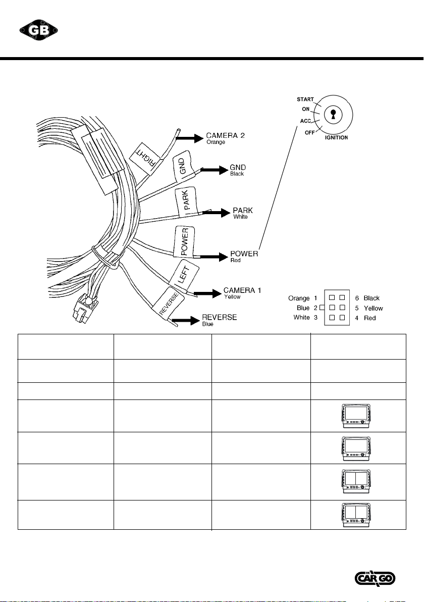
CONTROLCABLE DESCRIPTION:
Cableconguration
WIRE COLOUR
Red
Black
White
Blue
Orange
Yellow
FUNCTION
Acc power
(DC 9.6-DC32V.)
GND
Parking control
Reverse control
Camera 2
Camera 1
REMARKS
Active GND
Active Power Level.
Connect to reverse light.
Active Power Level.
Connect to direction
light (R).
Active Power Level.
Connect to direction
light (L).
ON SCREEN VIEW
1. Activation of the trigger cables for reverse, right or left overrides any selection of images and shows the
triggered camera.
2. *When pull the hand break, user need to press SOURCE button again to display AV IN picture.
Don’t connect the red wire
(power wire) of this product
directly to the battery.
Connect the red wire of this
product to the ACC of the
ignition key switch. Failure to
do so may result in permanent
damage of the product.
4 5 Vedpak 98UK_Version 5_010909
160775
GB
CONTROLCABLE DESCRIPTION:
Cable configuration
WIRE COLOUR
Red
Black
White
Blue
Orange
Yellow
FUNCTION
Acc power
(DC 9.6-DC32V.)
GND
Parking control
Reverse control
Camera 2
Camera 1
REMARKS
Active GND
Active Power Level.
Connect to reverse light.
Active Power Level.
Connect to direction
light (R).
Active Power Level.
Connect to direction
light (L).
ON SCREEN VIEW
1. Activation of the trigger cables for reverse, right or left overrides any selection of images and shows the triggered camera.
2. *When pull the hand break, user need to press SOURCE button again to display AV IN picture.
Don’t connect the red wire
(power wire) of this product
directly to the battery. Connect
the red wire of this product
to the ACC of the ignition key
switch. Failure to do so may
result in permanent damage of
the product.
Jump So urc e Po wer
M e nu
AV
Jump S ourc e Power
M e nu
CAM R
CAM R CAM B
CAM A C AM R
Jump Sourc e rewoP
M en u
AV
Jum p Source Power
M enu
CAM R
CAM R CAM B
CAM A CA M R

5
Vedpak 98_Version 6_12.2017
160775
FRONT PANEL CONTROL:
POWER: Press the POWER button to activate the monitor or to keep the monitor under stand by mode.
SOURCE: Press this button to select image sequence
CAM ACAM BCAM CCAM R CAM A+B CAM C+R
CAM A+RCAM R+BCAM A+CCAM C+B CAM R/AB
CAM R+ABCAM A……
With activated hand break, press this button to select image sequence
AVCAM A+BCAM C+RCAM A+RCAM R+BCAM A+C
CAM C+BCAM R/ABCAM R+ABCAM ACAM BCAM CCAM R AV……..
JUMP: Pressthisbuttontodisplaydenedcamerainput,usercanselect
QUADSEQCAM A+BCAM C+RCAM A+RCAM R+B
CAM A+CCAM C+BCAM R/AB CAM R+AB CAM A CAM B
CAM CCAM R via OSD as default value.
MENU: This encoder switch provides the following function:
1. Activate OSD menu:
Press the menuswitch to activate the OSD menu. After the OSD menu is activated, in case
theuserdoesnotproceedforfurthersetup,theOSDmenuwillthenautomaticallyturno
within 20 seconds.
2. Enter-function:
Press the encode switch to act as "Enter" Functions under the OSD menu.
3. Volume level:
Exit the OSD menu: user can turn this switch left or right to adjust the volume value.

6Vedpak 98_Version 6_12.2017
160775
OSD MENU:
1. Press the MENU button to enter the OSD Menu.
2. Turn the MENU button left or right to select the setting you wish to proceed.
The colour of the content will turn yellow to identify your selection.
3. Press the MENU button again until the colour of the content turns from yellow to red to
enter system settings.
Turn the MENU button left or right to adjust your setting value.
DISPLAY
OSD DISPLAY
CAMERA
RECALL
EXIT
SCREEN Menu
ThismenusetupcontainsdierentsettingfortheTFTLCD.
Brightness
Provide adjustment for shade and brightness level of TFT display.
Setting value from 0 ~ 100. Default value is 50.
Contrast
Provide adjustment for the light and dark level of the TFT display.
Setting value from 0 ~ 100. Default value is 50.
7
Vedpak 98_Version 6_12.2017
160775
Saturation
Provide adjustment for the light intensity level of TFT display.
Setting value from 0 ~ 100. Default value is 50.
Hue
Provide adjustment for the lightness and colorfulness level of TFT display.
Setting value from 0 ~ 100. Default value is 50.
(Only in NTSC system is available.)
Sharpness
Provide adjustment for the edge contrast (acutance) level of TFT display.
Setting value from 0 ~ 100. Default value is 50.
Return
Return to OSD menu selection screen.
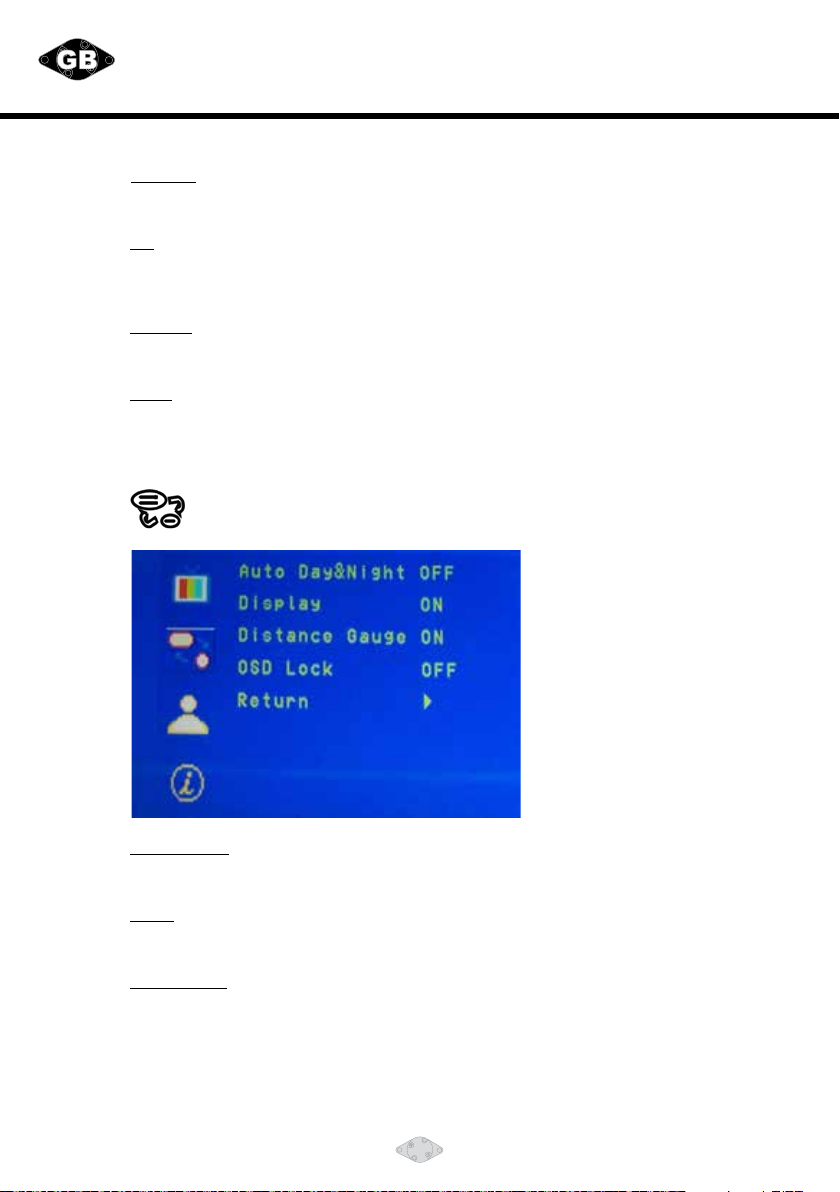
DISPLAY Menu
Thismenusetupcontainstheonscreenidentication
and the activation of the distance gauge.
Auto Day&Night
Select “ON” to activate the auto day & night function or “OFF” to
deactivate it. Default value is OFF.
Display
Select “ON” to show the source of video input title on screen or “OFF” to keep it invisible.
Default value is ON.
Distance Gauge
Set the distance gauge “ON” to show the distance gauge on screen while reserving
or “OFF” to deactivate. Default value is ON.
(This “DISTANCE GAUGE” is for user’s reference only)
8Vedpak 98_Version 6_12.2017
160775
OSD Lock
This function provides protection when an unauthorized person tries to access the OSD settings.
JUMP and Source key press simultaneously for over 5 seconds to unlock. Default value is OFF.
Users must turn on LCD in order to run unlock process. All function buttons are still
working during OSD Menu lock up period.
Return
Return to OSD menu selection screen.
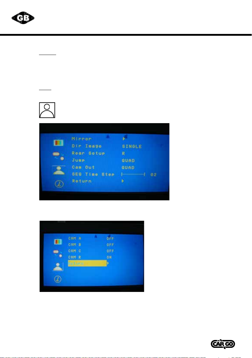
CAMERA Menu
This menu set up contains the on Camera and Jump setting.
MIRROR:
Select"ON"toactivatethemirrorfunctionfordierentcamerasor"OFF"foranormalimage.
Default values are following below setting.
CAM A ”OFF”
CAM B ”OFF”
CAM C ”OFF”
CAM R ”ON”

9
Vedpak 98_Version 6_12.2017
160775
Dir Image
The screen image setting of this panel during left / right turn:
TRIPLE: When you are making a right turn or left turn, the screen of
panel will display triple images for left hand side, right
hand side and rear view when you are making a right turn or left turn.
DUAL: With proper wiring, the screen will display dual image for
both rear and right hand side view when making a right turn.
While left turning, the screen will show dual image for both
rear and left hand side view.
SINGLE: Screen shows only single picture on direction turn. The screen
will show only left side view on left turn and only right side view on right turn.
Default value is SINGLE.
Rear Setup
The screen image setting of this panel during reverse gear:
R: Screen will display single image for Cam R only.
R+A: Screen will display dual image for both Cam R and Cam A.
R+B: Screen will display dual image for both Cam R and Cam B.
R/AB Screen will display triple image from Cam R ` Cam A ` Cam B.
R+AB Screen will display triple image from Cam R ` Cam A ` Cam B.
Default value is R.
Menu
CAM R
CAM B
CAM A
CAM R
CAM BCAM A

10 Vedpak 98_Version 6_12.2017
160775
Jump
By pressing this button, the driver will be able to obtain the image
selected under this setting.
QUAD Obtain image from all camera input in quad picture while
pressing the JUMP button and press again to return the default
screen.
SEQ. Corresponding with “SEQ. Timer Step” setting to jump channel
by time sequence.
CAM A Obtain image from camera A while pressing the JUMP button and
press again to return the default screen.
CAM B Obtain image from camera B while pressing the JUMP button and
press again to return the default screen.
CAM C Obtain image from camera C while pressing the JUMP button and
press again to return the default screen.
CAM R Obtain image from camera R while pressing the JUMP button and
press again to return the default screen.
CAM A+B Obtain image from camera A+B in dual picture while pressing the
JUMP button and press again to return the default screen.
CAM C+R Obtain image from camera C+R in dual picture while pressing the
JUMP button and press again to return the default screen.
CAM A+R Obtain image from camera A+R in dual picture while pressing the
JUMP button and press again to return the default screen.
CAM R+B Obtain image from camera R+B in dual picture while pressing the
JUMP button and press again to return the default screen.
CAM A+C Obtain image from camera A+C in dual picture while pressing the
JUMP button and press again to return the default screen.
CAM C+B Obtain image from camera C+B in dual picture while pressing the
JUMP button and press again to return the default screen.
CAM R/AB Obtain image from camera R+A+B in triple picture while pressing
the JUMP button and press again to return the default screen.
CAM R+AB Obtain image from camera R+A+B in triple picture while pressing
the JUMP button and press again to return the default screen.
Default value is QUAD.
Cam Out
Composite video loop out to recorder, monitor or other device.
QUAD Recording or viewing from the output device in quad mode
CAM A Recording or viewing from the output device for CAM A image
CAM B Recording or viewing from the output device for CAM B image
CAM C Recording or viewing from the output device for CAM C image
CAM R Recording or viewing from the output device for CAM R image
Default value is QUAD.
SEQ Time Step
Select Cam A/B/C/R switching time
setting value from 02~100
Default value is “02”
RETURN
Return to OSD menu selection screen.
Information
This menu set up contains Recall & Exit function.
Recall Recall factory default.
Exit Exit OSD menu.
Notice: Firmware version has shown on last column.
11
Vedpak 98_Version 6_12.2017
160775
Information
This menu set up contains Recall & Exit function.
Recall Recall factory default.
Exit Exit OSD menu.
Notice: Firmware version has shown on last column.
INSTALLATION FOR COLOUR CAMERA
INSTALLATION
With standard mounting bracket and fasteners included in
the package, the camera can be mounted rmly
at the required position of the vehicle.
1. Install the camera on the mounted camera bracket using
proper fasteners (included in the package).
Decide direction for the camera to view when installing
the camera on the bracket.
2. Run the built-in camera cable connection (1.5 mtr) to
monitor with camera extension cable
(20 mtr. standard length included in the package) into the
vehicle body (make a 13 mm. (½") hole on the vehicle
bodyifnecessary).Connectthecableconnectorsrmly
inside the vehicle with aid of a Loop-tie, and use weather
sealer strip to help protect the cable connection. Seal the
hole properly with weather sealant where the cable runs
through vehicle body
3. For maximum weather protection, the cable connection is
always recommended NOT to be left outside the vehicle.
4. This device has the function of night viewing. In the dark,
the IR will be enabled and the image is more clearly.
CONNECTION OF CAMERA 5
Connection of camera 5 is done using the adapter Cargo
160603.
Yellow RCA jack to VIDEO IN.
White RCA jack to AUDIO IN.
Furthermore 12 V / GND is connected to the camera via the
red and black leads of the adapter.
CAUTION
1. Adjust the camera angle so that the rear bumper or the
rear end of the vehicle is visible on the monitor (at the
bottom brim of the view).
2. To prevent vibration, be sure to install the camera in a
position at which it can be installed securely. Take the
necessary measures for reinforcement if there is no place
the camera can be installed
securely.
3. Note that there will be blind spots if the camera is
installed on the rear bumper, step, or in other low posi-
tion. Avoid installing the camera in places where the lens
can be easily get dirty from mud, exhaust gases, ect.
4. Be sure to waterproof the holes used to install the
camera mounting bracket on the car, the bolts, and the
cable holes.
12 13 Vedpak 98UK_Version 5_010909
160775
GB
INSTALLATION FOR COLOUR CAMERA
INSTALLATION
With standard mounting bracket and fasteners included in
the package, the camera can be mounted firmly
at the required position of the vehicle.
1. Install the camera on the mounted camera bracket using
proper fasteners (included in the package).
Decide direction for the camera to view when installing
the camera on the bracket.
2. Run the built-in camera cable connection (1.5 mtr) to
monitor with camera extension cable
(20 mtr. standard length included in the package) into the
vehicle body (make a 13 mm. (½") hole on the vehicle
body if necessary). Connect the cable connectors firmly
inside the vehicle with aid of a Loop-tie, and use weather
sealer strip to help protect the cable connection. Seal the
hole properly with weather sealant where the cable runs
through vehicle body
3. For maximum weather protection, the cable connection is
always recommended NOT to be left outside the vehicle.
4. This device has the function of night viewing. In the dark,
the IR will be enabled and the image is more clearly.
CONNECTION OF CAMERA 5
Connection of camera 5 is done using the adapter Cargo
160603.
Yellow RCA jack to VIDEO IN.
White RCA jack to AUDIO IN.
Furthermore 12 V / GND is connected to the camera via the
red and black leads of the adapter.
CAUTION
1. Adjust the camera angle so that the rear bumper or the
rear end of the vehicle is visible on the monitor (at the
bottom brim of the view).
2. To prevent vibration, be sure to install the camera in a
position at which it can be installed securely. Take the
necessary measures for reinforcement if there is no place
the camera can be installed
securely.
3. Note that there will be blind spots if the camera is
installed on the rear bumper, step, or in other low position.
Avoid installing the camera in places where the lens can
be easily get dirty from mud, exhaust gases, ect.
4. Be sure to waterproof the holes used to install the
camera mounting bracket on the car, the bolts, and the
cable holes.

12 Vedpak 98_Version 6_12.2017
160775
VEHICLE INSTALLATION:
1. Install camera R (for rear view).
2. Use a measuring tool to mark out the distance behind the vehicle.
3. Adjust the viewing angle of the camera so that the distance gauge shown from the TFT
match to the distance behind the vehicle.
Switch to Rear view with source button, the screen always display on 16:9
While rear viewing, the screen always display on 4:3 to correct size percentage
SOURCE button: Rear viewing:
9
4
3
16
14 Vedpak 98UK_Version 5_010909
160775
GB
15
VEHICLE INSTALLATION:
1. Install camera R (for rear view).
2. Use a measuring tool to mark out the distance behind the vehicle.
3. Adjust the viewing angle of the camera so that the distance gauge shown from the TFT
match to the distance behind the vehicle.
Switch to Rear view with source button, the screen always display on 16:9
While rear viewing, the screen always display on 4:3 to correct size percentage
SOURCE button: Rear viewing:
9
4
3
16

13
Vedpak 98_Version 6_12.2017
160775
MONITOR SPECIFICATIONS:
Screen size 7" (Diagonal) 16:9.
Active area 154.08 x 86.58 mm.
Pixelconguration 0.107x0.370.
Resolution 2400 x 480.
Viewing angle 60°.
Power source DC 9.6 V. ~ DC 32 V.
Contrast ratio 500:1.
Brightness 400 cd/cm².
Input Interface
Composite connector RCA.
Input signal 1 Vpp.
Impedance 75 W.
Camera
Connector 6 pin mini din.
Input video signal level 1 Vpp.
Impedance 75 W.
Input audio signal level 1 Vpp.
Power output DC 12 V. 350 mAmp.
AV Audio In
Connector RCA.
Input signal level 1Vpp.
Impedance 1 KW.
Output Interface
Composite Life video out.
Connector RCA.
Input signal level 1Vpp.
Composite Video Cam out.
Connector RCA.
Input signal level 1Vpp.
Impedance 75 W.
Audio Live Out
Connector RCA.
Input signal level 1Vpp.
Impedance 1 KW.
Audio
Weight Nt. 2 kg. Br. 2.28 kg.
Dimension L: 192 mm. H: 140,5 mm. D: 51,8 mm.
Environmental -10C°~70C°.
Storage temperatur -30C°~80C°.
Humidity 20%~80%.
Thebrightnessandcontrastratiospecicationsarefrompanelspecication.
DesignandSpecicationsaresubjecttochangewithoutnotice.
14 Vedpak 98_Version 6_12.2017
160775
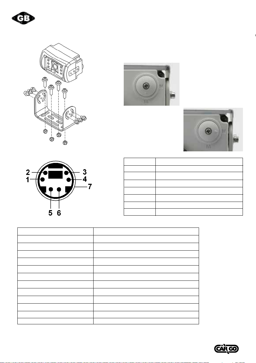
Camera Mirror (M) / Normal (N) adjustment
For mirror function -
Turn arrow to M.
For normal function -
Turn arrow to N.
Pin No.
1
2
3
4
5
6
7
Part description
Audio
Power
Video
GND
NIL
Mirror
NIL
Function of the Audio
Cam A Audio from Cam A
Cam B Audio from Cam B
Cam C Audio from Cam C
Cam R Audio from Cam R
Cam A + Cam B Audio from Cam A
Cam C+ Cam R Audio from Cam R
Cam A+ Cam R Audio from Cam R
Cam R+ Cam B Audio from Cam R
Cam A + Cam C Audio from Cam A
Cam C+ Cam B Audio from Cam C
Cam R / Cam AB Audio from Cam R
Quad Audio from Cam R
AV Audio from AV
Cam Out: Composite video loop out signal to recorder, monitor or other device.
Live Video/Audio Out: On screen video/audio signal loop out to recorder, monitor or other device.
16 Vedpak 98UK_Version 5_010909
160775
GB
17
Camera Mirror (M) / Normal (N) adjustment
For mirror function -
Turn arrow to M.
For normal function -
Turn arrow to N.
Camera Harness:
Pin No.
1
2
3
4
5
6
7
Part description
Audio
Power
Video
GND
NIL
Mirror
NIL
Function of the Audio
Cam A Audio from Cam A
Cam B Audio from Cam B
Cam C Audio from Cam C
Cam R Audio from Cam R
Cam A + Cam B Audio from Cam A
Cam C+ Cam R Audio from Cam R
Cam A+ Cam R Audio from Cam R
Cam R+ Cam B Audio from Cam R
Cam A + Cam C Audio from Cam A
Cam C+ Cam B Audio from Cam C
Cam R / Cam AB Audio from Cam R
Quad Audio from Cam R
AV Audio from AV
Cam Out: Composite video loop out signal to recorder, monitor or other device.
Live Video/Audio Out: On screen video/audio signal loop out to recorder, monitor or other device.
Camera Harness:

15
Vedpak 98_Version 6_12.2017
160775
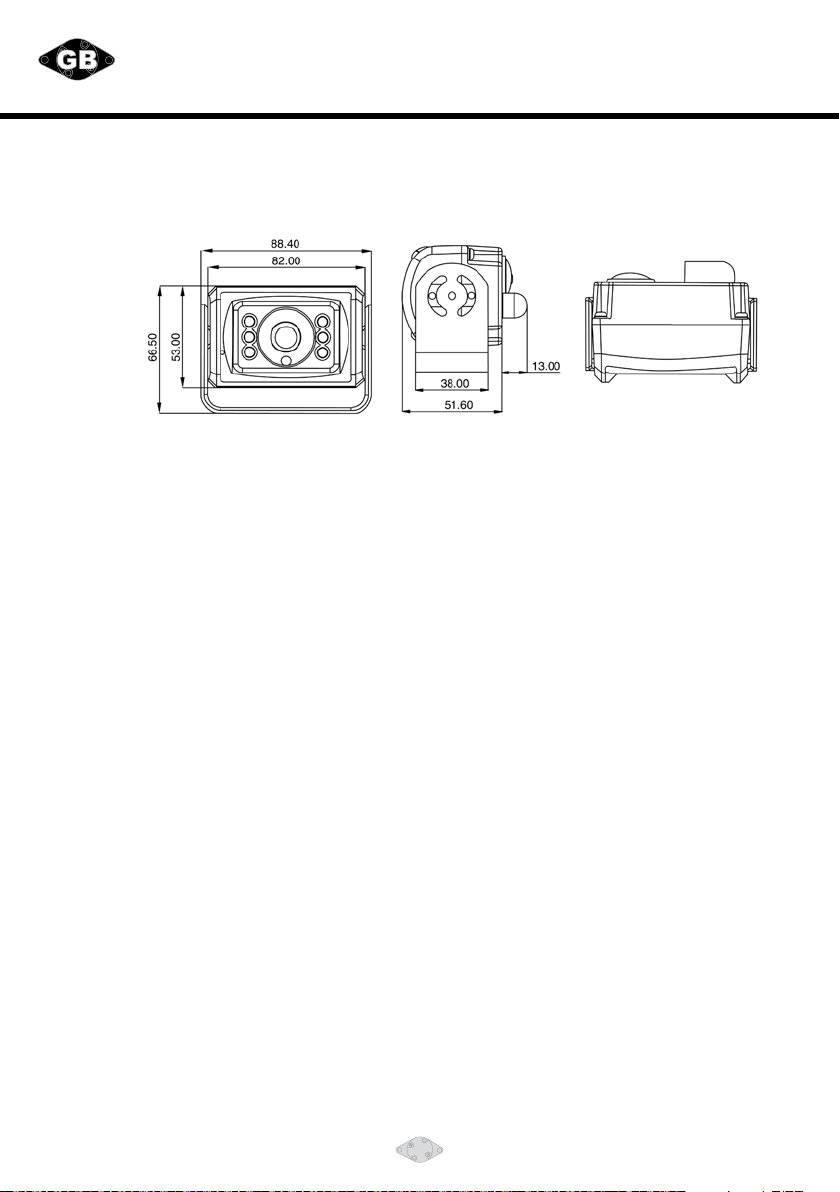
CAMERA SPECIFICATIONS
Pick-up Device................................................1/3" interline transfer CCD
Total Pixels....................................................NTSC:537(H) x 505(V)
PAL:537(H) x 597(V)
EectivePixels ...............................................NTSC:510(H) x 492(V)
PAL:500(H) x 582(V)
Resolution .....................................................W/ 420 TV lines
Sync, System..................................................Internal
Scanning System .............................................2:1 Interlace
S/N Ratio ......................................................More than 45dB (AGC OFF)
Electronic Shutter ...........................................Auto Electronic Shutter 1/60 (1/50) ˜1/100,000 sec.
Min. Illumination .............................................0 Lux (F2.0) w/ IR LED ON
Video Output .................................................Composite 1.0 Vp-p / 75 ohm
Automatic Gain Control.....................................ON
Aperture Correction .........................................Ye s
Frequency Horizontal......................................NTSC: 15.734 KHz ; PAL: 15.625 Khz
Frequency Vertical .........................................NTSC: 59.94Hz ; PAL: 50Hz
IR Operation range...........................................<9±3.2 Lux ON ; >9±3.75 Lux OFF
LED Angle......................................................4 PCS 70° / 2 PCS 50° total 6 PCS LED
Lens Mount Type .............................................2.27 mm. F2.2
View Angle ....................................................H:122° V:91°
DC Power Source .............................................DC9.6 ˜12 V.
Power Consumption..........................................2.3 W (Max IR ON)
Current ........................................................190 mA (Max IR ON)
Audio Out .....................................................700 mV (10k OHM)
Dimension .....................................................88.4(W) x 66.5(H) x 51.6(D) mm.
Operation Temperature .....................................-20 to 70°C (-4 to 158°F)
Storage Temperature ........................................-30 to 80°C (-22 to 176°F)
16 Vedpak 98_Version 6_12.2017
160775
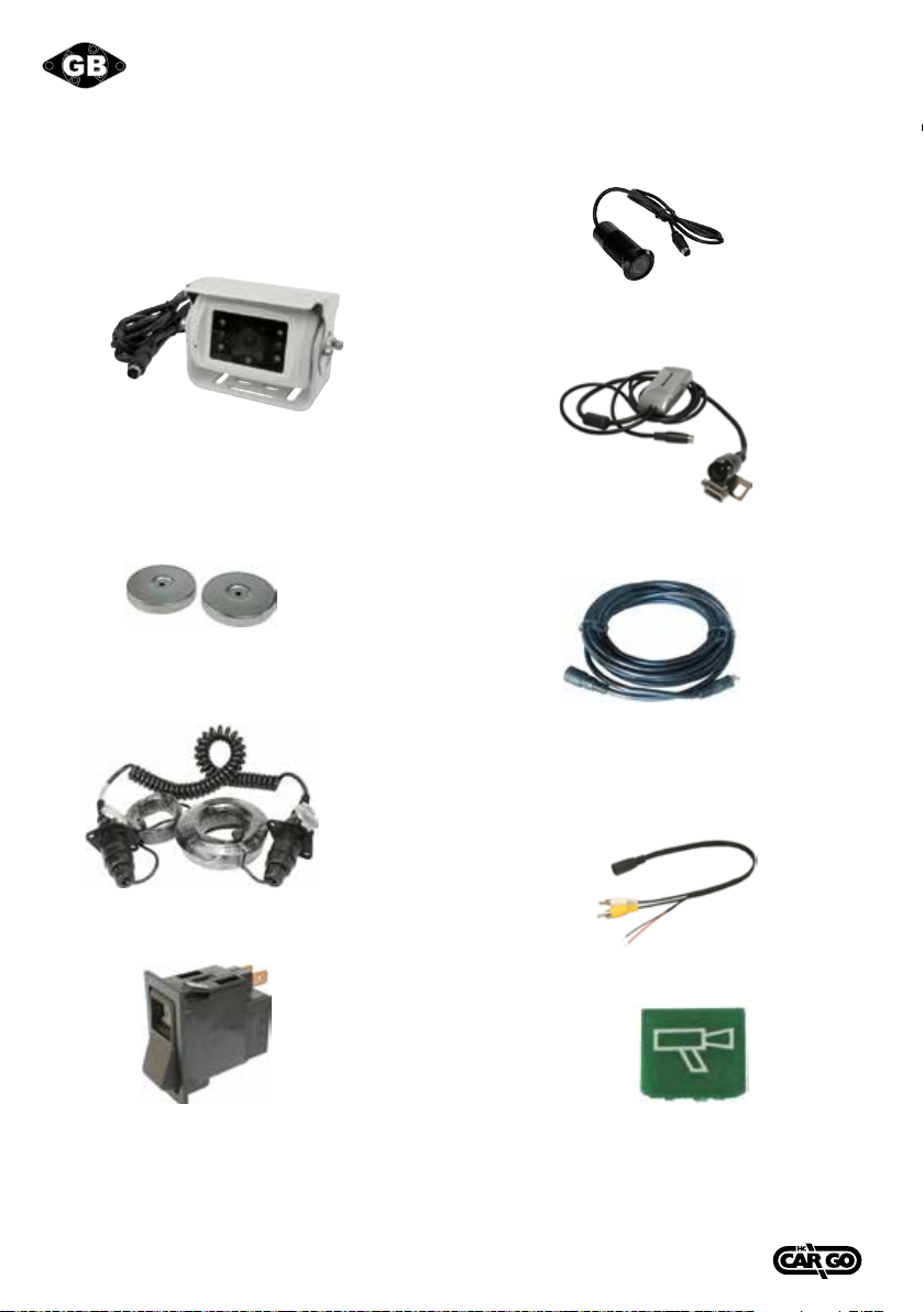
ACCESSORIES:
160796
Camera w/ infrared LED’s for night vision.
Wide view angle, 112° horizontal, 91° vertical,
156° diagonal.
170942
Magnet w/ metalbase for cameras.
160663
Trailer cable Kit.
W/ 3.5 mtr. coiled cable.
Switch w/ location and function light.
ON/OFF.
180206 12 V.
180207 24 V.
160610
Camera, O.D. 30 mm. L. 70 mm.
Wide view angle, 130° diagonal.
160790
Camera, O.D. 21 mm. L. 40 mm.
Wide view angle, 170° diagonal.
Extension cables.
160672 6 mtr.
160613 10 mtr.
160612 15 mtr.
160611 20 mtr.
160603
Connection cable from 6 PIN MINI DIN to RCA.
Symbolplates for HC-CARGO 180206 and 180207.
181462 Green.
181463 Red.
181464 Camera.
INHALT:
Besonderheiten ................................................... 18
Einbau des Monitors.............................................. 18
Signalkabelbeschreibung ........................................ 18
Kontrollkabelbeschreibung ..................................... 19
Schalter und Bedienung ......................................... 20
OSD-Menü - Anzeige .............................................. 21
Anzeige ............................................................. 21
Spiegelfunktion.................................................... 23
Kamera.............................................................. 23
Werkseinstellungen .............................................. 26
Kamera - Ausgang ................................................. 24
OSD - Anzeige verlassen ......................................... 24
Installation der Kamera.......................................... 26
Einstellung der Entfernungsanzeige .......................... 27
Monitoreigenschaften............................................ 28
Kameraeigenschaften ............................................ 30
Zubehör............................................................. 31
PACKUNGSINHALT:
1. 7" LED Monitor 16:9.
2. Sonnenblende.
3. Einbauhalterungen.
4. Einbauzubehör.
5. Steuerungskabel.
6. Kamera mit Infrarot LED´s mit eingebautem Mikrofon.
7. 20 mtr. Kamerakabel.
8. Bedienungsanweisung.
ACHTUNG:
Fügen Sie keine Teile hinzu oder verwenden Sie irgendwelches Zubehör, das vom
Hersteller nicht im Lieferangebot steht.
Fahren Sie nie weiter, als es Ihnen die Systemanzeige vorgibt, um Verkehrsunfälle
zu vermeiden. Üben Sie nie Druck auf den Bildschirm aus.
Sprühen Sie nie irgendwelche üssigen Reinigungsmittel auf den Bildschirm.
Benutzen Sie zur Reinigung nur ein LCD-Reinigungstuch.

17
Vedpak 98_Version 6_12.2017
160775
INHALT:
Besonderheiten ................................................... 18
Einbau des Monitors.............................................. 18
Signalkabelbeschreibung ........................................ 18
Kontrollkabelbeschreibung ..................................... 19
Schalter und Bedienung ......................................... 20
OSD-Menü - Anzeige .............................................. 21
Anzeige ............................................................. 21
Spiegelfunktion.................................................... 23
Kamera.............................................................. 23
Werkseinstellungen .............................................. 26
Kamera - Ausgang ................................................. 24
OSD - Anzeige verlassen ......................................... 24
Installation der Kamera.......................................... 26
Einstellung der Entfernungsanzeige .......................... 27
Monitoreigenschaften............................................ 28
Kameraeigenschaften ............................................ 30
Zubehör............................................................. 31
PACKUNGSINHALT:
1. 7" LED Monitor 16:9.
2. Sonnenblende.
3. Einbauhalterungen.
4. Einbauzubehör.
5. Steuerungskabel.
6. Kamera mit Infrarot LED´s mit eingebautem Mikrofon.
7. 20 mtr. Kamerakabel.
8. Bedienungsanweisung.
ACHTUNG:
Fügen Sie keine Teile hinzu oder verwenden Sie irgendwelches Zubehör, das vom
Hersteller nicht im Lieferangebot steht.
Fahren Sie nie weiter, als es Ihnen die Systemanzeige vorgibt, um Verkehrsunfälle
zu vermeiden. Üben Sie nie Druck auf den Bildschirm aus.
Sprühen Sie nie irgendwelche üssigen Reinigungsmittel auf den Bildschirm.
Benutzen Sie zur Reinigung nur ein LCD-Reinigungstuch.

18 Vedpak 98_Version 6_12.2017
160775
1. Cam-R.(Mini DIN) Für Rückfahrsichtkamera.
(Auswahl der CAM-R setzt alle anderen
Einstellungen von Kameras außer Kraft).
2. Cam-A.
Für den ersten Kamera-Anschluss.
3. Cam-B.
Für den zweiten Kamera-Anschluss.
4. Cam-C.
Für den dritten Kamera-Anschluss.
5. Direkter Video-Ausgang. (RCA-Weißes Kabel).
Bildschirmausgang (Für Aufnahmen über VCR, zweiten Bildschirm oder andere Geräte).
6. Direkter Audio-Ausgang. (RCA-Schwarzes Kabel).
Audioausgang (Für Aufnahmen über VCR, zweiten Bildschirm oder andere Geräte).
7. AV VIDEO IN (RCA-Gelbes Kabel).
Anschluss für jedes Video-Signal wie DVD, VCD, Spielekonsole, Digitaler Fotoapparat oder Kamera.
8. AV AUDIO IN (RCA-Rotes Kabel).
Anschluss für jedes Audio-Signal wie DVD, VCD oder Spielekonsole.
9. CAM OUT (RCA-Grünes Kabel). Video-Schleife (Für Aufnahmen, zweiten Monitor oder andere
Geräte). Einstellung über OSD unter CAMERA im Bildschirmfenster.
BESONDERHEITEN:
Erweitertes OSD-Menü für einfache Bedienung
Unterstützt bis zu 4 CCD Kameraeingänge (6 pin Mini DIN).
Extra RCA-Eingang für Multimedia (VCD, DVD, Spielekonsole).
2 Video / 1 Audio Signalausgang möglich.
Unterstützt Einzel-/Doppel-/Dreifach- /Vierfach-Bildschirm (Kameraausgang)
Signalauslösung für hinten / Links / Rechts / AV.
Zweifache Bildschirmanzeige.
Menü-Kontrolle für individuelle normal/Spiegelanzeige.
Automatische Tag/Nacht Kontrolle mit CDS.
Automatische Erkennung für NTSC / PAL-System.
Unterstützt 9,6V ~ 32V Stromsystem
Professionelles stoßfestes Metallgehäuse
INSTALLATION DES MONITORS:
1. Überprüfen Sie den Packungsinhalt und stellen Sie sicher, dass alle Teile enthalten sind.
2. Klipsen Sie die Sonnenblende auf den Monitor und stellen Sie sicher, das sie
ordnungsgemäß befestigt ist.
3. Installieren Sie den Monitor auf die Halterung.
4. Richten Sie den Monitor vor dem Festziehen der Schrauben in einen passenden und bequemen
Betrachtungswinkel aus.
5. Schließen Sie das beigelegte Anschlusskabel an der Rückseite des Monitors an.
6. Die Monitorinstallation ist jetzt abgeschlossen. Die Steuerleitungen sind mit einem
Aufkleber markiert, um die Signalfunktionen anzuzeigen.
SIGNAL/STEUERLEITUNGSBELEGUNG:
4Vedpak 98D_Version 5_010909
160775
D
5
1. Cam-R.(Mini DIN) Für Rückfahrsichtkamera.
(Auswahl der CAM-R setzt alle anderen
Einstellungen von Kameras außer Kraft).
2. Cam-A.
Für den ersten Kamera-Anschluss.
3. Cam-B.
Für den zweiten Kamera-Anschluss.
4. Cam-C.
Für den dritten Kamera-Anschluss.
5. Direkter Video-Ausgang. (RCA-Weißes Kabel).
Bildschirmausgang (Für Aufnahmen über VCR, zweiten Bildschirm oder andere Geräte).
6. Direkter Audio-Ausgang. (RCA-Schwarzes Kabel).
Audioausgang (Für Aufnahmen über VCR, zweiten Bildschirm oder andere Geräte).
7. AV VIDEO IN (RCA-Gelbes Kabel).
Anschluss für jedes Video-Signal wie DVD, VCD, Spielekonsole, Digitaler Fotoapparat oder Kamera.
8. AV AUDIO IN (RCA-Rotes Kabel).
Anschluss für jedes Audio-Signal wie DVD, VCD oder Spielekonsole.
9. CAM OUT (RCA-Grünes Kabel). Video-Schleife (Für Aufnahmen, zweiten Monitor oder andere
Geräte). Einstellung über OSD unter CAMERA im Bildschirmfenster.
besonderheiten:
Erweitertes OSD-Menü für einfache Bedienung
Unterstützt bis zu 4 CCD Kameraeingänge (6 pin Mini DIN).
Extra RCA-Eingang für Multimedia (VCD, DVD, Spielekonsole).
2 Video / 1 Audio Signalausgang möglich.
Unterstützt Einzel-/Doppel-/Dreifach- /Vierfach-Bildschirm (Kameraausgang)
Signalauslösung für hinten / Links / Rechts / AV.
Zweifache Bildschirmanzeige.
Menü-Kontrolle für individuelle normal/Spiegelanzeige.
Automatische Tag/Nacht Kontrolle mit CDS.
Automatische Erkennung für NTSC / PAL-System.
Unterstützt 9,6V ~ 32V Stromsystem
Professionelles stoßfestes Metallgehäuse
installation des Monitors:
1. Überprüfen Sie den Packungsinhalt und stellen Sie sicher, dass alle Teile enthalten sind.
2. Klipsen Sie die Sonnenblende auf den Monitor und stellen Sie sicher, das sie
ordnungsgemäß befestigt ist.
3. Installieren Sie den Monitor auf die Halterung.
4. Richten Sie den Monitor vor dem Festziehen der Schrauben in einen passenden und bequemen
Betrachtungswinkel aus.
5. Schließen Sie das beigelegte Anschlusskabel an der Rückseite des Monitors an.
6. Die Monitorinstallation ist jetzt abgeschlossen. Die Steuerleitungen sind mit einem
Aufkleber markiert, um die Signalfunktionen anzuzeigen.
signal/steuerleitungsbelegung:

19
Vedpak 98_Version 6_12.2017
160775
ANSCHLUSSKABELBELEGUNG:
Kabelkonguration
Schließen Sie das rote Kabel
(Spannungsversorgung) der
Kontrolleinheit nicht direkt
an die Fahrzeugbatterie
an. Schließen Sie das rote
Kabel an die Radiostellung
des Zündstartschalters an.
Nichtbeachtung kann einen
dauerhaften Schaden des
Produktes hervorrufen.
KABELFARBE
Rot
Schwarz
Weiss
Blau
Orange
Gelb
FUNKTION
Batterie
(DC 9.6-DC32V.)
Masse
Parkkontrolle
Rückfahrkontrolle
Kamera 2
Kamera 1
BEMERKUNG
Aktive Masse
Aktiver Anschluss.
Anschluss an
Rückfahrscheinwerfer
Aktiver Anschluss.
Anschluss für Ansteuerung
Kamera rechts.
Aktiver Anschluss.
Anschluss für
Ansteuerung Kamera links.
BILDSCHIRMANSICHT
1. Aktivierung der Schaltkabel für rückwärts, rechts oder links übergeht eine Bildauswahl und zeigt die
eingeschaltete Kamera.
2. *Wenn die Handbremse gezogen ist, muss der Benutzer wieder den Knopf SOURCE drücken,
um das AV IN Bild anzuzeigen.
4
5Vedpak 98D_Version 5_010909
160775
D
anschlusskabelbelegung:
Kabelkonfiguration
Schließen Sie das rote Kabel
(Spannungsversorgung) der
Kontrolleinheit nicht direkt
an die Fahrzeugbatterie
an. Schließen Sie das rote
Kabel an die Radiostellung
des Zündstartschalters an.
Nichtbeachtung kann einen
dauerhaften Schaden des
Produktes hervorrufen.
kabelFarbe
Rot
Schwarz
Weiss
Blau
Orange
Gelb
Funktion
Batterie
(DC 9.6-DC32V.)
Masse
Parkkontrolle
Rückfahrkontrolle
Kamera 2
Kamera 1
beMerkung
Aktive Masse
Aktiver Anschluss.
Anschluss an
Rückfahrscheinwerfer
Aktiver Anschluss.
Anschluss für Ansteuerung
Kamera rechts.
Aktiver Anschluss.
Anschluss für
Ansteuerung Kamera links.
bildschirMansicht
Jump So urc e Po wer
M e nu
AV
Jump S ourc e Power
M e nu
CAM R
CAM R CAM B
CAM A C AM R
1. Aktivierung der Schaltkabel für rückwärts, rechts oder links übergeht eine Bildauswahl und zeigt die
eingeschaltete Kamera.
2. *Wenn die Handbremse gezogen ist, muss der Benutzer wieder den Knopf SOURCE drücken,
um das AV IN Bild anzuzeigen.
Jump Sourc e rewoP
M en u
AV
Jum p Source Power
M enu
CAM R
CAM R CAM B
CAM A CA M R

20 Vedpak 98_Version 6_12.2017
160775
BILDSCHIRMBEDIENUNG:
POWER: POWER Schalter zum aktivieren des Monitors oder in den Stand-By Modus zu schalten.
SOURCE: Source Schalter zum Auswählen der Bildsequenz CAM A+B gCAM C+R g
CAM ACAM BCAM CCAM R CAM A+B CAM C+R
CAM A+RCAM R+BCAM A+CCAM C+B CAM R/AB CAM R+ABCAM A……
Bei angezogener Handbremse diesen Knopf drücken, um die Bildsequenz zu wählen.
AVCAM A+BCAM C+RCAM A+RCAM R+BCAM A+C
CAM C+BCAM R/ABCAM R+ABCAM ACAM BCAM CCAM R AV……..
JUMP: Diesen Knopf drücken, um Bild der gewünschten Kamera zu zeigen. Der Benutzer kann
QUADSEQCAM A+BCAM C+RCAM A+RCAM R+B
CAM A+CCAM C+BCAM R/AB CAM R+AB CAM A CAM B
CAM CCAM R standardgemäß über OSD auswählen.
MENU: Der MENU Schalter unterstützt folgende Funktionen:
1. Aktivieren des OSD-Menüs:
Drücken Sie den Menu-drehschalter zum aktivieren des OSD-Menüs. Nachdem das OSD-Menü
aktiviert ist, wird im Falle, dass der Benutzer im Menü nicht weitergeht, das OSD-Menü
innerhalb von 20 Sekunden automatisch abgeschaltet.
2. Eingabefunktion: Benutzen Sie die Menü-Taste als "Enter" Taste zur
Funktionauslösung im OSD-Menü.
3. Lautstärkeregelung: Verlassen Sie das OSD-Menü. Um die Lautstärke einzustellen,
drehen Sie links oder rechts am Menü-Drehschalter.
Table of contents
Languages:
Other hc-cargo Automobile Accessories manuals


Popular Automobile Accessories manuals by other brands


Toyota
Toyota 4RunneR 2014 Accessories guide

NAE National
NAE National WiBar WB-720 Instruction manual & user guide

Axxess
Axxess AXDSPL-GL10 installation instructions

Whispbar
Whispbar K470W Fitting Instructions for Basic Carrier

Car-Interface
Car-Interface CI-RL3-MIB-TT manual

BURY
BURY UNIVERSAL XXL Quick user guide


