manuals.online logo
Brands
  1. Home
  2. •
  3. Brands
  4. •
  5. Delta
  6. •
  7. Inverter
  8. •
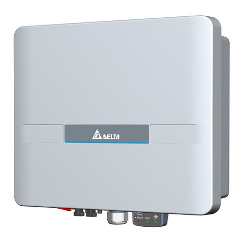
  9. Delta H5A 222 Series User manual

Delta H5A 222 Series User manual

Quick Installation Guide
Grid-tie Transformerless Solar Inverter
Model name: H5A_222
Caution
Descriptions of Parts and Components
Dimensions and Function Introduction
①②
③⑥ ⑤
④
Object
PV Inverter
Quick Installation Guide
AC Plug
Wall-Mount
Bracket
Digital input connector
Dry contact connector
Qty
1
1
1
1
2
Description
Solar inverter
Important safety instructions and technical specifications
should be followed during installation.
Connector for AC connection
DC Plug
①
②
③
⑤
⑥
④2 pairs H4 connector for DC connection
To mount the solar inverter securely on the wall.
Digital input connector and dry contact connector for
function port.
If there is any visible damage to the inverter/accesories or any damage to the
packaging, please contact your inverter supplier before installation.
380 130
91
318
346.8
Grounding
AC connector
Label
DC connectors Comm. Interface
Function port
DC
switch
LED and Button
The LEDs indicate the operating state of the inverter.
The reset button function
Status Explanation
Steady on The red LED glowing indicates error or fault.
( see user manual - chapter 9.1 Error Message )
Steady on The inverter is connected to the grid.
Flashing The red LED flashing indicates error "E34:Insulation"
Flashing The inverter is on countdown status, before connecting grid.
Steady on The Wi-Fi module is on data transmission.
LED
Earth Fault
Alarm
Grid
Wi-Fi
Wi-Fi LED Status Explanation
Wi-Fi LED flashing once every
one seconds
Reset Wi-Fi module, and Wi-Fi password
returns to the default: DELTASOL
Wi-Fi LED flashing once every
half a second Reset Wi-Fi module
Operation
Push 3s~10s
Push 20s~
No flash No functionPush 10s~20s
Mounting
227
60 7.5
22.5
37.5
46
250
291
Φ6.0*6
①
②
③
More H5A_222 details please scan QR-code to user manual.
More DC1_100 details please scan QR-code to user manual.
Setting of APP please scan QR-code to APP guideline.
https://mydeltasolar.deltaww.com/index.php?p=manual
http://www.deltaww.com/Products/CategoryListT1.aspx?CID=05
010101&PID=4866&hl=en-US&Name=H5A_222
https://mydeltasolar.deltaww.com/?p=product_manual
During operation of electrical devices, certain parts are under dangerous voltage.
Inappropriate handling can lead to physical injury and material damage.
Always adhere to the installation regulations.
Installation may only be conducted by certified electricians.
Warning
Do not install the unit near or on flammable surfaces.
Mount the unit tightly on a solid/smooth surface.
When the photovoltaic array is exposed to light, it supplies a DC voltage to the Inverter,
a shock hazard may exist due to output wires or exposed terminals.
To reduce the risk of shock during installation, cover the array with an opaque (dark)
material
and ensure that the Disconnect Device in the inverter is set to OFF before
commencing any wiring.
Before commencing AC wiring, please ensure all AC circuit breakers are switched off.
Caution
The maximum open circuit voltage of the PV Array must not exceed 600Vdc.
unit: mm
unit: mm
5013276600
20191002
■ DRM (Digital input)
Function Port Specifications
1. Click [On] to turn on the function.  2. Click [SET]
3. Follow below table to set the specific power limit value, you can check the percentage
by DRM(%) on the APP.
■ PARTIAL/ZERO EXPORT
The function has to be used with current sensor (optional part).
1. Click [On] to turn on the internal meter function.
2. Click [On] to turn on the partial/zero export function.
3. Set the Rate% base on power company or local regulation.
4. Set the Sign capacity & PV capacity, the inverter will use the lower value as the power
limit reference, and then click [SET].
■ DRY CONTACT
1. The types of alert are “On grid, Insulation, Alarm, Error and Fault”, select to trigger.
2. Click [SET]
3. When the Inverter triggers the selected alarm, the inverter will close dry contact relay
to trigger external device.
Digital input Internal meter
Dry contact
* Screw torque required for
assembling: 8±2 kgf-cm
Short pins Inverter behavior (AU)
D6 & D2
D6 & D1
D6 & D3
D6 & D4
D6 & D5
DRM 7 - Power de-rating to 75%
DRM 5 - Power de-rating to 0%
DRM 6 - Power de-rating to 50%
DRM 8 - Power de-rating to 100%
DRM 0 - Disconnect from grid
D1
D2
D3
D4
D5
D6
Dry
contact
Dry
contact
Internal
meter
Internal
meter
■ DRM (Digital input) ■ PARTIAL/ZERO EXPORT ■ DRY CONTACT
Enclosure
Operating temperature
Relative humidity
Galvanic isolation
Safety class
Overvoltage category
Flicker impedance
Three-phase combinations
Max. input voltage
Operating voltage range
MPP range (rated power)
Normal voltage
MPP tracker
Startup voltage
Input connection
Max. inverter backfeed
current to the array
Maximum input current
Max. short circuit current (per MPPT)
Operating Altitude
Environmental category
Pollution degree
Nominal output power 1
Maximum power
Nominal output current
Maximum output fault current
Maximum output over current protection
Frequency
Total harmonic distortion
2
Power factor 2
Peak efficiency
EU efficiency
Output connection
Voltage
Max. output current
Current (inrush)
(A, peak and duration)
Housing
Cooling
IP rating
External communication
Weight
Dimensions
GENERAL
DC INPUT (Solar side)
AC OUTPUT (Grid side)
MECHANISM
REGULATIONS & DIRECTIVES
Safety
Grid interface
3
Harmonics
Immunity
Immunity
Emission
Variations and flicker
ESD
EFT
Surge
CS
PFMF
RS
Powder-coated aluminium
-25~60°C, full power up to 40°C
2000 m
0% – 95% non-condensing.
Outdoor, wet locations
No (TL Topology)
Class I metal enclosure with protective earth
Internal: II, External: III
AC output: III, DC input: II
Z = 0.4 + j 0.25 Ω (total impedance)
No
600 Vdc
350 Vdc
30-550 Vdc
240-500 Vdc
11 Adc for each /
22 Adc for total
2
13.9 A
0 A
35 Vdc
H4, 2 pairs
230Vac -20%~+22%
30 A peak, 1 ms
50/60 Hz
<3% @Rated power
>0.99 @Rated power
97.5%
96.8%
IP 67 single-phase
5000 VA
5000 VA
25 A
25 A
22 A
23 A
Die casting
Convection cooling
IP65
Wi-Fi
12 kg
380 × 318 × 130 mm
IEC 61000-6-4, IEC 61000-6-3
EN 61000-6-2
IEC 61000-4-2
IEC 61000-4-3
IEC 61000-4-4
IEC 61000-4-5
IEC 61000-4-6
IEC 61000-4-8
IEC 62109-1 / -2, CE compliance
EN 61000-3-12
EN 61000-3-11
AS4777
1: (a) 4.99kVA max. for Australia (AU / NZ)
(b) 4.6kVA max. for Germany (DE)
2: reactive power control disabled
3: not support AS4777.2:2015 Single-phase inverters used in three-phase combinations
On
DRM(%): 100 %
DRM Status: Off
OTHER
PARTIAL
EXPORT DRY CONTACT
/ ZERO
DRM
SET
Off
SET
0 W
0 W
Info
Rate:
PARTIAL
EXPORT DRY CONTACT
/ ZERO
DRM
Info
0
0
0
%
Sign Capacity:
PVCapacity:
(kW)
(kW)
Meter total power :
Inverter total power:
OTHER
Off
On
Mode:
Internal meter:
Off
On
SET
Disable
Status:
PARTIAL
EXPORT DRY CONTACT
/ ZERO
DRM
OTHER
Login
8-16 characters (Aa-Zz;0-9)
Password:
Email:
Forget password Create account Language
Please select your device to continue:
Inve rter Data Co llector
your email
SIGN IN
Home
INVERTER STATUS:
ENERGY TOTAL:
STANDBY
0Wh
ENERGY TODAY
0 Wh
Purchased:
Feed-in:
0.0 kW
--- kW
0.0 kW
0.0 kW
Consumption:
Production:
10
5
0
Production[W]
54 6 7 8 9 10
11 12 13 1 4 15 16 17 18 1 9 20
Hour
Daily Mon th Year 20Y
HOME
INFO
HISTORY
SETTING
Initial Setting
Grid Setting
Network
Update
Other
1. Follow the APP guideline to create an account and connect to the inverter.
Starting up the inverter function
5. Enter password (please contact us)2. Click 3. Click “SETTING” 4. Click “Other”
2
1
1
11
3
4
2
4
2
2
❸
❹

Other manuals for H5A 222 Series

1

Other Delta Inverter manuals

Delta M30A 230 Specification sheet

Delta

Delta M30A 230 Specification sheet

Delta RPI M80U Specification sheet

Delta

Delta RPI M80U Specification sheet

Delta M100-212 Specification sheet

Delta

Delta M100-212 Specification sheet

Delta PPM CT16 101 Instruction sheet

Delta

Delta PPM CT16 101 Instruction sheet

Delta AU Series Specification sheet

Delta

Delta AU Series Specification sheet

Delta SOL10.0-1TR3-E4 Specification sheet

Delta

Delta SOL10.0-1TR3-E4 Specification sheet

Delta M6A User manual

Delta

Delta M6A User manual

Delta RPI Series Specification sheet

Delta

Delta RPI Series Specification sheet

Delta SOLIVIA 5.0 AP G3 Specification sheet

Delta

Delta SOLIVIA 5.0 AP G3 Specification sheet

Delta RPI E5 Specification sheet

Delta

Delta RPI E5 Specification sheet

Delta SOLIVIA 5.0 Specification sheet

Delta

Delta SOLIVIA 5.0 Specification sheet

Delta SOLIVIA 10 EU T4 TL Specification sheet

Delta

Delta SOLIVIA 10 EU T4 TL Specification sheet

Delta M50A_12s User manual

Delta

Delta M50A_12s User manual

Delta M Series Specification sheet

Delta

Delta M Series Specification sheet

Delta SOLIVIA 2.5 AP G3 TR Specification sheet

Delta

Delta SOLIVIA 2.5 AP G3 TR Specification sheet

Delta M250HV Installation and operation manual

Delta

Delta M250HV Installation and operation manual

Delta Solivia 2.5 Specification sheet

Delta

Delta Solivia 2.5 Specification sheet

Delta SOLIVIA 2.5 EU G3 Instruction Manual

Delta

Delta SOLIVIA 2.5 EU G3 Instruction Manual

Delta Solivia 2.5 Specification sheet

Delta

Delta Solivia 2.5 Specification sheet

Delta H25 Specification sheet

Delta

Delta H25 Specification sheet

Delta RPI153FA0E0000 User manual

Delta

Delta RPI153FA0E0000 User manual

Delta BDI Series Specification sheet

Delta

Delta BDI Series Specification sheet

Delta M42U Specification sheet

Delta

Delta M42U Specification sheet

Delta H5A 222 Series User manual

Delta

Delta H5A 222 Series User manual

Popular Inverter manuals by other brands

CPS SC14KTL-DO/US-208 Installation and operation manual

CPS

CPS SC14KTL-DO/US-208 Installation and operation manual

Sungrow SG30CX-NI user manual

Sungrow

Sungrow SG30CX-NI user manual

Sungrow SG36KTL-M user manual

Sungrow

Sungrow SG36KTL-M user manual

GENERGY LIMITED Series Instructions for use

GENERGY

GENERGY LIMITED Series Instructions for use

ABB UNO-DM-6.0-TL-PLUS Quick installation guide

ABB

ABB UNO-DM-6.0-TL-PLUS Quick installation guide

Conext XW+ 6848 NA owner's guide

Conext

Conext XW+ 6848 NA owner's guide

Growatt MOD 3000TL3-XH Installation & operation manual

Growatt

Growatt MOD 3000TL3-XH Installation & operation manual

ICMA S001 Technical data sheet

ICMA

ICMA S001 Technical data sheet

Omron JX -  1 System configuration

Omron

Omron JX - 1 System configuration

EBARA E-SPD Series Instruction and maintenance manual

EBARA

EBARA E-SPD Series Instruction and maintenance manual

RCA WR-99A Operating and maintenance instructions

RCA

RCA WR-99A Operating and maintenance instructions

K2 Systems S-DOME SYSTEM Assembly instructions

K2 Systems

K2 Systems S-DOME SYSTEM Assembly instructions

Bodine ELI Series Installation and operation instruction

Bodine

Bodine ELI Series Installation and operation instruction

AIMS PWRINV150W owner's manual

AIMS

AIMS PWRINV150W owner's manual

ESAB KHM 351 YS instruction manual

ESAB

ESAB KHM 351 YS instruction manual

SMA 9000TL manual

SMA

SMA 9000TL manual

Assurance Engineering Assuramce Emergency Lighting Si-125 Installation & operation manual

Assurance Engineering

Assurance Engineering Assuramce Emergency Lighting Si-125 Installation & operation manual

Schmalz ROB-SET ECBPMi MATCH UR quick start guide

Schmalz

Schmalz ROB-SET ECBPMi MATCH UR quick start guide

manuals.online logo
manuals.online logoBrands
  • About & Mission
  • Contact us
  • Privacy Policy
  • Terms and Conditions

Copyright 2025 Manuals.Online. All Rights Reserved.