4
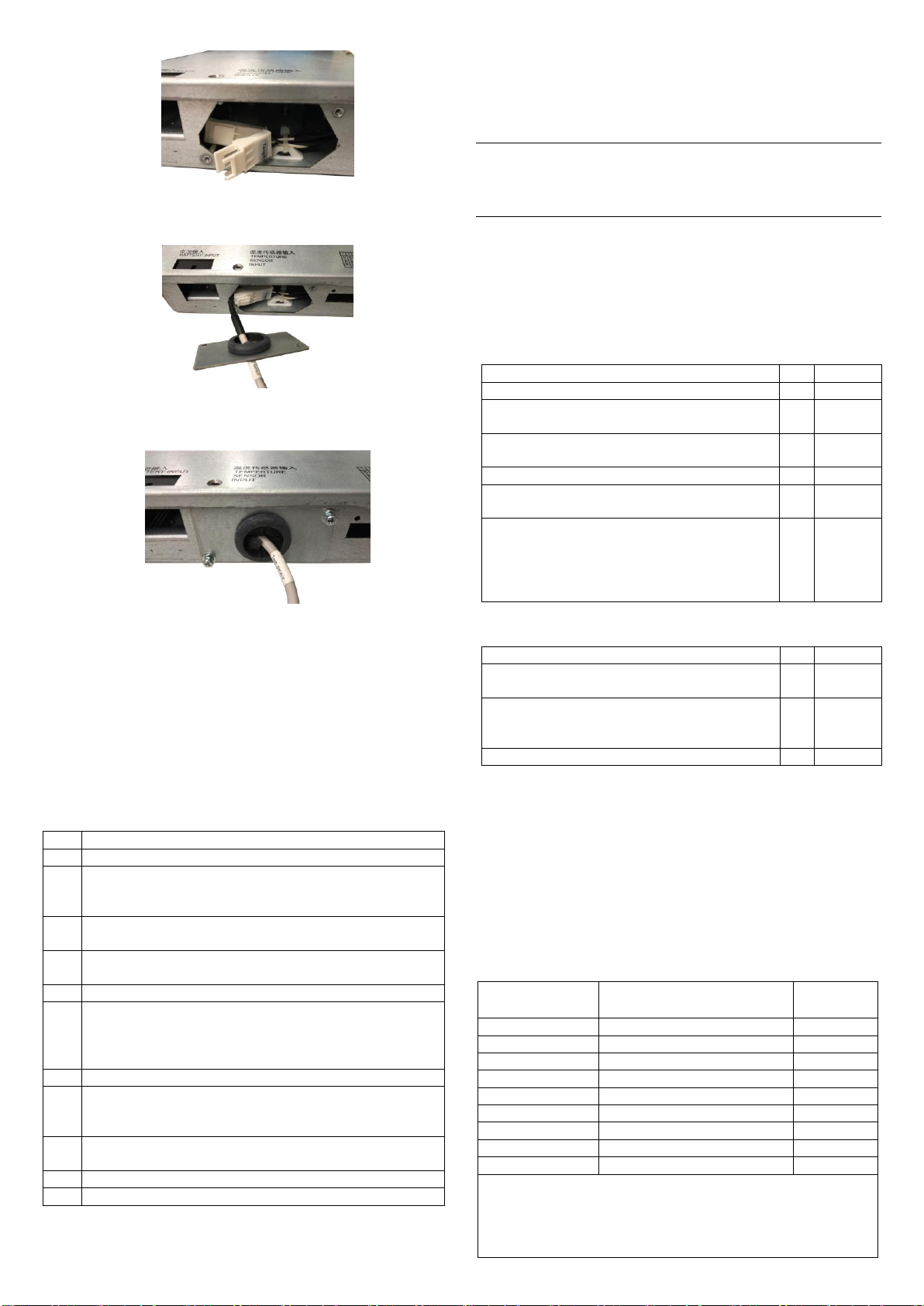
Figure 2-16 Position of white terminal
4. Plug the end of Temp. cable into the whitel terminal, and put the inserted
terminal into the inside of the subrack, as shown in Figure 2-17.
Figure 2-17 Connecting the terminal
5. Fix the two screws of the cover plate, and attach the Temp. cable onto the battery pack,
as shown in Figure 2-18.
Figure 2-18 Fixing the screws
For NetSure 2100 A31-S3 configuration, the corresponding controller is M831A, and a
battery temperature compensation cable is configured. Take out the Temp. cable from the
accessory at the site and connect the cable as above. When configuring one Temp. cable,
one end of the Temp. cable is connected to the ‘Temp.1’ terminal, and the other end is
attached to the battery pack. When configuring two Temp. cables, connect one end of the
Temp. cables to the ‘Temp1’ and ‘Temp2’ terminals respectively. The other end of Temp1
is attached to the battery pack, and the other end of Temp2 cable is pasted in the
corresponding position according to actual order requirements.
2.5 Installation Check
After the installation, you should carry out the inspection procedures given in Table 2-3.
Table 2-3 Installation check list
Check that the power system is horizontally, vertically and steadily fixed
Check that all the bolts are tightened, especially those in electrical
connections. Check that the bolts have plain washers and spring washers and
are not reversed
Check that there are no unwanted materials inside the cabinet and clear up
the unwanted materials
Check that the power system is intact. If there are scratches, paint them
immediately with antirust paint to prevent corrosion
Check the correctness of all MCBs and cables specifications
Check the correctness of input and output cable connection, and
communication between the power system and the system grounding. Make
sure that all the cable connections are firm and reliable and the cable binding
is tidy and normative
Check the correctness of the battery strings polarities
Measure the resistance value between the positive terminal and negative
terminal and phase- to - phase resistance value in the AC loop. Make sure that
there is no short-circuit
Check the AC input and distribution. Check that the color of the AC cables is
normative, the cables are laid stably, and the safety labels are complete
Check that the rectifiers are clipped tightly
Check that all the MCBs are switched off
3 Testing
During testing, the corresponding safety regulations must be observed, and the testing
procedures should be followed strictly. The system has been tested before delivery, the
user does not need to carry on the field testing.
3.1 Testing Distribution Unit And Rectifiers
Note
Before the test, inform the chief manufacturer representative. Only trained electrical
engineer can maintain and operate this equipment. In operation, the installation
personnel are not allowed to wear conductive objects such as watches, bracelets, bangles
and rings.
During operation, parts of this equipment carry hazardous voltage. Wrong operation may
result in severe or fatal injuries and property damage. Before the test, Installation check
must be done before testing. Then the batteries can be charged for the first time.
Make sure that the upstream AC output MCBs and load MCBs inside the subrack are
switched off. Make sure that all the devices are properly installed.
Please check the power system according to below listed items.
Startup preparations
Make sure that all the MCBs are switched off.
Measure the AC input voltage. Make sure the input voltage is
within the allowable range.
Make sure that the communication and dry contact alarm output
cable are connected to the monitoring board
Make sure that the temperature sensor is installed correctly
Use a voltmeter to measure the battery string voltage and make
sure the battery polarities are correct
Check with an ohmmeter that there is no short circuit between
the positive & negative terminal of DC output, between the
positive & negative battery poles or AC input terminals (Note:
Pull out all modules before the check and restore them after the
check)
Switch on the system AC output MCB, the green LED on the
rectifier will be on after a certain delay
Switch on the load MCB. Use a multimeter to check the voltage
of both ends of load, if it shows 53.5V ± 0.5V, the voltage is
normal
Switch on the battery MCB
3.2 Basic Settings
The parameters of the power system are set at the factory, and the factory default setting
can meet the normal use of the power system. Users can modify the parameters (like AC
over/under-voltage point, DC over/under-voltage point and so on) of the power system
through background software. Users can also reset the commonly used parameters based
on actual needs through LCD screen of the controller. When setting the system
parameters, the user must enter the correct password before setting the parameters for
the controller. For NetSure 2100 A31-S2 configuration, the password of M225S controller
is 1.
The parameters that users can check and set are listed in Table 3-1.
Table 3-1 Settable parameters of power system
42V ~ 58V (lower than boost voltage)
42V ~ 58V (higher than float voltage)
Load disconnect or alarm output
Note:
1. The battery protection voltage should be set according to battery manufacturer
requirement.
2. If iron lithium battery is configured by user, set relevant charging parameters
according to the requirements of the battery manufacturers