Deltran Battery Tender Selectable User manual

1
IMPORTANT SAFETY INSTRUCTIONS
1) SAVE THESE INSTRUCTIONS – THIS MANUAL CONTAINS IMPORTANT SAFETY
AND OPERATING INSTRUCTIONS.
2) WORKING IN VICINITY OF A LEAD-ACID BATTERY IS DANGEROUS. BATTERIES
GENERATE EXPLOSIVE GASES DURING NORMAL BATTERY OPERATION. FOR
THIS REASON, IT IS OF UTMOST IMPORTANCE THAT YOU FOLLOW THE
INSTRUCTIONS EACH TIME YOU USE THE CHARGER, AND THAT YOU READ AND
FOLLOW THE INSTRUCTIONS PROVIDED EXACTLY.
3) TO REDUCE THE RISK OF BATTERY EXPLOSION, FOLLOW THESE
INSTRUCTIONS AND THOSE MARKED ON THE BATTERY.
4) NEVER SMOKE OR ALLOW AN OPEN SPARK OR FLAME IN THE VICINITY OF THE
BATTERY OR ENGINE.
5) USE CHARGER FOR CHARGING A LEAD-ACID BATTERY ONLY. IT IS NOT
INTENDED TO SUPPLY POWER TO AN EXTRA-LOW-VOLTAGE ELECTRICAL
SYSTEM OR TO CHARGE DRY-CELL BATTERIES. CHARGING DRY-CELL
BATTERIES MAY CAUSE THEM TO BURST AND CAUSE INJURY TO PERSONS AND
DAMAGE TO PROPERTY.
6) NEVER CHARGE A FROZEN BATTERY.
7) IF IT IS NECESSARY TO REMOVE THE BATTERY FROM VEHICLE TO CHARGE IT,
ALWAYS REMOVE GROUNDED TERMINAL FROM THE BATTERY FIRST. MAKE
SURE ALL ACCESSORIES IN THE VEHICLE ARE OFF IN ORDER TO PREVENT AN
ARC.
8) STUDY ALL BATTERY MANUFACTURE’S SPECIFIC PRECAUTIONS SUCH AS
REMOVING OR NOT REMOVING CELL CAPS WHILE CHARGING AND
RECOMMENDED RATES OF CHARGE.
9) FOR A CHARGER HAVING AN OUTPUT VOLTAGE SELECTOR SWITCH, REFER TO
THE CAR OWNER’S MANUAL IN ORDER TO DETERMINE THE VOLTAGE OF THE
BATTERY AND TO MAKE SURE THE OUTPUT VOLTAGE IS SET AT THE CORRECT
VOLTAGE. IF AN OUTPUT VOLTAGE SELECTOR SWITCH IS NOT PROVIDED, DO
NOT USE THE BATTERY CHARGER UNLESS THE BATTERY VOLTAGE MATCHES
THE OUTPUT VOLTAGE RATING OF THE CHARGER.
10) NEVER PLACE THE CHARGER DIRECTLY ABOVE THE BATTERY BEING
CHARGED; GASES OR FLUIDS FROM THE BATTERY WILL CORRODE AND
DAMAGE THE CHARGER. LOCATE THE CHARGER AS FAR AWAY FROM THE
BATTERY AS THE DC CABLES PERMIT.
11) DO NOT OPERATE CHARGER IN A CLOSED-IN AREA OR RESTRICT VENTILATION
IN ANY WAY.
12) CONNECT AND DISCONNECT DC OUTPUT CLIPS ONLY AFTER SETTING ANY
CHARGER SWITCHES TO THE OFF POSITION AND REMOVING AC CORD FROM
THE ELECTRIC OUTLET. NEVER ALLOW CLIPS TO TOUCH EACH OTHER.
13) FOLLOW THESE STEPS WHEN BATTERY IS INSTALLED IN VEHICLE. A SPARK
NEAR A BATTERY MAY CAUSE A BATTERY EXPLOSION. TO REDUCE THE RISK
OF A SPARK NEAR A BATTERY:
a. POSITION AC AND DC CORDS TO REDUCE RISK OF DAMAGE BY HOOD,
DOOR, OR MOVING ENGINE PART;
Deltran Battery TenderSelectable
Designed for six-cell lead-acid batteries from 1.2 – 200Ah
and three-cell lead-acid batteries from 1.2 – 200Ah
P/N 392-0330-RA 2
b. STAY CLEAR OF FAN BLADES, BELTS, PULLEYS, AND OTHER PARTS THAT
CAN CAUSE INJURY TO PERSONS;
c. CHECK POLARITY OF BATTERY POSTS. A POSITIVE (POS, P, +) POST
USUALLY HAS A LARGER DIAMETER THAN A NEGATIVE (NEG, N, -) POST;
d. DETERMINE WHICH POST OF THE BATTERY IS GROUNDED (CONNECTED) TO
THE CHASSIS. IF NEGATIVE POST IS GROUNDED TO CHASSIS (AS IN MOST
VEHICLES), SEE ITEM (e). IF POSITIVE POST IS GROUNDED TO THE CHASSIS,
SEE ITEM (f);
e. FOR A NEGATIVE-GROUNDED VEHICLE, CONNECT THE POSITIVE (RED) CLIP
FROM BATTERY CHARGER TO POSITIVE (POS, P, +) UNGROUNDED POST OF
BATTERY. CONNECT THE NEGATIVE (BLACK) CLIP TO VEHICLE CHASSIS OR
ENGINE BLOCK AWAY FROM BATTERY. DO NOT CONNECT CLIP TO
CARBURETOR, FUEL LINES, OR SHEET-METAL BODY PARTS. CONNECT TO A
HEAVY GAUGE METAL PART OF THE FRAME OR ENGINE BLOCK;
f. FOR A POSITIVE-GROUNDED VEHICLE, CONNECT THE NEGATIVE (BLACK)
CLIP FROM THE BATTERY CHARGER TO THE NEGATIVE (NEG, N, -)
UNGROUNDED POST OF BATTERY. CONNECT THE POSITIVE (RED) CLIP TO
VEHICLE CHASSIS OR ENGINE BLOCK AWAY FROM BATTERY. DO NOT
CONNECT CLIP TO CARBURETOR, FUEL LINES, OR SHEET-METAL BODY
PARTS. CONNECT TO A HEAVY GAUGE METAL PART OF THE FRAME OR
ENGINE BLOCK;
g. CONNECT CHARGER AC SUPPLY CORD TO ELECTRIC OUTLET; AND
h. WHEN DISCONNECTING CHARGER, TURN SWITCHES TO OFF, DISCONNECT
AC CORD, REMOVE CLIP FROM VEHICLE CHASSIS, AND THEN REMOVE CLIP
FROM BATTERY TERMINAL.
14) FOLLOW THESE STEPS WHEN BATTERY IS OUTSIDE VEHICLE. A SPARK NEAR
THE BATTERY MAY CAUSE A BATTERY EXPLOSION. TO REDUCE RISK OF A
SPARK NEAR BATTERY:
a. CHECK POLARITY OF BATTERY POST. A POSITIVE (POS, P, +) BATTERY POST
USUALLY HAS A LARGER DIAMETER THAN A NEGATIVE (NEG, N, -) POST;
b. ATTACH AT LEAST A 60 CM 6-GAUGE (AWG) INSULATED BATTERY CABLE TO
A NEGATIVE (NEG, N, -) BATTERY POST;
c. CONNECT THE POSITIVE (RED) CHARGER CLIP TO THE POSITIVE (POS, P, +)
POST OF BATTERY;
d. POSITION YOURSELF AND THE FREE END OF CABLE AS FAR AWAY FROM
BATTERY AS POSSIBLE, THEN CONNECT THE NEGATIVE (BLACK) CHARGER
CLIP TO FREE END OF CABLE;
e. DO NOT FACE BATTERY WHEN MAKING FINAL CONNECTION;
f. CONNECT CHARGER AC SUPPLY CORD TO ELECTRICAL OUTLET; AND
g. WHEN DISCONNECTING CHARGER, ALWAYS DO SO IN REVERSE SEQUENCE
OF CONNECTING PROCEDURE AND BREAK FIRST CONNECTION WHILE
STANDING AS FAR AWAY AS FROM BATTERY AS PRACTICAL.
15) USE OF AN ADAPTER IS NOT ALLOWED IN CANADA. IF A GROUNDING TYPE
RECEPTACLE IS NOT AVAILABLE, DO NOT USE APPLIANCE UNTIL THE PROPER
OUTLET IS INSTALLED BY A QUALIFIED ELECTRICIAN.

3
USER INSTRUCTIONS
AUTOMATIC CHARGING AND BATTERY STATUS MONITORING:
Battery Tender® chargers are completely automatic and may be left
connected to both AC power and to the battery that it is charging for long
periods of time. The charger output power, voltage, and current depends
on the condition of the battery it is charging. Battery Tender® chargers have
several status LED indicators that provide a visual means to determine the
operating mode of the charger and hence the condition of the battery
connected to the charger.
When AC power is first applied to the charger all of the LEDs will illuminate
for two to three seconds before starting the charge sequence listed below.
The two battery level status LED indicator lights (Amber LED 1, Green LED
3) are available to determine whether the charger is operating in one of the
four primary charge modes:
1) Qualification/Initialization mode: The Monitor Circuit verifies
appropriate battery voltage levels and good electrical continuity
between the battery and the charger DC output.
2) Bulk mode (full charge, constant current, battery is 0% to 80%
charged)
3) Absorption mode (high constant voltage, battery is 80% to 100%
charged).
4) Storage/float maintenance mode (low constant voltage, battery is
100% to 103% charged).
When the battery is fully charged, the battery level status Green LED (3)
indicator will turn solid green and the charger will switch to a storage/float
maintenance charge mode. The Battery Tender® charger will automatically
monitor and maintain the battery at full charge.
4
BATTERY VOLTAGE SELECT BUTTON
The Battery Tender® charger has a “SELECT” button which allows you to
switch between charging a 6-volt battery or a 12-volt battery.
The battery voltage can be selected once the charger has AC power
applied and before the charger is connected to the battery.
Once the charger has AC power and is also connected to the battery the
voltage (12V or 6V) selection cannot be changed. To change the mode,
disconnect the battery from the charger.
If the AC power is interrupted the charger will resume charging at the last
battery voltage setting used.
The charger can also detect if the incorrect battery voltage has been
selected once the connection has been made to the battery. One of the
Green LEDs (LED 1 or 2) located next the 12V or 6V symbol will flash
preventing the charge cycle from starting. In order to begin a new charge
cycle, reset the charger by disconnecting it from the AC supply as well as
the wrong or defective battery for 7-10 seconds. Reconnect the AC supply
and the charger will be ready for a new charge cycle.
ATTENTION: The Battery Tender®CHARGER HAS A SPARK FREE
CIRCUITRY. The output alligator clips or ring terminals will not spark when
they are touched together. The Battery Tender® charger will not produce an
output voltage until it senses at least 3 volts from the battery. It must be
connected to a battery with the correct polarity before it will start charging a
battery. Therefore, if you plug the AC power cord into an AC power outlet,
and if the output alligator clips or ring terminals are not connected to a
battery, and if you touch the alligator clips or ring terminals together, there
will be no electrical spark.
NOTE:
THE OUTPUT CLIPS OR RING TERMINALS MUST BE CONNECTED TO
A BATTERY BEFORE THE CHARGER CAN PRODUCE AN OUTPUT
VOLTAGE.
TIME REQUIRED TO CHARGE A BATTERY:
The Battery Tender®charges at a rate of 3.0 amps or 3 amp-hours per
hour. Therefore, a fully discharged 15 amp-hour battery will take
approximately 4 hours to recharge to 80% capacity.

5
WORKING WITH A DEAD BATTERY OR A BATTERY WITH A VERY
LOW VOLTAGE:
If you try to charge a dead battery having a voltage below 3 volts, the
Battery Tender®charger will not start. An internal safety circuit prevents the
charger from generating any output voltage unless it senses at least 3 volts
at the charger output. In this situation, the amber LED will continue to flash,
indicating that a charge has not been initiated.
NOTE:
If a 12-volt, lead-acid battery has an output voltage of less than 9 volts
when it is at rest, when it is neither being charged nor supplying electrical
current to an external load, there is a good chance that the battery is
defective. As a frame of reference, a fully charged 12-volt, lead-acid
battery will have a rest-state, no-load voltage of approximately 12.9 volts.
A fully discharged 12-volt, lead-acid battery will have a rest-state, no-load
voltage of approximately 11.4 volts. That means that a voltage change of
only 1.5 volts represents the full range of charge 0% to 100% on a 12-Volt,
lead-acid battery. Depending on the manufacturer, and the age of the
battery, the specific voltages will vary by a few tenths of a volt, but the 1.5-
volt range will still be a good indicator of the battery charge %.
STATUS INDICATING LIGHT: If the light is not lit, then the battery is
not properly connected and/or the charger is not plugged into AC
power. The following describes light operation:
AMBER LIGHT FLASHING (Amber LED 1) – The amber LED
flashing indicates that the battery charger has AC power available
and that the microprocessor is functioning properly. If the amber
LED continues to flash, then either the battery voltage is too low
(less than 3 volts) or the output alligator clips or ring terminals are
not connected correctly.
AMBER LIGHT ON STEADY (Amber LED 1) – Whenever the
amber LED is on steady, a battery is connected properly and the
charger is charging the battery. The amber LED will remain on until
the charger completes the charging stage.
GREEN LIGHT FLASHING (Green LED 3) – When the green LED
is flashing and the amber LED (Amber LED 1) is solid the battery is
greater than 80% charged and may be removed from the charger
and used if necessary. Whenever possible, leave the battery on
charge until the green light is solid.
GREEN LIGHT ON STEADY (Green LED 3) – When the green
LED burns steady, the charge is complete and the battery can be
returned to service if necessary. It can also stay connected to
maintain the battery for an indefinite period of time
6
TROUBLESHOOTING
1) If the charger does not turn on and none of the LEDs illuminate.
a. Check to make sure the AC outlet is supplying power by plugging
in a lamp, an appliance, or a voltage meter.
2) The green LED (3) comes on immediately when charging a discharged
battery.
a. The battery is probably defective, take the battery to the dealer to
be tested.
3) When charging a battery the green LED never comes on.
a. The battery may be defective, take the battery to the dealer to be
tested.
b. The battery has an excessive current draw, remove or disconnect
the battery from the equipment.
4) The amber LED continues to flash even with a connection to the
battery:
a. Check the fuse in the accessory cable.
5) 12V green LED is flashing.
a. The battery is damaged or the incorrect battery voltage has been
selected.
6) 6V green LED is flashing.
a. The battery is damaged or the incorrect battery voltage has been
selected.
7) Amber and Green LED are toggling.
a. Reverse polarity connection to the battery.
b. The chargers safety timer has activated due to the battery not
reaching its optimal voltage. The battery may be defective, take
the battery to the dealer to be tested.
FCC Warning
Title 47 Subpart, 15.105(b)
Note: This equipment has been tested and found to comply with the limits for a
class B digital device, pursuant to part 15 of the FCC Rules. These limits are
designed to provide reasonable protection against harmful interference in
residential installation. This equipment generates, uses and can radiate radio
frequency energy and, if not installed and used in accordance with the instructions,
may cause harmful interference to radio television reception, which can be
determined by tuning the equipment off and on, the user is encouraged to try to
correct the interference by one or more of the following measures:
- Reorient or relocate the receiving antenna.
- Increase the separation between the equipment and receiver.
- Connect the equipment into an outlet on a circuit different from that to
which the receiver is connected.
- Consult the dealer or an experienced radio/TV technician for help.

7
ICES-001: Industrial, Scientific, and Medical (ISM) Radio
Frequency Generators
This product has been tested with the listed standards and found to be compliant
with the Code of Industry Canada ES-001 and the measurement Procedure
according to CISPR 11.
CAN ICES-1/NMB-1
8
INSTRUCTIONS IMPORTANTES CONCERNANT LA
SÉCURITÉ
1) CONSERVER CES INSTRUCTIONS. CE MANUEL CONTIENT DES
INSTRUCTIONS IMPORTANTES CONCERNANT SUR LA SÉCURITÉ ET LE
FONCTIONNEMENT.
2) IL EST DANGEREUX DE TRAVAILLER À PROXIMITÉ D’UNE BATTERIE AU
PLOMB. LES BATTERIES PRODUISENT DES GAZ EXPLOSIFS EN
SERVICE NORMAL. IL EST AUSSI IMPORTANT DE TOUJOURS RELIRE
LES INSTRUCTIONS AVANT D’UTILISER LE CHARGEUR ET DE LES
SUIVRE À LA LETTRE.
3) POUR RÉDUIRE LE RISQUE D’EXPLOSION, LIRE CES INSTRUCTIONS ET
CELLES QUI FIGURENT SUR LA BATTERIE.
4) NE JAMAIS FUMER PRÈS DE LA BATTERIE OU DU MOTEUR ET ÉVITER
TOUTE ÉTINCELLE OU FLAMME NUE À PROXIMITÉ DE CES DERNIERS.
5) UTILISER LE CHARGEUR POUR CHARGER UNE BATTERIE AU PLOMB
UNIQUEMENT. CE CHARGEUR N’EST PAS CONÇU POUR ALIMENTER UN
RÉSEAU ÉLECTRIQUE TRÈS BASSE TENSION NI POUR CHARGER DES
PILES SÈCHES. LE FAIT D’UTILISER LE CHARGEUR POUR CHARGER
DES PILES SÈCHES POURRAIT ENTRAÎNER L’ÉCLATEMENT DES PILES
ET CAUSER DES BLESSURES OU DES DOMMAGES;
6) NE JAMAIS CHARGER UNE BATTERIE GELÉE.
7) S’IL EST NÉCESSAIRE DE RETIRER LA BATTERIE DU VÉHICULE POUR
LA CHARGER, TOUJOURS DÉBRANCHER LA BORNE DE MISE À LA
MASSE EN PREMIER. S’ASSURER QUE LE COURANT AUX
ACCESSOIRES DU VÉHICULE EST COUPÉ AFIN D’ÉVITER LA
FORMATION D’UN ARC.
8) PRENDRE CONNAISSANCE DES MESURES DE PRÉCAUTION
SPÉCIFIÉES PAR LE FABRICANT DE LA BATTERIE, P. EX., VÉRIFIER S‘IL
FAUT ENLEVER LES BOUCHONS DES CELLULES LORS DU
CHARGEMENT DE LA BATTERIE, ET LES TAUX DE CHARGEMENT
RECOMMANDÉS.
9) SI LE CHARGEUR COMPORTE UN SÉLECTEUR DE TENSION DE SORTIE,
CONSULTER LE MANUEL DE L’USAGER DE LA VOITURE POUR
DÉTERMINER LA TENSION DE LA BATTERIE ET POUR S’ASSURER QUE
LA TENSION DE SORTIE EST APPROPRIÉE. SI LE CHARGEUR N’EST PAS
MUNI D’UN SÉLECTEUR, NE PAS UTILISER LE CHARGEUR À MOINS QUE
LA TENSION DE LA BATTERIE NE SOIT IDENTIQUE À LA TENSION DE
SORTIE NOMINALE DU CHARGEUR.
10) NE JAMAIS PLACER LE CHARGEUR DIRECTEMENT SOUS LA BATTERIE
À CHARGER OU AU-DESSUS DE CETTE DERNIÈRE. LES GAZ OU LES
FLUIDES QUI S’ÉCHAPPENT DE LA BATTERIE PEUVENT ENTRAÎNER LA
CORROSION DU CHARGEUR OU L’ENDOMMAGER. PLACER LE
CHARGEUR AUSSI LOIN DE LA BATTERIE QUE LES CABLES C.C. LE
PERMETTENT.
11) NE PAS FAIRE FONCTIONNER LE CHARGEUR DANS UN ESPACE CLOS
ET/OU NE PAS GÊNER LA VENTILATION.
Deltran Battery TenderSelectable
Développé pour des batteries acide-plomb à six
cellules de 1,2 – 200 Ah, trois-cellules de 1,2 – 200 Ah.

9
12) METTRE LES INTERRUPTEURS DU CHARGEUR HORS CIRCUIT ET
RETIRER LE CORDON C.A. DE LA PRISE AVANT DE METTRE ET
D’ENLEVER LES PINCES DU CORDON C.C. S’ASSURER QUE LES
PINCES NE SE TOUCHENT PAS.
13) SUIVRE LES ÉTAPES SUIVANTES LORSQUE LA BATTERIE SE TROUVE
DANS LE VÉHICULE. UNE ÉTINCELLE PRÈS DE LA BATTERIE POURRAIT
PROVOQUER L’EXPLOSION DE CETTE DERNIÈRE. POUR RÉDUIRE LE
RISQUE D’ÉTINCELLE À PROXIMITÉ DE LA BATTERIE :
a. PLACER LES CORDONS C.A. ET C.C. DE MANIÈRE À ÉVITER QU’ILS
SOIENT ENDOMMAGÉS PAR LE CAPOT, UNE PORTIÈRE OU LES
PIÈCES EN MOUVEMENT DU MOTEUR;
b. FAIRE ATTENTION AUX PALES, AUX COURROIES ET AUX POULIES
DU VENTILATEUR AINSI QU’À TOUTE AUTRE PIÈCE SUSCEPTIBLE
DE CAUSER DES BLESSURES;
c. VÉRIFIER LA POLARITÉ DES BORNES DE LA BATTERIE. LE
DIAMÈTRE DE LA BORNE POSITIVE (POS, P, +) EST GÉNÉRALEMENT
SUPÉRIEUR À CELUI DE LA BORNE NÉGATIVE (NÉG, N, –);
d. DÉTERMINER QUELLE BORNE EST MISE À LA MASSE (RACCORDÉE
AU CHÂSSIS). SI LA BORNE NÉGATIVE EST RACCORDÉE AU
CHÂSSIS (COMME DANS LA PLUPART DES CAS), VOIR LE POINT (e).
SI LA BORNE POSITIVE EST RACCORDÉE AU CHÂSSIS, VOIR LE
POINT (f);
e. SI LA BORNE NÉGATIVE EST MISE À LA MASSE, RACCORDER LA
PINCE POSITIVE (ROUGE) DU CHARGEUR À LA BORNE POSITIVE
(POS, P, +) NON MISE À LA MASSE DE LA BATTERIE. RACCORDER LA
PINCE NÉGATIVE (NOIRE) AU CHÂSSIS DU VÉHICULE OU AU
MOTEUR, LOIN DE LA BATTERIE. NE PAS RACCORDER LA PINCE AU
CARBURATEUR, AUX CANALISATIONS D’ESSENCE NI AUX PIÈCES
DE LA CARROSSERIE EN TÔLE. RACCORDER À UNE PIÈCE DU
CADRE OU DU MOTEUR EN TÔLE DE FORTE ÉPAISSEUR;
f. SI LA BORNE POSITIVE EST MISE À LA MASSE, RACCORDER LA
PINCE NÉGATIVE (NOIRE) DU CHARGEUR À LA BORNE NÉGATIVE
(NÉG, N, –) NON MISE À LA MASSE DE LA BATTERIE. RACCORDER
LA PINCE POSITIVE (ROUGE) AU CHÂSSIS DU VÉHICULE OU AU
MOTEUR, LOIN DE LA BATTERIE. NE PAS RACCORDER LA PINCE AU
CARBURATEUR, AUX CANALISATIONS D’ESSENCE NI AUX PIÈCES
DE LA CARROSSERIE EN TÔLE. RACCORDER À UNE PIÈCE DU
CADRE OU DU MOTEUR EN TÔLE DE FORTE ÉPAISSEUR;
g. BRANCHER LE CORDON D’ALIMENTATION C.A. DU CHARGEUR;
h. POUR INTERROMPRE L’ALIMENTATION DU CHARGEUR, METTRE
LES INTERRUPTEURS HORS CIRCUIT, RETIRER LE CORDON C.A. DE
LA PRISE, ENLEVER LA PINCE RACCORDÉE AU CHÂSSIS ET EN
DERNIER LIEU CELLE RACCORDÉE À LA BATTERIE.
14) SUIVRE LES ÉTAPES SUIVANTES LORSQUE LA BATTERIE EST À
L’EXTÉRIEUR DU VÉHICULE. UNE ÉTINCELLE PRÈS DE LA BATTERIE
POURRAIT PROVOQUER L’EXPLOSION DE CETTE DERNIÈRE. POUR
RÉDUIRE LE RISQUE D’ÉTINCELLE À PROXIMITÉ DE LA BATTERIE :
a. VÉRIFIER LA POLARITÉ DES BORNES DE LA BATTERIE. LE
DIAMÈTRE DE LA BORNE POSITIVE (POS, P, +) EST GÉNÉRALEMENT
SUPÉRIEUR À CELUI DE LA BORNE NÉGATIVE (NÉG, N, –);
b. RACCORDER UN CÂBLE DE BATTERIE ISOLÉ No 6 AWG MESURANT
AU MOINS 60 CM DE LONGUEUR À LA BORNE NÉGATIVE (NÉG, N, –);
c. RACCORDER LA PINCE POSITIVE (ROUGE) À LA BORNE POSITIVE
(POS, P, +) DE LA BATTERIE;
10
d. SE PLACER ET TENIR L’EXTRÉMITÉ LIBRE DU CÂBLE AUSSI LOIN
QUE POSSIBLE DE LA BATTERIE, PUIS RACCORDER LA PINCE
NÉGATIVE (NOIRE) DU CHARGEUR À L’EXTRÉMITÉ LIBRE DU CÂBLE;
e. NE PAS SE PLACER FACE À LA BATTERIE POUR EFFECTUER LE
DERNIER RACCORDEMENT;
f. RACCORDER LE CORDON D’ALIMENTATION C.A. DU CHARGEUR À
LA PRISE;
g. POUR INTERROMPRE L’ALIMENTATION DU CHARGEUR, METTRE
LES INTERRUPTEURS HORS CIRCUIT, RETIRER LE CORDON C.A. DE
LA PRISE, ENLEVER LA PINCE RACCORDÉE AU CHÂSSIS ET EN
DERNIER LIEU CELLE RACCORDÉE À LA BATTERIE. SE PLACER
AUSSI LOIN QUE POSSIBLE DE LA BATTERIE POUR DÉFAIRE LA
PREMIÈRE CONNEXION.
15) L’UTILISATION D’UN ADAPTATEUR EST INTERDITE AU CANADA. SI UNE
PRISE DE COURANT AVEC MISE À LA TERRE N’EST PAS DISPONIBLE
EN FAIRE INSTALLER UNE PAR UN ÉLECTRICIEN QUALIFIÉ AVANT
D’UTILISER CET APPAREIL.
11
MANUEL DE L'UTILISATEUR
CHARGEMENT AUTOMATIQUE ET SURVEILLANCE DE L'ÉTAT DE LA
BATTERIE : Les chargeurs Battery Tender® sont entièrement
automatiques et peuvent être laissés connectés à la fois au courant
alternatif et à la batterie qui est en charge pendant de longues périodes de
temps. La puissance de sortie, la tension et le courant dépendent de l'état
de la batterie qui est en charge. Les chargeurs Battery Tender® ont
plusieurs indicateurs DEL d'état, qui fournissent un moyen visuel afin de
déterminer le mode de fonctionnement du chargeur et donc l'état de la
batterie connectée au chargeur.
Quand le courant alternatif est appliqué au chargeur la première fois,
toutes les DEL s'allument pendant deux ou trois secondes avant de
démarrer la séquence de charge énumérée ci-dessous.
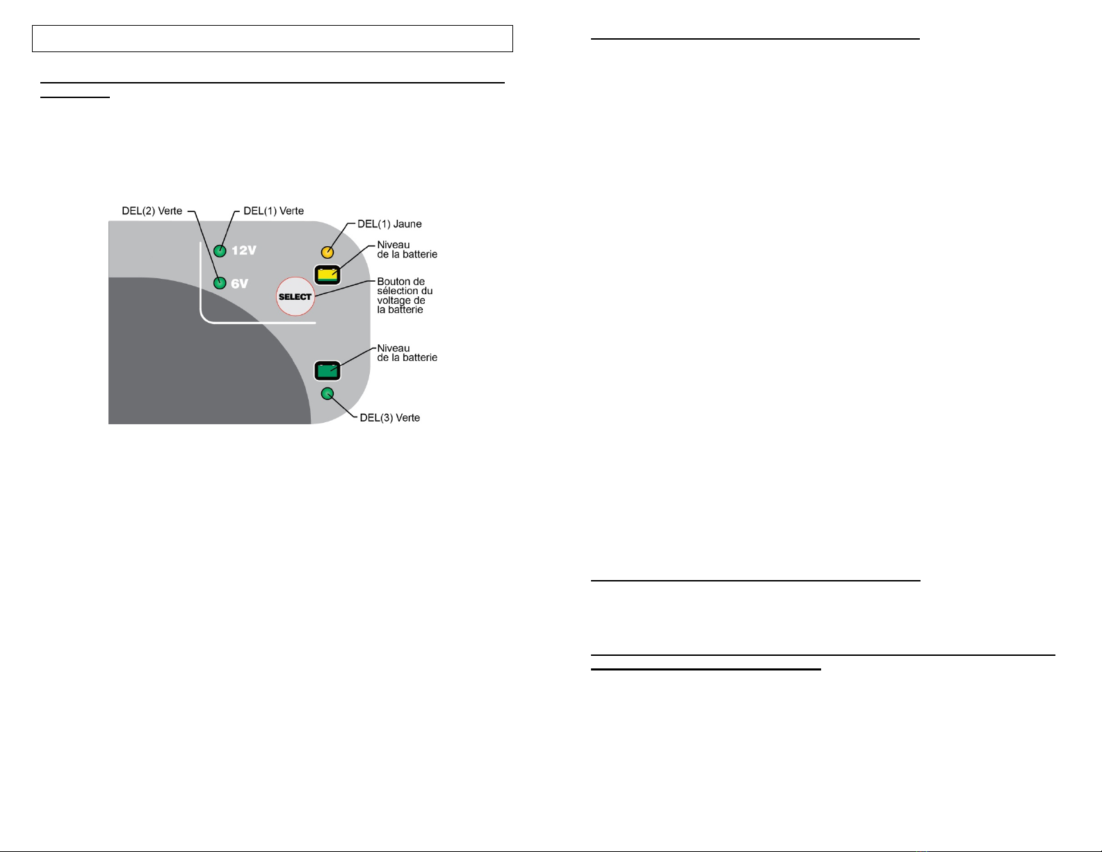
Les deux indicateurs DEL d'état de niveau de batterie (DEL jaune 1, DEL
verte 3) sont disponibles pour déterminer si le chargeur fonctionne dans
l'un des quatre modes de charge primaires :
1) Mode de qualification/initialisation : Le circuit de surveillance
vérifie les niveaux de tension appropriés de batterie et la bonne
continuité électrique entre la batterie et la sortie CC du chargeur.
2) Mode en vrac (pleine charge, courant constant, la batterie est
chargée de 0 % à 80 %)
3) Mode absorption (tension constante élevée, la batterie est
chargée de 80 % à 100 %).
4) Mode maintenance stockage/flottant (tension constante basse,
la batterie est chargée de 100 % à 103 %).
Quand la batterie est entièrement chargée, la DEL verte (3) d'état de
niveau de la batterie s'allume en vert de manière constante et le chargeur
passe en mode de charge de maintenance stockage/flottant. Le chargeur
Battery Tender® va surveiller et maintenir automatiquement la batterie à
pleine charge.
12
BOUTON DE SÉLECTION DE TENSION BATTERIE
Le chargeur Battery Tender® a un bouton « SÉLECT » qui permet de
basculer entre la charge d'une batterie de 6 V et d'une batterie de 12 V.
La tension de la batterie peut être sélectionnée une fois que le chargeur
reçoit le courant alternatif et avant que le chargeur soit branché sur la
batterie.
Une fois que le chargeur reçoit le courant alternatif et est également
connecté à la batterie, la sélection de tension (12 V ou 6 V) ne peut pas
être modifiée. Pour changer le mode, déconnectez la batterie du chargeur.
Si l'alimentation électrique est interrompue, le chargeur va reprendre le
chargement avec le dernier réglage de tension utilisé.
Le chargeur peut également détecter si une tension incorrecte a été
sélectionnée, une fois la connexion établie. Une des DEL verte (DEL 1 ou
2) située à côté du symbole 12 V ou 6 V clignote en empêchant ainsi le
cycle de charge de démarrer. Afin de commencer un nouveau cycle de
charge, réinitialisez le chargeur en le débranchant de l'alimentation CA
ainsi que de la batterie mauvaise ou défectueuse pendant 7 à 10
secondes. Rebranchez l'alimentation CA et le chargeur sera prêt pour un
nouveau cycle de charge.
ATTENTION : LE CHARGEUR Battery Tender®A UN CIRCUIT SANS
ÉTINCELLE. Les pinces crocodiles de sortie ou les cosses ne produiront
pas d'étincelles quand elles se touchent. Le chargeur Battery Tender® ne
produira pas une tension de sortie jusqu'à ce qu'il détecte au moins 3 V de
la batterie. Il doit être raccordé à une batterie en respectant la bonne
polarité avant qu'il commence à charger une batterie. Ainsi, si vous
branchez le cordon d'alimentation sur une prise électrique CA, et si les
pinces crocodiles de sortie ou les cosses ne sont pas connectées à une
batterie, et si vous faites se toucher les pinces crocodiles ou cosses, il y
n'aura aucune étincelle électrique.
REMARQUE :
LES PINCES DE SORTIE OU LES COSSES DOIVENT ÊTRE
RACCORDÉES À UNE BATTERIE AVANT QUE LE CHARGEUR
PUISSE PRODUIRE UNE TENSION DE SORTIE.
TEMPS REQUIS POUR CHARGER UNE BATTERIE :
Le chargeur Battery Tender®charge à raison de 3 ampères-heures ou
3 Ah. Ainsi, une batterie entièrement déchargée de 15 Ah prendra environ
4 heures pour se recharger à 80 % de sa capacité.
TRAVAILLER AVEC UNE BATTERIE À PLAT OU UNE BATTERIE
AVEC UNE TRÈS BASSE TENSION :
Si vous essayez de charger une batterie à plat ayant une tension inférieure
à 3 V, le chargeur Battery Tender®ne démarrera pas. Un circuit interne de
sécurité empêche le chargeur de générer n'importe quelle tension de sortie
à moins qu'il détecte au moins 3 V à la sortie du chargeur. Dans cette
situation, la DEL jaune va continuer à clignoter, indiquant qu'aucune
charge n'a été initiée.

13
REMARQUE :
Si une batterie d'accumulateurs au plomb de 12 V a une tension de sortie
de moins de 9 V lorsqu'elle est au repos, quand elle n'est pas en charge ni
ne fournit du courant électrique à une charge extérieure, il y a de bonnes
chances pour que la batterie soit défectueuse. Comme cadre de
référence, une batterie à accumulateur au plomb de 12 V complètement
chargée aura un état de repos, tension sans charge d'environ 12,9 V. Une
batterie d'accumulateurs au plomb de 12 V complètement déchargée aura
un état de repos, tension sans charge d'environ 11,4 V. Cela signifie qu'un
changement de tension de seulement 1,5 V représente l'ensemble de la
charge de 0 % à 100 % sur une batterie d'accumulateur au plomb de 12 V.
Selon le fabricant et l'âge de la batterie, les tensions spécifiques peuvent
varier de quelques dixièmes de volt, mais la gamme de 1,5 V sera toujours
un bon indicateur du % de charge de la batterie.
TÉMOIN LUMINEUX D'ÉTAT : Si le voyant ne s'allume pas, alors la
batterie n'est pas correctement connectée et/ou le chargeur n'est pas
relié au secteur. Ce qui suit décrit le fonctionnement des témoins
lumineux :
CLIGNOTEMENT TÉMOIN JAUNE (DEL jaune 1) – Le
clignotement de la DEL jaune indique que le chargeur de batterie
dispose de courant alternatif et que le microprocesseur fonctionne
correctement. Si la DEL jaune continue de clignoter, alors soit la
tension de la batterie est trop faible (moins de 3 V) soit les pinces
crocodile ou les cosses ne sont pas connectées correctement.
TÉMOIN JAUNE ALLUMÉ CONSTANT (DEL jaune 1) – Quand la
DEL jaune est allumée en permanence, une batterie est
correctement connectée et le chargeur est en train de charger la
batterie. La DEL jaune restera allumée jusqu'à ce que le chargeur
termine la phase de chargement.
CLIGNOTEMENT TÉMOIN VERT (DEL verte 3) – Lorsque la DEL
verte clignote et que la DEL jaune (DEL jaune 1) est allumée de
manière constante, la batterie est chargée à plus de 80 % et peut
être enlevée du chargeur et utilisée si nécessaire. Quand cela est
possible, laissez la batterie en charge jusqu'à ce que le témoin vert
soit allumé de manière constante.
TÉMOIN VERT CONSTANT (DEL verte 3) – Quand le témoin vert
est allumé de manière constante, la charge est terminée et la
batterie peut être remise en service si nécessaire. Elle peut
également rester connectée pour maintenir la batterie pour une
durée indéterminée
14
DÉPANNAGE
1) Si le chargeur ne s'allume pas et qu'aucune DEL ne s'illumine.
a. Vérifiez que la prise secteur transmet le courant en branchant
une lampe, un appareil ou un voltmètre.
2) La DEL verte (3) s'allume immédiatement lors de la charge d'une batterie
déchargée.
a. La batterie est probablement défectueuse, amenez-la au
concessionnaire pour la faire tester.
3) Lors de la charge d'une batterie, la DEL verte ne s'allume jamais.
a. La batterie peut être défectueuse, amenez-la au concessionnaire
pour la faire tester.
b. La batterie a un appel de courant excessif, retirez ou débranchez
la batterie de l'équipement.
4) La DEL jaune continue de clignoter même avec une connexion à la
batterie :
a. Vérifiez le fusible dans le câble accessoire.
5) La DEL verte 12 V clignote.
a. La batterie est endommagée ou la tension de la batterie qui a été
sélectionnée n'est pas correcte.
6) La DEL verte 6 V clignote.
a. La batterie est endommagée ou la tension de la batterie qui a été
sélectionnée n'est pas correcte.
7) Les DEL jaune et verte basculent.
a. Inversez la polarité de la connexion à la batterie.
b. La minuterie de sécurité des chargeurs s'est activée du fait que la
batterie n'atteint pas sa tension optimale. La batterie peut être
défectueuse, amenez-la au concessionnaire pour la faire tester.
Avertissement de la FCC
Titre 47 Sous-partie, 15.105(b)
Remarque : Cet équipement a été testé et déclaré conforme aux limites d'un
appareil numérique de classe B, selon la partie 15 des règles FCC. Ces limites sont
conçues pour fournir une protection raisonnable contre les interférences nuisibles
dans une installation résidentielle. Cet équipement génère, utilise et peut émettre
de l'énergie radio fréquence et, s'il n'est pas installé et utilisé conformément aux
instructions, peut provoquer des interférences nuisibles à la réception de la radio ou
de la télévision, ce qui peut être déterminé par l'arrêt et la marche de l'appareil,
l'utilisateur est encouragé à essayer de corriger les interférences avec une ou
plusieurs des mesures suivantes :
- Réorientez/déplacez l'antenne de réception.
- Augmentez la distance entre l'équipement et le récepteur.
- Connectez l'équipement à une sortie sur un circuit différent de celui sur
lequel le récepteur est branché.
Consultez le revendeur ou un technicien radio/télévision pour obtenir de
l'aide.
Table of contents
Languages:
Other Deltran Battery Tender Batteries Charger manuals

Deltran Battery Tender
Deltran Battery Tender 022-0227 User manual

Deltran Battery Tender
Deltran Battery Tender WP800 User manual

Deltran Battery Tender
Deltran Battery Tender WP800 Installation instructions manual

Deltran Battery Tender
Deltran Battery Tender Plus User manual

Deltran Battery Tender
Deltran Battery Tender Junior User manual


