DEMA 700 Series User manual

I-776 Page 1of 18
Rev. G29208
(Not all models are shown)
700 SERIES
DAH “Dilution at Hand” Blend Centers
Owners Manual
Basic DAH Blend Center Operation
Warning:Usecarewhenhandlinghazardouschemicalsanduseprotectiveclothing/eyewearasrecommendedbyChemicalManufacturer.
The DAH “Dilution at Hand” blend center is a chemical/water solution dispensing system engineered to dilute
concentrated chemicals utilizing versatile controls and ASSE Standard 1055 Type B approved backflow
prevention devices with 1 and/or 4 GPM flow rate proportioners. Depending on the DAH blend center
equipment, the flow of inlet water and the desired mixture of chemical can be either activated by sliding a lift
button by hand, sliding the lever with the spray bottle, or depressing the trigger on the remote fill gun. Once the
valve control mechanism is activated, the water inlet valve opens allowing water to flow through the backflow
prevention device/proportioner that mixes a chemical/water solution at the desired induction rate with the use of
metering tips.
Bottle & Hose Fill Application: A return spring is used on the sliding lift button and sliding lever to prevent an
accidental overflow of chemical/water solution if unattended (Note: Unless the sliding lift button is in the
“Lock” position). To “Lock” the sliding lift button, slide the button all the way up then push it in towards the
wall. Slowly release the button and it will stay in the “Lock” position. To “Unlock” the button, the button
and/or the lever can be pushed upward to automatically release the locking mechanism.
Remote Fill Application: A return spring is used on the remote gun trigger to prevent an accidental overflow of
chemical/water solution if unattended (Note: Unless the trigger lock is in the “Lock” position). To “Lock” the
remote gun trigger, depress the trigger and slide the lock lever to the right. Slowly release the trigger and it will
stay in the “Lock” position. To “Unlock” the trigger, depress the trigger again to automatically release the
locking mechanism. Sold by DEMA Engineering Company, St. Louis, MO 63122 U.S.A.

I-776 Page 2of 18
Rev. G29208
Getting to Know Your DAH Blend Center
(Some models may not include all items listed below)
1. Sliding Lift Button: The button controls the flow of a chemical/water solution through the outlet hose. The button can be locked
for continuous flow by lifting the button all the way up then pushing it in towards the wall. Slowly release the button and it will
stay in the “Lock” position. To “Unlock” the button, the button and/or the lever can be pushed upward to automatically release
the locking mechanism.
2. Cover: The cover is easily snapped into place for assembly and removed for serviceability. Insert the two lower tabs on the cover
into the lower base pocket features, and then rotate upper cover towards the base until it snaps into place. Push down on upper
cover snap-in lever feature and pull forward on cover for removal.
3. Bucket Fill Outlet Hose: The bucket fill outlet hose is used to fill containers away from the unit by means of the sliding lift
button. The container being filled must be positioned lower than the dispenser.
4. Bucket Fill Outlet Hose Hanger: The wire formed hanger is designed to slide on the end of the bucket fill hose and to be used as
a handgrip. The hanger has a hook feature capable of sliding into the cover pocket feature for storage (See item 8 below).
5. Base: The base is used to mount the unit to the wall and to support the valve body mechanism.
6. Water Inlet Connection: A female ¾ - 11 ½ hose swivel coupling with strainer washer is used to connect the DAH blend center
to the water supply line.
7. Selector Control Knob: Selector knob allows the operator to choose either a desired chemical or amount of chemical dilution.
8. Bucket Fill Outlet Hose Pocket Features: A pocket feature on either side of the cover is used to hang the bucket fill outlet hose
onto the dispenser. The bucket fill outlet hose must be unhooked prior to removing the cover.
9. Sliding Lever: The lever controls the flow of chemical/water solution through the outlet hose by pushing the lever up with the
bottle. If the “Sliding Lift Button” is locked for continuous flow, the lever can be pushed upward to unlock the lift button feature.
10. Bottle Fill Outlet Hose. The bottle fill hose is used to fill spray bottles with minimal foaming.
11. Lever Return Spring: The compression spring returns the lever automatically to shut off the flow of chemical/water solution
unless the lift lever is in the “Lock” position.
12. Backflow Prevention Device: The backflow prevention device prevents any chemical solution from flowing back into the water
supply. The “Action Gap” & “Air Gap” backflow prevention devices are ASSE Standard 1055 Type B approved.
13. Proportioner: The “Action Gap” is used with either a 1 or 4 GPM flow proportioner. The 1 & 4 GPM “Air Gap” backflow
prevention devices have built in proportioners. The 1 GPM proportioners are green and the 4 GPM proportioners are white.
14. *Elbow: The chemical supply tube assembly is connected to the elbow for drawing chemical out of the concentrated bottle.
15. Valve Subassembly: The valve assembly is a watertight valve utilizing high pressure “O-Rings”. The various components are
held together when the valve subassembly is slid into the retaining blades (forks) on the base itself. (Note: The complete valve
assembly must be subassembled then slid into the base or bases as “one” component.)
16. Base Keyhole Mounting Bosses: Each base has two keyhole bosses for mounting the unit to the wall.
17. *Selector Body: One or more chemical supply and foot valve assemblies are connected to the selector body for drawing
concentrated chemical out of one or more containers.
18. Chemical Supply Hose Access Features: The two bottom slot features in the base are used when the blend center is mounted to
the wall whereas the two large holes are used when the blend center is mounted to a wire rack.
19. Remote Fill Outlet Hose/Handle Assembly: The Remote Fill Outlet hose is used to fill containers away from the unit by means
of depressing the trigger. The container being filled must be positioned lower than the dispenser. The remote handle (gun) has a
hook feature capable of sliding into the cover pocket feature for storage (see item 8 above).
20. Trigger: The trigger controls the flow of chemical/water solution through the outlet hose by depressing it.
21. Trigger Lock: The trigger can be locked for continuous flow by depressing the trigger and sliding the lock lever to the right.
Slowly release the trigger and it will stay in the “Lock” position. To “Unlock” the trigger, depress the trigger to automatically
release the locking mechanism.
*The elbow and selector body hose barb features are threaded to accept various size metering tips for controlling the desired chemical
induction flow rate (See section labeled “Metering Tip(s) Selection and Installation” on page 7 for detailed information.)
19
21
20
4
3
2
1
10 14
12
98
7
5
6
13
11
18
17
15
16

I-776 Page 3of 18
Rev. G29208
Table of Contents
Basic DAH Blend Center Operation . . . . . . . . . . . . . . . . . . . . . . . . . . . . . . . . . . . . . . . . . . . . . . . . . . . . . . . .1
Getting to Know Your DAH Blend Center . . . . . . . . . . . . . . . . . . . . . . . . . . . . . . . . . . . . . . . . . . . . . . . . . . .2
Table of Contents . . . . . . . . . . . . . . . . . . . . . . . . . . . . . . . . . . . . . . . . . . . . . . . . . . . . . . . . . . . . . . . . . . . . . . .3
Installation Must Meet Local Plumbing Codes . . . . . . . . . . . . . . . . . . . . . . . . . . . . . . . . . . . . . . . . . . . . . . . .3
ASSE Standard 1055 Type B Approved Components . . . . . . . . . . . . . . . . . . . . . . . . . . . . . . . . . . . . . . . . . . 3
DAH Blend Center Application Requirement . . . . . . . . . . . . . . . . . . . . . . . . . . . . . . . . . . . . . . . . . . . . . . . . .3
Merchandise Returns . . . . . . . . . . . . . . . . . . . . . . . . . . . . . . . . . . . . . . . . . . . . . . . . . . . . . . . . . . . . . . . . . . . .3
Product Warranty . . . . . . . . . . . . . . . . . . . . . . . . . . . . . . . . . . . . . . . . . . . . . . . . . . . . . . . . . . . . . . . . . . . . . . .3
Tools Needed for Mounting DAH Blend Center . . . . . . . . . . . . . . . . . . . . . . . . . . . . . . . . . . . . . . . . . . . . . . .3
Unpacking and Checking Contents . . . . . . . . . . . . . . . . . . . . . . . . . . . . . . . . . . . . . . . . . . . . . . . . . . . . . . . . .4
Installing New DAH Blend Center to the Wall . . . . . . . . . . . . . . . . . . . . . . . . . . . . . . . . . . . . . . . . . . . . . . 4-7
Installing New DAH Blend Center/Rack Assembly to the Wall . . . . . . . . . . . . . . . . . . . . . . . . . . . . . . . . .5-7
Typical DAH Blend Center “Chemical Supply & Hose” Installation . . . . . . . . . . . . . . . . . . . . . . . . . . . . . . .6
Metering Tips(s) Selection and Installation . . . . . . . . . . . . . . . . . . . . . . . . . . . . . . . . . . . . . . . . . . . . . . . . . . .7
DAH Blend Center Proportioner Induction Flow Rate Charts . . . . . . . . . . . . . . . . . . . . . . . . . . . . . . . . . . . . 8
Maintaining and Servicing DAH Blend Center . . . . . . . . . . . . . . . . . . . . . . . . . . . . . . . . . . . . . . . . . . . . .9-12
Disassembling & reassembling the remote fill hose assembly . . . . . . . . . . . . . . . . . . . . . . . . . . . . . . . .9
Checking backflow prevention device/proportioner, metering tip(s), and/or foot valves . . . . . . . . . . 10
Checking water valve malfunction on bottle & hose fill applications . . . . . . . . . . . . . . . . . . . . . . . . . 10
Adding a DAH blend center to an existing DAH blend center . . . . . . . . . . . . . . . . . . . . . . . . . . . .10-12
Trouble Shooting . . . . . . . . . . . . . . . . . . . . . . . . . . . . . . . . . . . . . . . . . . . . . . . . . . . . . . . . . . . . . . . . . . . . . .13
Parts List for DAH Blend Center (Bottle/Hose Fill Applications) . . . . . . . . . . . . . . . . . . . . . . . . . . . 14, 16-17
Parts List for DAH Blend Center (Remote Fill Hose Assembly Application) . . . . . . . . . . . . . . . . . . . . . 15-17
Parts List for DAH Rack Assemblies . . . . . . . . . . . . . . . . . . . . . . . . . . . . . . . . . . . . . . . . . . . . . . . . . . . . . . . 18
Installation Must Meet Local Plumbing Codes
Note: All installations must conform to local plumbing codes and use approved backflow prevention devices. A pressure indicating
tee is to be installed with existing faucets according to local plumbing codes in the state of Wisconsin and any other state that requires
the use of a pressure indicting tee.
ASSE Standard 1055 Type B Approved Components
“Action Gap” & “Air Gap” backflow prevention devices are ASSE Standard 1055 Type B approved.
DAH Blend Center Application Requirement
Water supply pressure should be in the 20-125 psi range and water temperature must not exceed 150°F.
Merchandise Returns
No Merchandise will be Returned for Credit Without DEMA’S Written Permission. Returned Merchandise Authorization Number is
Required in Advance of Return. Product Warranty
DEMA products are warranted against defective material and workmanship under normal use and service for one year from the date of
manufacture. This limited warranty does not apply to any products that have a normal life shorter than one year or failure and damage
caused by chemicals, corrosion, physical abuse, or misapplication. Rubber and synthetic rubber parts such as “o”-rings, diaphragms,
PVC tubing, and gaskets are considered expendable and are not covered under warranty. This warranty is extended only to the
original buyer of DEMA products. If products are altered or repaired without prior approval of DEMA, this warranty is void.
Defective units or parts should be returned to the factory with transportation prepaid. If inspection shows them to be defective, they
will be repaired or replaced without charge, F.O.B. factory. DEMA assumes no liability for damages. Return merchandise
authorization number must be granted in advance of returned units for repair or replacement (See “Merchandise Returns” above).
Tools Needed for Mounting DAH Blend Center
Hammer Drill with 1/4”, 1/8”, 9/32” and 5/32” Diameter Bits
Pliers Medium Phillips Screwdriver
Tape Measure Straight Edge/Level

I-776 Page 4of 18
Rev. G29208
14 5/8
10
13 3/4
18 3/8
45/8
10
3
3
91/8
(Note: All
dimensions
are in inches)
3/4
3
53/83
41/2
WATER INLET
CONNECTION
SEE STEP 2
Unpacking and Checking Contents
Table of Contents
Item Description Qty
ABlend Center or Blend Center/Rack Assembly 1
B Bag of Loose Parts (See table below) 1
C **Outlet Hose **
D Chemical Supply Tube & Foot Valve Assembly *
E DAH Owners Manual 1
F Drip Tray (Only supplied on some DAH Blend Center/Rack Models) *
Note: Save owners manual for servicing and parts information.
Parts in Item “B” (Bag of Loose Parts)
Item Description Qty
G Ceramic Weight
H Screw & Anchor Kit *
I 100-15K Metering Tip Kit *
J Chemical Label *
K Bucket Fill Outlet Hose Hanger (Only on some models) 1
L Key Set (Only supplied on Multiproduct Rack Models) 1
*Quantity varies depending on the model of the DAH blend center.
a. There should be an equal quantity of Items “D” & “G”.
b. Blend Center: 1 #10 hardware kit (Item “H”) per individual unit in blend center.
Blend Center/Rack Assembly: 1 #12 hardware kit (Item “H”).
**Outlet Hose Description for Item “C”
Backflow Prevention
Device/Proportioner Description of Outlet Hose(s) Per
Proportioner Qty
**
“Action Gap”/1 GPM Proportioner Short Hose 1
“Action Gap”/4 GPM Proportioner Long Hose 1
“1 GPM “Air Gap” Proportioner Short Hose 2
“4 GPM “Air Gap” Proportioner Long Hose 1
“Action Gap”/4 GPM
Proportioner/Remote Fill Gun Double Hose w/Remote Gun Assembly
(Note: Already Assembled) 1
4 GPM “Air Gap” Proportioner
Double Hose w/Gun Double Hose w/Remote Gun Assembly
(Note: Already Assembled) 1
Installing New DAH Blend Center to the Wall
1. Evaluating wall spacing for hanging
blend center on wall: Depending on
the number of individual units that are
connected together, wall space must be
closely laid out to make sure there is
adequate room. Be sure to allow a
minimum of 12 inches on both the left
and right hand sides of the blend
center. The added space will be used
for hanging the bucket fill outlet hose,
remote fill gun, and for attaching the
water supply to the blend center. This
will vary depending on the model of
the blend center. (Note: All dimensions
are shown in inches and the sketch
shows the mounting layout for a 4 unit
DAH blend center.)

I-776 Page 5of 18
Rev. G29208
2. Laying out and drilling holes in the wall for mounting the DAH Blend Center: Carefully layout the proper mounting holes on
the wall based on the information in step 1 on previous page using a tape measure and straight edge/level for hanging the blend
center on the wall. (Note: Drill two holes into the wall for each individual unit in the DAH blend center. Drill all of the holes
into the drywall using a 1/4” diameter bit for use with the included #10 x 1” long screw and anchor set. If mounting the blend
center to wood and you do not plan to use the included anchors, drill 1/8” diameter holes.)
3. Getting the water supply line and blend center ready so it can be mounted on the wall: Remove the individual unit cover(s)
by pressing down on the upper cover snap-in lever feature and pulling forward on the cover. (Note: If the blend center is equipped
with a selector valve, the phillips screw holding the selector knob will need to be removed. Save all removed components in a
safe place for re-assembly.) A water supply line must be plumbed up to the right hand side of the DAH blend center using a male
¾ - 11 ½ N.H. hose coupling fitting.
4. Mounting blend center to the wall and connecting the water supply line: Insert the anchors into drilled holes and hammer
them into the wall until they are flush with face of wall. Assemble all of the #10 x 1” long screws with a phillips screwdriver into
the anchors so the screw heads are sticking out of the wall approximately ½”. Carefully align the large section of the keyhole
slots in the blend center base(s) over the screw heads. Once positioned properly, push blend center against the wall over the
screw heads and slide it down until the keyhole slots are resting on the screws. Tighten the screws against the keyhole bosses in
each base. Connect the water supply line to the female swivel garden hose coupling on the blend center and tighten by hand.
(Note: May need to tighten hose coupling another ¼ turn with pliers but Do Not Overtighten.) Water supply pressure should be
in the 20-125 psi range and water temperature must not exceed 150
°
F. Slowly turn on the water supply and check for any leaks.
(Note: See section labeled “Trouble Shooting” on page 13 if any continual leaks are visible.) Mount water supply line to wall
with proper clamp(s) to avoid any damage to the blend center. (Go to step #5 on the next page)
Installing New DAH Blend Center/Rack Assembly to the Wall
1. Evaluating wall spacing for hanging blend center/rack assembly on wall: On the single product rack, allow a minimum of 12
inches on both the left and right hand sides of the rack. On the multiproduct rack, allow a minimum of 4 inches on both the left
and right hand sides of the rack. The added space will be used for attaching the water supply to the blend center. This will vary
depending on the model of the blend center. (Note: All dimensions are shown in inches and the sketch shows the mounting for a
single product and multiproduct rack assembly.)
25 3/8
16
MULTIPRODUCT RACK
(Note: All dimensions are in inches)
SINGLE PRODUCT RACK
19 1/4
11/16
2 7/16
5 5/8
6 1/2
1 5/8
3
7 3/4
(DAH Blend Center not shown)
19 9/16
4 11/16
4 15/16
10 1/8

I-776 Page 6of 18
Rev. G29208
Selector
Foot Valve
Assembly
Ceramic
Weight
Tip
Foot Valve
Assembly
Elbow
Tip
Ceramic
Weight
2. Laying out and drilling holes in the wall for mounting the DAH Blend Center/Rack Assembly: Carefully layout the proper
mounting holes on the wall based on the information in step 1 on previous page using a tape measure and straight edge/level for
hanging the rack assembly on the wall. (Note: Drill four holes into the wall for either DAH rack assembly. Drill all of the holes
into the drywall using a 9/32” diameter bit for use with the included #12 x 1” long screw and anchor set. If mounting the blend
center to wood and you do not plan to use the included anchors, drill 5/32” diameter holes.)
3. Getting the water supply line and blend center ready so it can be mounted on the wall: Remove the individual unit cover(s)
by pressing down on the upper cover snap-in lever feature and pulling forward on the cover. (Note: If the blend center is equipped
with a selector valve, the phillips screw holding the selector knob will need to be removed. Save all removed components in a
safe place for re-assembly.) A water supply line must be plumbed up to the right hand side of the DAH blend center using a male
¾ - 11 ½ N.H. hose coupling fitting.
4. Mounting blend center to the wall and connecting the water supply line: Insert the anchors into drilled holes and hammer
them into the wall until they are flush with face of wall. Carefully align and position the rack over the anchors and assemble all
of the #12 x 1” long screws with a phillips screwdriver into the anchors. Tighten the screws against the rack but DO NOT
OVERTIGHTEN. Connect the water supply line to the female swivel garden hose coupling on the blend center and tighten by
hand. (Note: May need to tighten hose coupling another ¼ turn with pliers but DO NOT OVERTIGHTEN.) Water supply
pressure should be in the 20-125 psi range and water temperature must not exceed 150
°
F. Slowly turn on the water supply and
check for any leaks. (Note: See section labeled “Trouble Shooting” on page 13 if any continual leaks are visible.) Mount water
supply line to wall with proper clamp(s) to avoid any damage to the blend center. Assemble drip tray (if provided) directly below
the bottle fill units by snapping the tabs over the rod (see page 18).
Typical DAH Blend Center
“Chemical Supply & Hose Installation”
5. Metering tip(s) selection and installation for
various chemical induction flow rates: The
chemical induction flow rates through the
proportioners are controlled by individual
metering tips. Select and install the proper tip(s)
depending on the proportioner in the DAH blend
center and based on the Chemical Manufacturer’s
recommendation for desired chemical flow rate or
ratio. (See steps 2 through 4 in the section
labeled “Metering Tip(s) Selection and
Installation” on page 7.)
6. Chemical supply installation and hose
connections:
Slip a ceramic weight over a chemical supply
hose and slide it against the foot valve. Install the
chemical supply tube and foot valve assembly by
sliding the open end of the tube up through the
DAH base and pushing the tube over the barb
located on the right or left side of the
proportioner. Place the concentrated chemical
container inside the rack or on a flat surface.
Slide the foot valve side of the Hose assembly
into the container. Repeat for each proportioner
barb or selector barb. (Note: If it is more
convenient, the open end of the chemical supply
tube can be inserted through the rear surface of
the base especially designed for rack mounted
DAH blend center applications.)
7. Chemical label installation: Individual chemical labels have been supplied for identifying the chemical(s) being used in the
blend center application. Attached the proper chemical label to the cover(s) depending on the blend center. (Note: On selector
applications, be sure to attach the proper chemical name in the corresponding selector positions.)

I-776 Page 7of 18
Rev. G29208
Install Small
Hose First
Then Install
Larger Hose
"Air Gap"
Bottle Fill
1 GPM
(Green)
Bucket Fill
Bottle Fill
Sketch 2
1 GPM
(Green)
Short Hose
"Action
Gap"
Sketch 1
Long
Hose
4 GPM
(White)
Sketch 3
Bucket FillBucket Fill
Closed Loop
Hook Feature
Open Loop
Long Hose
4 GPM
(White)
Open End of
Hose
Sketch 4 Sketch 5
Push hose
against hanger
Hanger
"Action Gap"
Proportioner
1 GPM (Green)
4 GPM (White)
Proportioner
"Air Gap"
8. Outlet hose installation: Select and install the outlet hose(s) according to the proper sketch(s) as follows:
Sketch
#Type of Backflow Prevention
Device/Proportioner Proportioner Flow Rate
& Color of Proportioner Qty & Type of
Outlet Hose(s)
1“Action Gap”/Proportioner 1 GPM - Green Single short hose
2“Action Gap”/Proportioner 4 GPM - White Single long hose
3“Air Gap” Proportioner 1 GPM - Green Two short hoses
4“Air Gap” Proportioner 4 GPM - White Single long hose
5Either Type 4 GPM - White Bucket fill hose hanger
Note: Remote fill hose assembly is preassembled & ready to use.
Slide closed loop end of
hanger onto open end of hose
and place in desired position,
then slip open end of hose
into open loop of hanger
9. Installing cover(s): Insert the two lower tabs on the cover into the lower base pocket features, and then rotate upper cover
towards the base until it snaps into place. (Note: If the blend center is equipped with selector valve, slide the circular hole feature
in the cover over the selector prior to inserting the two lower cover tabs into the lower base pocket features, then rotate upper
cover towards the base until it snaps into place. Slide the knob over the selector valve stem then install the screw with a phillips
screwdriver (do not overtighten). The blend center is now ready for use.
Metering Tip(s) Selection and Installation
Warning:Usecarewhenhandlinghazardouschemicalsanduseprotectiveclothing/eyewearasrecommendedbyChemicalManufacturer.
The chemical induction flow rates are controlled by individual metering tips.
1. Remove cover(s) and selector knob as necessary. Remove all necessary chemical supply tubes.
2. Select the proper chemical induction flow rate table based on the equipment being used on the DAH blend center as follows:
a. Type of Backflow Prevention Device/Proportioner: (“Action Gap” or “Air Gap”)
b. Proportioner Flow Rate: (“ 1 GPM” or “4 GPM”)
(Note: The 1 GPM proportioners are green and the 4 GPM proportioners are white.)
See Table #
On page 8 Type of Backflow Prevention
Device/Proportioner Proportioner Flow Rate
& Color of Proportioner
1 (Left Side) “Action Gap”/Proportioner 1 GPM - Green
1 (Right Side) “Action Gap”/Proportioner 4 GPM - White
2 (Left Side) “Air Gap” Proportioner 1 GPM - Green
2 (Right Side) “Air Gap” Proportioner 4 GPM - White
3. Select the proper tip(s) based on the DAH blend center proportioner and on the Chemical Manufacturer’s recommendation for
desired chemical flow rate or ratio.
Reference information: 1 cps (centipoise) is equal to the viscosity of water, 75 cps is approximately equal to the viscosity of
10 weight motor oil, and 200 cps is approximately equal to the viscosity of most dishwashing detergents.
4. Install or replace the tip(s) into the proportioner elbow barb and/or selector barbs (do not overtighten).
5. Connect all chemical supply tubes. (Note: Always check and make sure the lever will slide freely and there are no tubes rubbing
the lever and resisting its movement if so equipped.)
6. Re-assembly cover(s) and selector knob with screw if so equipped (do not overtighten).

I-776 Page 8of 18
Rev. G29208
DAH Blend Center Proportioner Induction Flow Rate Charts
Table 1: “Action Gap”/Proportioner Induction Flow Rates w/Standard 1/4" Barb and Tubing
(1 GPM Flow Rate Action Gap Proportioner)
Injection Rates For Viscosities Shown (4 GPM Flow Rate Action Gap Proportioner)
Injection Rates For Viscosities Shown
1cps 75cps 200cps 1cps 75cps 200cps
Metering
Tip
Color Oz/Gal Ratio Oz/Gal Ratio Oz/Gal Ratio Oz/Gal Ratio Oz/Gal Ratio Oz/Gal Ratio
Tan 1.03 125-1 0.76 168-1 0.38 333-1 0.33 387-1 0.26 500-1 0.12 1090-1
Orange 1.24 103-1 0.98 130-1 0.53 241-1 0.42 307-1 0.32 430-1 0.17 735-1
Turquoise 1.43 89-1 1.07 119-1 0.61 211-1 0.51 251-1 0.34 382-1 0.19 676-1
Pink 2.47 52-1 1.58 81-1 0.92 139-1 0.78 165-1 0.56 230-1 0.3 422-1
Light Blue* 3.05 42-1 2.1 61-1 1.06 121-1 0.87 147-1 0.67 192-1 0.33 391-1
Brown 3.48 37-1 2.31 55-1 1.15 111-1 0.99 129-1 0.74 174-1 0.37 345-1
Red 4.38 29-1 2.83 45-1 1.23 104-1 1.37 93-1 0.91 141-1 0.44 289-1
White 5.33 24-1 3.1 42-1 1.37 93-1 1.52 84-1 1.04 123-1 0.48 264-1
Green 6.38 20-1 3.63 35-1 1.4 91-1 1.72 74-1 1.22 105-1 0.52 244-1
Blue 6.77 19-1 3.78 34-1 1.45 88-1 2.13 60-1 1.27 101-1 0.54 239-1
Yellow 9.90 13-1 5.1 25-1 1.48 86-1 3.05 42-1 1.71 75-1 0.56 229-1
Black 15.00 9-1 6.54 20-1 1.53 84-1 4.50 28-1 1.96 65-1 0.57 224-1
Purple 24.94 5-1 7.28 18-1 1.57 82-1 7.75 17-1 2.4 53-1 0.59 217-1
Gray 35.94 4-1 8.5 15-1 1.64 78-1 9.86 13-1 2.54 50-1 0.63 204-1
NoTip 73.21 2-1 9.35 14-1 1.87 69-1 19.63 7-1 3.16 40-1 0.67 190-1
Table 2: “Air Gap” Proportioner Induction Flow Rates w/Standard 1/4" Barb and Tubing
164 BAG (1 GPM Flow Rate Air Gap Proportioner)
Injection Rates For Viscosities Shown 163 BAG (4 GPM Flow Rate Air Gap Proportioner)
Injection Rates For Viscosities Shown
1cps 75cps 200cps 1cps 75cps 200cps
Metering
Tip
Color Oz/Gal Ratio Oz/Gal Ratio Oz/Gal Ratio Oz/Gal Ratio Oz/Gal Ratio Oz/Gal Ratio
Tan 1.25 102-1 0.90 142-1 0.60 213-1 0.30 427-1 0.20 640-1 0.15 853-1
Orange 1.70 75-1 1.20 107-1 0.80 160-1 0.40 320-1 0.30 427-1 0.25 512-1
Turquoise 2.15 60-1 1.55 83-1 1.10 116-1 0.60 213-1 0.40 320-1 0.30 427-1
Pink 3.00 43-1 2.00 64-1 1.50 85-1 0.80 160-1 0.50 256-1 0.40 320-1
Light Blue* 3.90 33-1 2.75 47-1 1.80 71-1 1.00 128-1 0.70 183-1 0.45 284-1
Brown 4.55 28-1 3.00 43-1 2.00 64-1 1.20 107-1 0.80 160-1 0.50 256-1
Red 5.80 22-1 3.60 36-1 2.30 56-1 1.50 85-1 0.90 142-1 0.60 213-1
White 7.00 18-1 4.45 29-1 2.70 47-1 1.85 69-1 1.10 116-1 0.70 183-1
Green 7.90 16-1 5.00 26-1 3.00 43-1 2.00 64-1 1.25 102-1 0.80 160-1
Blue 9.80 13-1 5.75 22-1 3.30 39-1 2.50 51-1 1.50 85-1 0.82 156-1
Yellow 14.80 9-1 7.35 17-1 3.55 36-1 4.00 32-1 1.85 69-1 0.90 142-1
Black 20.15 6-1 8.50 15-1 3.70 35-1 5.50 23-1 2.00 64-1 0.94 136-1
Purple 27.80 5-1 9.80 13-1 3.80 34-1 8.80 15-1 2.40 53-1 0.96 133-1
Gray 31.60 4-1 10.50 12-1 3.90 33-1 11.65 11-1 2.50 51-1 1.00 128-1
NoTip 35.70 3.6-1 11.80 11-1 4.50 28-1 16.20 8-1 3.00 43-1 1.20 107-1
Note: All induction flow rates are based on a water pressure of 40 psi.
Leaner dilutions can be achieved by ordering DEMA ultra lean metering tip kit 100-15KU.
*Metering tip color was formerly clear.
Service Note: Standard size ¼” hose barbs and metering tips that come with this model are used for water thin (1cps) products. Ratios as low as
parts-per-million can be achieved with the use of a capillary metering tip. More viscous products (75cps – 200cps) may require larger 3/8” hose
barbs and metering tips. If you are having difficulty achieving the ratio you require, call DEMA and ask for the technical department.

I-776 Page 9of 18
Rev. G29208
Maintaining and Servicing the DAH Blend Center
Caution: Turn off water supply before doing maintenance or servicing.
Warning: Use care when handling hazardous chemicals and use protective clothing/eyewear as recommended by Chemical
Manufacturer. This includes handling of chemical supply and outlet tubes.
Note: Water supply pressure should be in the 20-125 psi range and water temperature must not exceed 150°F.
Disassembling & reassembling the remote fill hose assembly:
1. Remove cover(s) and selector knob as necessary.
2. Removal of the double hose from the proportioner also involves the disconnection of both the clear and blue 1/8” I.D. tubes.
(Note: The 1/8” I.D. tubing is fairly stiff and the hose barbs can be damaged if not handled carefully.)
3. Slide the upper hose clamp on the blue high pressure tubing up above the hose barb. (Note: It is helpful to use a rotational motion
when sliding the hose clamp up.)
4. Unscrew the diaphragm nut in the direction shown on the sketch. (Note: The hose barb on the diaphragm nut will need to rotate
inside the 1/8” I.D. tubing to remove the nut.)
5. Disassemble the elbow from the front of the valve body using a phillips screwdriver. (Note: The elbow is sealed to the valve
body via an o-ring. Be careful not to loose the o-ring.)
6. Loosen the hose clamp holding the double hose to the proportioner. Remove the double hose off of the proportioner using a
steady pulling and rotational motion. Now you can get to the backflow prevention devise/proportioner.
7. Repeat the same steps above in reverse order to reassemble the remote fill hose assembly. Pay special attention to push the
double hose far enough on the proportioner so it lines up with the flat surface of the top hose barb. Also see Detail “A” for proper
installation of the o-ring onto the elbow before reassembling the elbow to the valve body. (Note: Check to see that the diaphragm
is properly seated then hand-tighten the diaphragm nut.)
8. Reassemble cover(s) and selector knob with screw if so equipped. (Do not overtighten.)
HIGH PRESSURE 1/8" I.D. TUBE (BLUE)
Disassemble elbow from valve
body (See Detail "A" for
re-assembling elbow)
LOW PRESSURE 1/8" I.D. TUBE (CLEAR)
Loosen hose clamp enough to slide
hose off of proportioner
REMOTE FILL HOSE ASSEMBLY
(Disassemble both of the 1/8" I.D. tubes
prior to removing double hose)
Slide hose clamp up 1/2"
minimun (Rotating clamp
while sliding it up is helpful)
Unscrew diaphragm nut
as arrow indicates
Diaphragm must be seated
properly before reinstalling
diaphragm nut
#6HI-LO SCREW
Slide clamp over barb
& tighten clamp
FULLYASSEMBLED
Hand tighten
diaphragm nut
Assemble o-ring
against shoulder prior
to installing elbow
DETAIL "A"
Do not kink tube
Slide clamp against
diaphragm nut
DIAPHRAGM NUT Shoulder

I-776 Page 10of 18
Rev. G29208
Checking backflow prevention device/proportioner, metering tip(s), and/or foot valve(s):
1. Remove cover(s) and selector knob as necessary. Remove outlet hoses and chemical supply tubes as necessary. See section
labeled “Disassembling & reassembling the remote fill hose assembly” on previous page for removing the remote fill hose
assembly.
2. Inspect metering tip(s) and foot valve(s) for build up of dried chemical. Inspect air gap proportioner for build up of hard water
mineral deposits on top nozzle or clogging of inlet screens.
3. If clogged, remove these items and soak in hot water. Hard water deposits can be removed by soaking in an off-the-shelf product
such as CLR. Clean clogged passageways with soft brush or other acceptable tools as necessary. (Note: Selector valve or elbow
needs to be disassembled from proportioner before the proportioner can be removed).
4. Replace with clean or new parts as needed.
5. Connect all outlet and chemical supply tubes. (Note: Always check and make sure the lever will slide freely and there are no
tubes rubbing the lever and resisting its movement if so equipped.)
6. Reassemble cover(s) and selector knob with screw if so equipped (do not overtighten).
Checking water valve malfunction on bottle & hose fill applications:
1. Check to see that the lever moves freely up & down. Determine which water valve is malfunctioning if equipped with more than
one valve body.
2. Follow steps 2 through 7 in the section labeled “Adding a DAH blend center to an existing DAH blend center” below for properly
removing the valve subassembly from the base(s).
3. Remove the screw and nylon washer retaining the sliding lever to the water valve body. (Note: Be careful not to let the magnet
fall out of the lever pocket and get lost as the lever is being removed from the valve body.)
4. Remove the enclosing tube nut from the valve body. (Note: Be careful when removing the nut not to lose the plunger, kickoff
spring, enclosing tube or diaphragm).
5. Check for dirt or damage impeding plunger and kickoff spring movement.
6. Inspect the diaphragm, making sure the two small pin holes (bleed holes), located in the diaphragm’s webbing membrane, are
clear to allow the valve to close. If holes are clogged, remove and soak in hot water. Carefully clean clogged passageways to
avoid any damage to the diaphragm.
7. Replace with clean or new parts as needed. Reassemble valve body subassembly per Figure 2 in the section labeled “Parts List
For DAH Blend Center” on page 14. Hand-tighten enclosing tube nut.
8. Reassemble magnet and lever to valve body with nylon washer and screw per Figure 2 in the section labeled “Parts List For DAH
Blend Center” on page 14. Do not overtighten screw.
9. Follow steps 16 through 18 in the section labeled “Adding a DAH blend center to an existing DAH blend center” on page 12 for
properly reassembling the valve subassembly to the base(s) until the blend center is completely assembled.
Adding a DAH blend center to an existing DAH blend center:
1. Evaluate wall spacing for the added DAH blend center (See step 1 in the section labeled “Installing New DAH Blend Center to
the Wall” on page 4).
2. Shut off and disconnect water supply line from blend center. If equipped with a bucket or remote fill outlet hose, carefully
remove the free end of the outlet hose hanging on the cover and set it in a safe place where it won’t get damaged.
3. Remove cover(s) and selector knob from wall mounted blend center as necessary.
4. Remove outlet and chemical supply hoses as necessary. (Note: Don’t disconnect the remote fill hose assembly.)
5. Remove lever return spring(s) located in the upper section of the individual unit(s) as shown in the upper left hand sketch in step 7
on page 11. (Note: Units with the remote fill hose/handle assembly does not have a lever or return spring.)
6. Remove the screw(s) and nylon washer(s) retaining the bottom end of the sliding lever to the base(s) as shown in the upper left
hand sketch in step 7 on page 11. You may need to remove the proportioner(s) so you can get access to the screw(s). (Note:
Selector valve or elbow needs to be disassembled from proportioner before the proportioner can be removed). (Note: Units with
the remote fill hose assembly does not utilize the lever or the screw and nylon washer.)

I-776 Page 11of 18
Rev. G29208
7. Remove the valve body mounting screws from the base(s). Carefully slide the valve subassembly from the base(s) and set it on a
clean and flat surface or table. (Note: Be careful not to separate the parts within the valve subassembly otherwise the o-rings will
need to be removed and reassembled to avoid water leakage. If the parts become separated, the o-rings will be reassembled on
step 15 on the following page.)
8. Open the new DAH blend center carton and check contents (See section labeled “Unpacking and Checking Contents” on page 4).
9. Lay out and drill holes in the wall for mounting the additional DAH blend center (See step 2 in the section labeled “Installing
New DAH Blend Center to the Wall” on page 5).
10. Remove cover(s) and selector knob from the new DAH blend center as necessary.
11. Repeat prior steps 5 through 7 in this section on the new DAH blend center.
12. Insert the anchors into the drilled holes and hammer them into the wall until they are flush with face of wall. Assemble all of the
#10 x 1” long screws into the anchors so the screw heads are sticking out of the wall approximately ½”. Install the base(s) on the
added screws. Drive the screws into the base far enough so the base can’t slide upward and off of the screw heads but loose
enough that the base can move around slightly. (Note: This will allow for base movement when installing the valve subassembly.)
13. At this time, review and determine the position in which each separate valve subassembly needs to be placed in the final valve
subassembly. (Note: Normally the bucket fill outlet hose is located in the most left position due to the convenience of hanging the
free end of the hose on the left side of the blend center cover. In the case where you have two long outlet hoses, they should be
positioned on each end of the dispenser.) Align the two valve subassemblies on the table accordingly and if necessary, valve
bodies may need to be separated from each other to properly position the valves.
14. The cap positioned on the left side of the valve subassembly and the water inlet stem assembly positioned on the right side of the
valve subassembly will be used and can remain assembled. Carefully disassemble the cap and water inlet stem assembly
positioned next to each other (center position of the two valve subassemblies). Also, remove the o-ring at each disassembled
connection. (Note: The o-ring will normally stay in the female end of the separated parts for each connection. The disassembled
cap, water inlet stem assembly, and one o-ring will not be used in the final valve subassembly.)
#8 HI-LO SCREW
(2 valve mounting
screws per valve body)
LEVER
RETURN
SPRING
VALVE SUBASSEMBLY
VALVE
BODY
LEVER
NYLON
WASHER
#8 HI-LO
SCREW
CAP (Radial
position is
important)
BASE
One groove
facing up
One groove
facing down
GROOVE FEATURES
(NOTE: Grooves must align between mating
parts within the valve subassembly. Maintain
groove alignment otherwise o-rings may become
disassembled and could result in water leakage)
BASE
FORK
FEATURES
WATER INLET
STEM ASSEMBLY
(Radial position not
important)
BASE
REMOTE FILL
HOSE APPLICATION
VALVE SUBASSEMBLY
from step 7
Do not
remove cap
VALVE
SUBASSEMBLY from
step 11
BOTTLE FILL
APPLICATION
BOTTLE FILL
APPLICATION
Remove cap/o-ring
Remove water inlet
stem assembly (stem,
coupling, screen
washer, o-ring)
Do not remove
water inlet stem
assembly

I-776 Page 12of 18
Rev. G29208
Align both grooves for
valve body installation
DETAIL "A"
Remove o-ring if present
Alignmost innergroovefor
stemassembly installation
WATERINLETSTEM
ASSEMBLY
(Radial position not
important)
Reinstall
o-ring (see
detail "A")
One groove
facingdown
CAP (Radial
position is
important)
Align innermost
groovefor cap
installation
One groove
facingup
Align two grooves
forassembly
Install o-ring on male boss feature
Install o-ring against first shoulder
MALE BOSS FEATURE
FEMALE
FEATURE
DETAIL "A" TYPICAL VALVE CONNECTION
(NOTE:Onlyalignmostinnergrooves when
installing cap and stem to valve bodies)
15. Assemble one o-ring against the shoulder of the male
boss feature for each connection needing to be
reassembled as shown in detail “A”. (Note: Lube o-
ring with water and use a twisting motion when
assembling components together for ease of
assembly.) Carefully assemble each connection by
sliding the male boss feature with the o-ring already
assembled into the female feature on the mating
component. (Note: The radial position of the cap is
important for reassembling the valve subassembly to
the bases. One groove on the cap must be facing up
and one groove down. The radial position of the
water inlet stem assembly is not critical. However,
when assembling all of these components together,
the grooves on both mating parts must align for
sliding the complete valve subassembly into the
bases. Be careful so valve bodies don’t slide apart
too far or o-ring will need to be reassembled to insure
a proper seal.)
16. Carefully align the grooves in the valve subassembly
with the mating fork features on the bases. Slide the
valve subassembly against the bases until the
mounting pads on the valve bodies rest against the
raised bosses in the bases. The lever should slide up and down freely on each individual unit when installed properly. (Note: If
unit is equipped with the lever, the lower slot in the lever must be positioned over the small raised boss in each base for the valve
subassembly to seat properly.)
17. Install the screw(s) and nylon washer(s) retaining the bottom end of the sliding
lever to the base(s) if equipped with lever. You may need to remove the
proportioner(s) so you can get access to the screw(s). (Note: Selector valve or
elbow needs to be disassembled from the proportioner before the proportioner
can be removed.) Install the valve body mounting screws into the base(s).
Tighten all of these screws including the bases to the wall but do not
overtighten. Install the lever return spring(s) in the individual unit(s). Slowly
turn on the water supply and check for any leaks. (Note: See section labeled
“Trouble Shooting” on page 13 if any continual leaks are visible.)
18. Reinstall all proportioners that were removed. Connect all outlet and chemical
supply hoses including meter tips. See section labeled “Typical DAH Blend
Center “Chemical Supply & Hose Installation” on page 6 as needed.” (Note:
Always check and make sure the lever will slide freely and there are no hoses
rubbing the lever and resisting its movement.) Reassemble cover(s) and
selector knob with screw if so equipped. (Do not overtighten.)
CAP (Radial position
is important)
GROOVE FEATURE (Typical):
Maintain groove alignment between
mating parts within the subassembly.
Align grooves in valve body with
base fork features when installing.
Valve body
mounting pads
Lower slot
in lever
BASE
Onegrove
facing up
Raisedbosses
Onegrove
facing down
VALVE
SUBASSEMBLY
WATER INLET STEM
ASSEMBLY
(Radial position not
important)
Small raised boss
Base fork
features
NYLON WASHER AND
#8 HI-LO SCREWS
PROPORTIONER
LEVER RETURN
SPRING
#8 HI-LO SCREWS
(2 per valve body)

I-776 Page 13of 18
Rev. G29208
Trouble Shooting
(Some models may not include all items listed below)
Water supply pressure should in the 20-125 psi range and water temperature must not exceed 150°F.
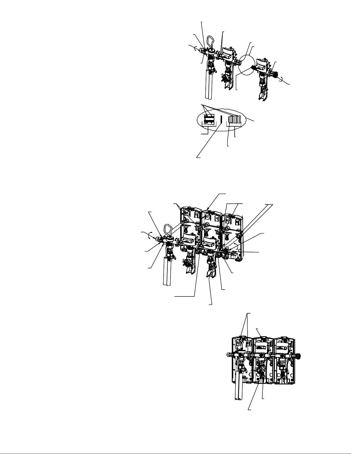
See section labeled “Maintaining and Servicing the DAH Blend Center” on page 9 for more information.
Trouble Probable Cause Remedy
Proportioner fails to draw
chemical properly. 1. Insufficient water supply pressure.
2. Inspect foot valve for dried chemical or dirt.
3. Proportioner metering tip clogged with dried
chemical.
4. Inspect Air Gap proportioner for mineral
deposit build up on top nozzle or inlet screen.
1. 20 PSI is the minimum allowable pressure. Seek
Plumber if necessary to increase water pressure.
2. * Soak in hot water to clean.
3. * Soak in hot water to clean interior passages.
4. * Soak nozzle and inlet screen in hot water or off
the shelf product such as CLR to clean and remove
mineral deposits.
“Air Gap” Proportioner is
dripping or spraying a mist
(fan pattern) of water.
1. Inspect “Air Gap” proportioner for mineral
deposit build up on top nozzle or inlet screen. 1. * Soak nozzle and inlet screen in hot water or off
the shelf product such as CLR to clean and remove
mineral deposits.
Sliding Lift Button won’t
“Lock” open for
continuous flow of
chemical/water solution.
1. “Sliding lift button” return spring may be
missing. (Note: Lift button must be slid up
before it will push in.)
2. Not using the proper procedure for locking the
water valve open.
1. Shut water supply off first. Slide “lever” all the
way up and hold it in place. Now push the button
in towards the wall. Let go of button and spring
should return lift button out to its original position.
Replace if missing.
2. See step 1 in section labeled “Getting to Know
Your DAH Blend Center” on page 2.
Water valve is not shutting
off completely. 1. “Sliding lever” return spring may be missing.
2. “Sliding lever” is not returning all the way
down due to interference between the sliding
lever and either the chemical supply and/or
outlet tubing.
3. Bucket fill outlet hose is catching the bottom
edge of the sliding lever during normal usage.
1. Remove cover and visually check for sliding lever
return spring. Replace if missing.
2. Remove cover and visually check for any tubes
rubbing the sliding lever. Routing of chemical
supply and outlet tubing must not restrict the
movement of the sliding lever. Reroute tubing.
3. Don’t pull the bucket fill outlet hose too tight from
either side otherwise sliding lever may not return
properly.
Water valve is leaking. 1. Enclosing tube nut is too loose.
2. One or more of the valve o-ring connections
are out-of-position. Clearly identify each leak
prior to disassembly.
1. Shut water supply off first. Hand-tighten the
enclosing Hose nut. Do not overtighten w/tool.
2. “O-ring” seals may be pushed out of place or
missing when subassembling valve together. See
section labeled “Adding a DAH blend center to an
existing DAH blend center” on page 10-13 for
reassembling.
Threaded connections are
leaking water. 1. The connection between the blend center and
water supply line is too loose or rubber washer
is missing.
2. Backflow prevention devices and/or
proportioners are too loose.
1. Shut water supply off first. Carefully tighten the
female hose coupling on the blend center to the
inlet water supply line. Do not overtighten.
2. Tighten loose connection(s) with tools if
necessary. Do not overtighten if using tools.
Proportioner continues to
draw chemical after water
valve is closed.
1. Concentrated chemical is positioned higher
than the proportioner. 1. Move the concentrated chemical so it is lower
than the proportioner.
Can’t pull the Remote Fill
Hose Assembly off of the
proportioner.
1. Hose Clamp is not loose enough.
2. Both 1/8” I.D. tubes must be removed prior
to removing the double hose.
1. Loosen clamp more.
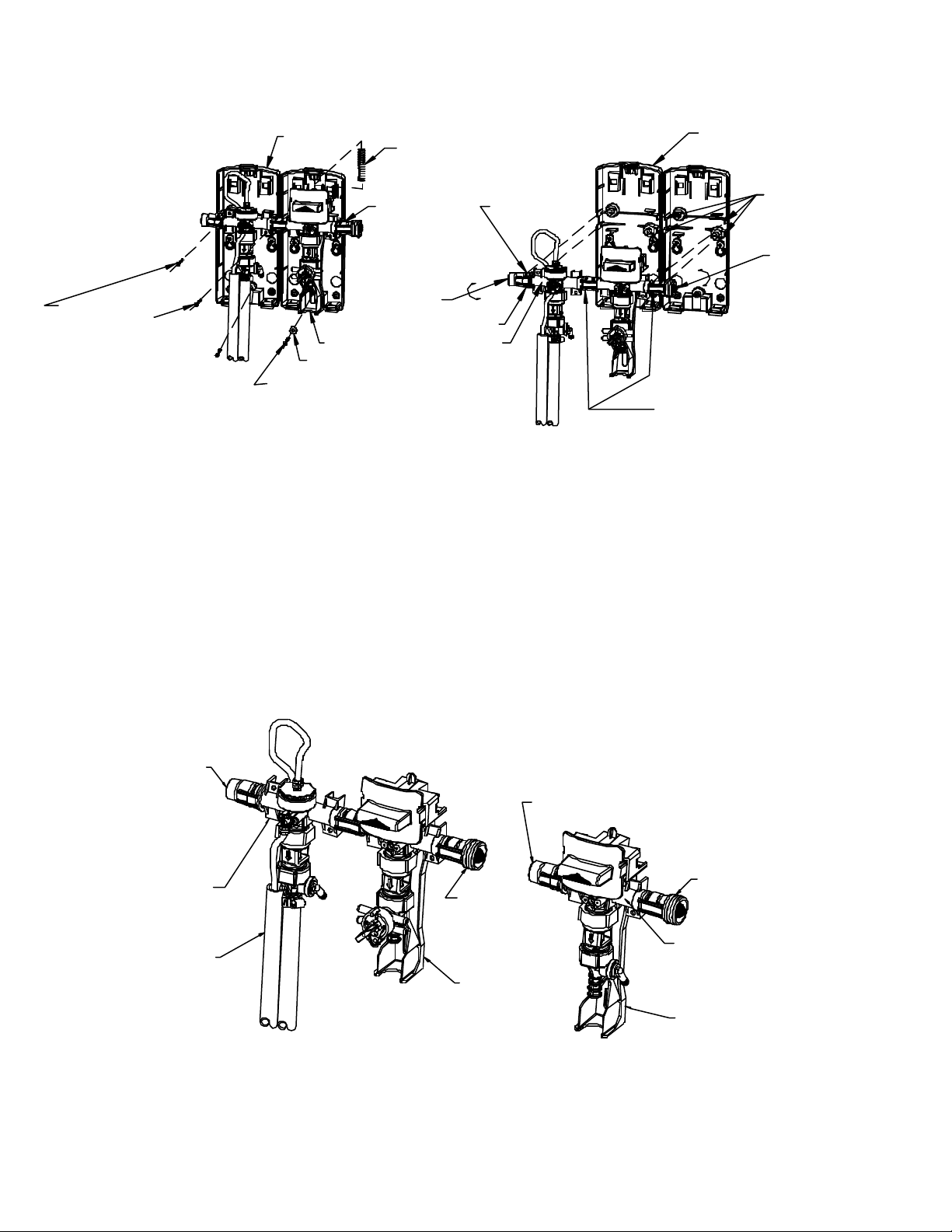
2. Remove 1/8” I.D. tubes. See section labeled
“Disassembling & reassembling the remote fill
hose assembly” on page 9.
Trigger on Remote Fill
Gun is very hard to
squeeze.
1. High pressure and low pressure (blue and
clear) hoses are crossed. 1. Install the blue and clear hoses according to
Figure 3 & 5 in the section labeled “Parts list for
DAH Blend Center” on page 15.
* (See section labeled “Checking backflow prevention device/proportioner, metering tip(s), and/or foot valve(s)” on page 10 for more information.)

I-776 Page 14of 18
Rev. G29208
Parts List For DAH Blend Center (Bottle/Hose Fill Applications)
(Some models may not include all items listed below)
(Always order by part number)
1
34
2
4
5
56
7
8
9
5FIGURE 1
SEE FIGURE 7
SEE FIGURE 6
SEE FIGURE 2
11
619-15 O-Ring (2 Req'd)
98-9-1 Cap
98-10-1 Water Inlet Stem
65-10 Hose Coupling, US
100-38 Strainer Washer
44-116-1 #8 Hi Lo Screw X 1/2" Lg. (3 Req'd)
98-21-1 Compression Spring (Lever)
98-4-1 Base
3
7
8
9
11
5
6
1
2
10
4
98-40-1 #10 Screw & Anchor Set (QTY 2 Each/Set)
98-20-1 Nylon Washer
619-15 O-Ring (1 Req'd Between Each Valve Body)
1
2
798-8-1
98-20-1
41-15-5
98-24-1
44-116-1
98-11-1
10
9
8
41-7-25
98-7-2
63-35
98-41-1
5
6
3
4
Enclosing Tube Nut
Lever (Valve Actuator)
#8 Hi Lo Screw X 1/2" Lg.
Plunger
Valve Body for Bottle/Hose Fill
Washer, Nylon
Diaphragm w/ center hole (EPDM)
Magnet
Enclosing Tube
Spring
10
98-55-1 Hose Coupling, Euro
11 98-25-1 Bottle/Hose Fill Repair Kit
5
NOTE: No Thru Hole
7
6
2
4
3
1
11
8
9
FIGURE 2
10

I-776 Page 15of 18
Rev. G29208
Parts List For DAH Blend Center (Remote Fill Hose Assembly Application)
(Some models may not include all items listed below)
(Always order by part number)
1
7
SEE FIGURE 6
SEE FIGURE 7
FIGURE 3
23
3
4
56
(SEE FIGURE 5)
High Pressure Tube
(Blue)
8
8
(SEE FIGURE 5)
Low Pressure Tube
(Clear)
98-30-1
98-31-1
FIGURE 5: REMOTE FILL HOSE ASSEMBLY
High Pressure Tube (Blue)
Low Pressure Tube (Clear)
Remote Gun Fill Half (R.H.)
Remote Gun Fill Half (L.H.)
3
High Press. (Blue Hose)
Low Press. (Clear Hose)
1
2
9
SEE FIGURE 4 FIGURE 5
SEE FIGURE 5
619-15 O-Ring (2 Req'd)
98-9-1 Cap
65-10
98-4-1 Base
3
1
2
FIGURE 4
1
2
58-60
98-15-1
98-11-2
98-26-1
98-5-2
26-35
5
6
3
4
Diaphragm W/O center hole (EPDM)
Elbow
#6 Hi-Lo Screw X 1/2" Lg. (2 Req'd)
Nut, Diaphragm
Valve Body for Remote Fill
O-ring
1
2
3
4
5
6
(SEE FIGURE 3)
For Connecting
Hose & Tubes
10
11
NOTE: Thru Hole
98-40-111
5
8
9
10
6
7
98-10-1
619-15
98-12-1
76-2-15
44-116-1
100-38
O-Ring (1 Req'd Between Each Valve Body)
#10 Screw & Anchor Set (QTY 2 Each/Set)
#8 Hi Lo Screw X 1/2" Lg. (2 Req'd)
Hose Clamp (2 Req'd)
Strainer Washer
Water Inlet Stem
Hose Clamp
498-55-1 Hose Coupling-U.S.
Hose Coupling-Euro. 98-57-1 Hose Assembly
Remote Fill Assembly
Hose Clamp (2 Req'd)
#6 Hi-Lo Screw x 3/4" Lg.
Valve Assembly
#6 Hi-Lo Screw x 1/2" Lg.
98-50
98-38
58-60
58-102
98-37-1
4
5
6
7
8
3
6
7
8
5
4
1
2

I-776 Page 16of 18
Rev. G29208
Parts List For DAH Blend Center
(Some models may not include all items listed below)
Always order by part number)
1
4
3
2
1 GPM Proportioner "Action Gap"
1
6
7
4
31
1
2
5
6
8
7
9
10
5
4 GPM Proportioner
4 GPM Proportioner
1 GPM Proportioner
9
8
10
Large end
of tapered
spring
* SECTION "A-A"
11 12
Long
Hose
1
1
3
2
4
5
6
Cutoff corner rib
2 places as shown
98-6-1B (See Figure 13 on page 17)
*
1
2Rubber Washer150-6
61-36 Flow Disk
3
461-99GAP-3
61-22GAP-3 Proportioner Assembly (1 GPM)
Proportioner Assembly (4 GPM)
5
87-4-1
16-30
87-6-1
87-5-1
87-3-1
150-6-11
9
10
11
6
8
7
Rubber Washer
Action Gap Assembly
Diaphragm
Spring
Nozzle
Retainer
98-42-2 Hose, 1/2" I.D. Outlet
Hose, 1/2" I.D. Outlet (6 Ft. Lg.)98-46-312
1100-59 StrainerWasher
Proportioner Assembly (4 GPM)
Nozzle
Nozzle
Screen3
4
5
263-77
61-126-AG-4
63-73
63-74-2
63-766
7
61-32AGP
Screen
Proportioner Assembly (1 GPM)
9
863-82
98-43-1 Hose, 3/16" I.D. Outlet
Hose, 9/16" I.D. Outlet
10 98-47-1 Hose, 9/16" I.D. Outlet (6 Ft Lg)
100-15K
100-12E
100-12 Metering Tip Kit (14 Sizes)
Hose, 1/4" I.D. x 8 Ft. Length
63-78 O-Ring
Elbow, 1/4
63-79
Hose, 1/4" I.D. x 50 Ft. Length
61-107-2
100-16E Ceramic Weight 3/8" I.D.
Foot Valve Assembly
116-4-3 Outlet Bucket Fill Hose Hanger
Long
Hose
2
6
4
5
3
1

I-776 Page 17of 18
Rev. G29208
Parts List For DAH Blend Center
(Some models may not include all items listed below)
(Always order by part number)
4
678
9
12
13
13
11
3
10
2
1
5
14
15
16
17
12
3
SEE FIGURE 11
(NOTE: Selector must be installed
into proportioner prior to installing
"Multi-Dilution Tubing")
PLAIN
COVER LIFT BUTTON
COVER
SELECTOR
COVER LIFT BUTTON &
SELECTOR COVER
14
7
9
83
6
SEE FIGURE 8
6SEE FIGURE 11
5
10
55 5
1111
7
2
10
89
4
1111
63-96-3
25-77
58-60
63-104
63-78
100-15K
63-98
66-13
63-51
63-101-2
63-100
6
12
13
14
9
10
11
8
7
3
4
5
2
1
SelectorBody
SelectorAssembly
Washer
Metering Tip Kit (14 Sizes)
O-Ring
Nut
Screw, RD Head
Seal Ring
Retainer
O-Ring (4 Req'd)
Knob
66-40 O-Ring
58-60 #6 HI-LO Screw
SelectorKnob63-111-2
17
16 100-16E
61-107-2
100-12E
100-12 Tube, 1/4 I.D. 8 Ft. Length
Ceramic Weight 3/8" I.D.
Foot Valve Assembly
Tube, 1/4 I.D. 50 Ft. Length
98-45-13
2
1
Tube, 7" Long (2 Req'd)
98-44-1 Tube, 2 3/8 " Long (2 Req'd)
BarbFitting100-60
4L835 Multi-Dilution Label (Shown)
63-36
98-3-2 58-60
63-111-2
98-3-4
8
7#6 Hi-Lo Screw
Cover w/Selector
Cover w/Lift Button & Selector
Spring, Lift Button Return
SelectorKnob
98-3-1 PlainCover
Cover w/Lift Button
98-3-3
11
9
L827 Blank Selector Label (Shown)L828
L829 ChemicalLabel
L835 Multi-Dilution Label (See Figure 12)
15
4
3
2
1
698-6-1B Lift Button
5Label, Bottle & Hose Fill
L856 Label, Remote Fill
10

I-776 Page 18of 18
Rev. G29208
Parts List for DAH Rack Assemblies
(Some models may not include all items listed below)
(Always order by part number)
5
SINGLE UNIT
SEE FIGURE 1 OR 3
10
DUALUNIT
SEE FIGURE 1 or 3
7
3
4 Places
11
9
4
2
8
6
SINGLE UNIT
SEE FIGURE 1 or 3
2
4
1 5 4
DUAL UNIT
SEE FIGURE 1 OR 3
4
3
Cabinet Lock w/Key
#10 Screw, Washer & Nut Kit (Qty. 4 Each/Set)
#12 Screw & Anchor Kit (Qty. 4 Each/Set)
#10 Shakeproof Nut
Multiproduct Rack
Multiproduct Gate
Multiproduct Rack/ 1 Drip Tray Kit
498-103-1
98-104-1
66-127
66-21K
98-113-1
81-67-2
44-124-3
98-90-1
8
10
11
9
6
7
5
Drip Tray
Key Only
#10 Screw
Plate
98-107-1
98-106-1
66-213
1
2
1
GatePositionfor
Installing to Rack
Align gate
to Rack Gate
Single Product Rack
#12 Screw & Anchor Kit (Qty. 4 Each/Set)
#10 Screw, Washer & Nut Kit (Qty. 4 Each/Set)
Single Product Rack/Drip Tray Kit
Plate, DAH Mounting
8 Places
6
5
6
4
3
2
1
98-103-1
98-112-1
98-90-1
98-105-1
98-104-1
66-127
Drip Tray
Rack
Table of contents
Other DEMA Laboratory Equipment manuals

DEMA
DEMA 292QD AERATING WAND User manual

DEMA
DEMA 633GAP Series User manual

DEMA
DEMA Fusion One Assembly instructions

DEMA
DEMA 163-2DF-2 User manual

DEMA
DEMA 163CH User manual

DEMA
DEMA 94235 User manual

DEMA
DEMA 203BS-2EP User manual

DEMA
DEMA 681GAP-2P User manual

DEMA
DEMA 633AG-1 User manual

DEMA
DEMA 162HCGHT User manual
Popular Laboratory Equipment manuals by other brands

Andor Technology
Andor Technology Mechelle user guide

Optika Italy
Optika Italy ACCESSORIES Series instruction manual

Pall
Pall Minimate EVO TFF quick start guide

VERDER
VERDER Carbolite Gero PN 120 Installation, operation and maintenance instructions

Sarstedt
Sarstedt SMC 6 V instruction manual

TA Instruments
TA Instruments DHR Series Getting started guide