Denios Bio.x B200 User manual

Cleaning Table
USERS MANUAL 10/2008
175733_BA_EN_004

bio.x B200 Page 2 of 12 10/2008
172236, 172292, 176074
Inhaltsverzeichnis
1. General Instructions..................................................................................................... 2
2. Safety instructions ....................................................................................................... 3
3. Technical data............................................................................................................... 3
4. Product description...................................................................................................... 4
4.1 Layout ............................................................................................................................ 4
4.2 Intended use .................................................................................................................. 5
4.3 How it works................................................................................................................... 5
5. Initial Operation ............................................................................................................ 5
5.1 Electrical connection ...................................................................................................... 5
5.2 Filling with the cleaning fluid .......................................................................................... 5
6. Operation.......................................................................................................................6
7. Maintenance.................................................................................................................. 6
8. Optional Accessories................................................................................................... 7
9. Notes regarding disposal............................................................................................. 8
10. Faults............................................................................................................................. 8
11. Connection Diagram................................................................................................... 10
12. EC Declaration of Conformity.................................................................................... 11
1. General Instructions
This user manual is for the bio.x parts cleaning unit B200. It contains all the information needed regarding
correct startup, trouble-free operation, maintenance, removal from service and disposal. The information
and instructions in this user manual have to be observed and adhered to.
If the instructions are strictly followed in accordance with the user manual, we accept liability within the
scope of our conditions for guarantees.
Without approval from the manufacturer no changes, extensions or modifications may be made to the
product. For changes made without approval from the manufacturer no liability is assumed and the
guarantee expires.
National regulations and safety regulations have to be adhered to.

bio.x B200 Page 3 of 12 10/2008
172236, 172292, 176074
2. Safety instructions
This unit can only be used safely if you read this user manual carefully and strictly follow the instruc-
tions it contains. This user manual is an integral part of this unit and must be available to the person-
nel who operate the unit at all times.
Such staff must be familiarised with the user manual with particular attention being paid to prohibitions
and hazard warnings.
The mains supply connection has to be in accordance with the corresponding regulations (VDE 01000 -
Association of German Electricians). For safety reasons the equipment must be only operated, if a Resid-
ual Current protective Device (RCD) with a release current of 30 mA is connected upstream.
This must be checked by a qualified electrician.
In accordance with the German BGV A3 electrical equipment has to be examined in regular inter-
vals.
The equipment must be set up on a suitable stable, level surface.
Detergents which contain highly flammable substances must not be used. Use only detergents ap-
proved by DENIOS for this unit.
3. Technical data
Dimensions 890 x 750 x 1155 mm
Net weight 45 kg
Power consumption max. 660 W
Electrical connection 1/N/PE 230V∼, protection category 1
Pre-fusing 10 A
Work surface height 950 mm
Load capacity 100 kg
Tank LDPE
Maximum fill capacity approx. 90 l
Minimum fill capacity 40 l
Usable work surface 760 x 560 mm
Heater Throughflow heater consumption 600 W
Level switch Minimum fill level (approx. 40 l)
Operating temperature Set at 41°C in the factory
Pump, flow rate 4l/min

bio.x B200 Page 4 of 12 10/2008
172236, 172292, 176074
1
2
3
4
5
6
6.1
6.2
7
8.1
8
9.2
9.18.2
8.3
8.4
8.5
9
4. Product description
4.1 Layout
Item Description Mat.
No. Item Description Mat. No.
A ON-OFF switch - 7 Draining device set 175373
B Display level - 8 Technical components set 175340
1 Sump -
8.1 Throughflow heater 174944
2 Stand top - 8.2 Pump 134979
3 Stand top seal 175033 8.3 Aerator 135310
4 600 µm filter screen 135256 8.4 Level switch 174951
5 Coarse filter 135255 8.5
Non-return valve 174959
6 Cleaning unit set 175370 9 Filter set (optional) 172237
6.1
Ball valve 135279
9.1
Filter insert
(central support bracket and
nylon filter)
150043
6.2 Wash brush 135277 9.2 O-ring 150609
A
B
bio.x B200 Page 5 of 12 10/2008
172236, 172292, 176074
4.2 Intended use
The bio.x parts cleaning unit is used to clean oil and grease from work pieces in an efficient, environmen-
tally sustainable way using exclusively cleaning fluids authorised by DENIOS.
Other detergents such as degreasers or alkali cleaning agents must not be used!
Solvents, disinfectants, alkali or acidic fluids, carburettor and diesel fuels or turpentine must not be
poured into the appliance.
4.3 How it works
A pump feeds the cleaning fluid through the throughflow heater to the three-way stopcock and the cleaning
brush. In warming-up mode the cleaning fluid returns to the tank via a bypass pipe with a non-return value.
An air pump ensures a good supply of oxygen for the cleaning fluid.
The pump and aerator run continuously.
The throughflow heating is controlled via an integrated sensor.
The pump, air pump and throughflow heater are switched on/off via a 230 V mains switch (A).
5. Initial Operation
After removing the packaging, check the unit casing and operating components for any possible damage
caused in transit. If such damage is found, do not connect the unit to the mains. Report damage immediately
to the carrier who delivered the unit and to DENIOS AG at the service number indicated above. The original
packaging should be kept.
Place the unit in a dry, stable location as required.
The floor must be level. If necessary, level out any uneven surfaces with suitable shimming material.
5.1 Electrical connection
The unit is connected to the customer's mains supply via the power cable and plug.
Mains voltage: The voltage of the power source has to comply with the details on the identification place of
the appliance
Warning: The mains supply must be fitted with a residual current protective device in accordance with
DIN VDE (Association of German Electricians) 0100! (See section 2)
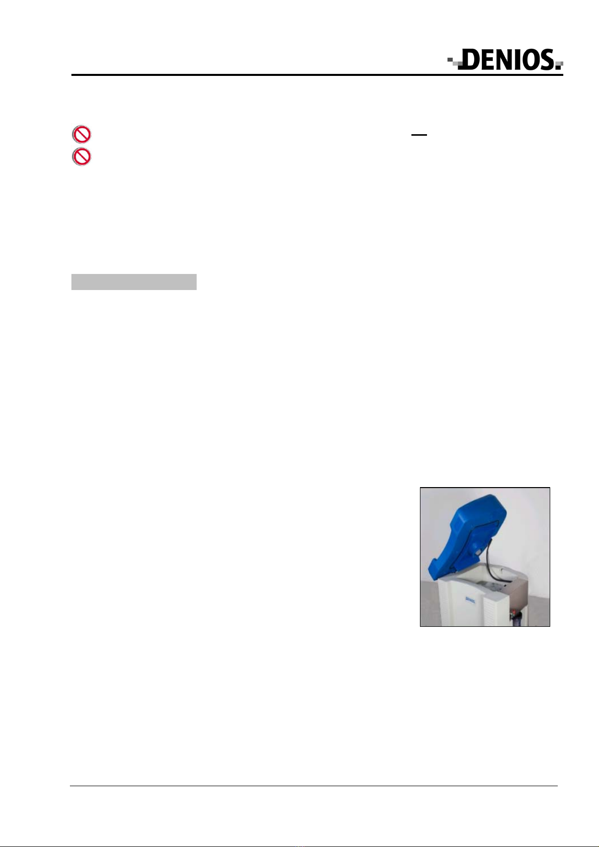
5.2 Filling with the cleaning fluid
The unit can be opened at the side for servicing or to fill the tank with fresh
detergent. To do so, lift up the right-hand side of the unit top and prop it up
using the bar you can find inside.
Two different cleaning fluids can be used in the Part Cleaning Unit B200.
a) Bio-Power cleaning fluid
•Pour 80 l (4 canisters) of Bio-Power cleaning fluid into the tank.
•Connect the unit to the mains. Turn on the appliance with the ON-OFF
switch. The pump, heater and aerator are turned on. The warming-up
process can take up to 5 hours, depending on the initial temperature.
The operating temperature is set at 41º C in the factory and cannot be
changed.
•You can measure the current temperature of the cleaning fluid with a
standard thermometer.
•Once the operating temperature is reached add the additive with the
micro-organisms (1 can x 100 g) to the fluid. The micro-organisms take
24 hours to become active.
The parts cleaning unit is then ready for operation.
Maintenance position of
stand top (aperture angle
a
pp
rox. 50°
)
Other manuals for Bio.x B200
1
Table of contents
Other Denios Ultrasonic Jewelry Cleaner manuals


