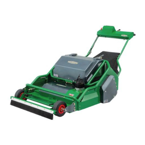
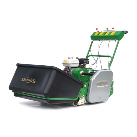
Dennis PRO 34R User manual

PRO 34R
INSTRUCTION MANUAL

Product Application Matrix
NOTE:-THIS INFORMATION IS INTENDED FOR GUIDANCE PURPOSES ONLY. WE RECOMMEND THAT YOU DICUSS YOUR
SPECIFIC REQUIREMENTS WITH OUR HEAD OFFICE, SALES MANAGERS OR YOUR LOCAL DENNIS DEALER
1

2
CERTIFICATE OF CONFORMITY
PRO 34R Rotary mowers powered by Honda GX Petrol Engine
Manufacturer:-Howardson Ltd, Howardson Works, Kirk Langley, Derby, DE6 4NJ. UK
Owner of Technical Document:-Mr I.D. Howard, Howardson Ltd, Howardson Works Kirk Langley, Derby, DE6 4NJ, UK
I the under signed Declare that these machines:-
The reliability and quality of performance of the DENNIS PRO 34R depends upon some simple care maintenance
carried out regularly. This manual has been prepared to allow the user to carry out all such work.
It is advisable to read the instructions carefully. Proper care and attention will enable the machine to give a continuous,
satisfactory, and reliable service. Failure to carry out regular lubrication and maintenance as outlined in this manual may
render any guarantee or warranty invalid.
In the case of any difficulty, or if further information or advice is required, our Service Department is always at your call. In
the interests of speed and accuracy of informationplease quote the serial numbers of the machine and engine when
making enquiries.
For the machine, this is to be found on a plate attached to the side frame. The engine number is stamped
on either the crank case or the gear casing facing towards the front of the machine. We suggest you write
the numbers on the front page of this book.
INTRODUCTION
SERIAL NUMBERS
Tested at:- Howardson Works test site October 2017
Complies with the applicable requirements of:-
-Machine Directive 2006/42/EC
-Noise Directive 2000/14/EC (Annex VI Procedure 1)
Ian Howard
Managing Director
NOTE:-MAKE A NOTE OF THE SERIAL NUMBER OF YOUR MACHINE AND ALWAYS
QUOTE IT IN ANY COMMUNICATION WITH PERSONNEL AT DENNIS.
MACHINE SERIAL NUMBER
ENGINE SERIAL NUMBER
Model Cutting
Width Power (Honda) Measured Sound Power
Level Guaranteed Sound
Power Level Serial Number
PRO
34R 34” (86cm) GX200
(4.1kW @ 3600 rpm) 99dB Lwa 100dB Lwa See product ID Range

3
CONTENTS
TECHNICAL DATA
Page
Product Application Matrix……………………….………...…………………………………………………………………………..1
Declaration of Conformity...................................................................................................................................................... 2
Serial Numbers...................................................................................................................................................................... 2
Introduction............................................................................................................................................................................ 2
Technical Data....................................................................................................................................................................... 3
Machine Description…………………………………………………………………………………………………………………….4
Important Safety Instructions................................................................................................................................................. 5
Controls……….……………………...……..…………………………………………………………………………………………...6
Operating Instructions....................................................................................................................................................... 7 - 8
Adjustments…….………………………………………………………………………………………………………………..…9 - 10
Routine Maintenance and Lubrication………….….…………..……………………………………………………………………11
General Lubrication……………………………..………….…………………………………………………………………………12
Storage………………………………………………………………………………………………………………….......................12
Parts Listings............................................................................................................................................................. P0 – P12
MODEL PRO 34R
A –WIDTH (cm)108.4
B –LENGTH (cm)189.5
C – Height (cm)108
Weight (Kg) 190
Cutting Width (cm)86
Number of Rotary Blades 2
Height of Cut (mm) 15 -50
Engine Honda GX200
Measured Sound Power Level 99 dB Lwa
Guaranteed Sound Power Level 100 dB Lwa
Vibration (m/sec^2) 4
MAX RPM (Under Load) 2800 min-1

4
Machine Description
NUMBER PART NUMBER PART
1Rotary Blades 9Grass Box
2Tilt Adjuster 10 Cutting Height Adjustment
3Belt Guard 11 Blade Control
4Throttle Control Lever 12 Gear Control Lever
5Operating Console 13 Air Filter
6Exhaust 14 Height Gauge
7Fuel Tank 15 Deadman's Handle
8Driving/Brake Control Lever 16 On/Off Switch
12
3
4
5
6
7
8
9
10
11
12
13
14
15
16

5
Important Safety Instructions
In order to operate the machine safely please follow these Health and Safety guidelines
Where possible, steps have been taken during the design of this machinery to reduce noise emission***.
To take full advantage of this, it is essential that the machine only be used when setup correctly and is fully serviceable
(see instructions).
***Note: Mandatory Ear Protection required when Sound Pressure Levels reach 85 dB LPA.
TRAINING
CAUTION –READ THE INSTRUCTIONS CONTAINED IN THIS MANUAL WITH CARE. IF YOU ARE IN
ANY DOUBT PLEASE ASK YOUR EMPLOYER OR CONTACT US DIRECT AT DENNIS
•Be familiar with the controls and the proper use of the equipment.
•Never allow children or people unfamiliar with these instructions to use the mower. Local regulations or insurance may
restrict the age of the operator.
•Never mow while people, especially children, or pets are near by.
•Keep in mind that the operator or user is responsible for accidents or hazards occurring to the other people or their property.
PREPARATION
•While mowing always wear substantial footwear and long trousers. Do not operate the mower barefoot or in open sandals.
•Thoroughly inspect where the equipment is to be used and remove all stones, sticks, wire, bones and other foreign objects.
WARNING –PETROL IS HIGHLY FLAMMABLE AND WILL DAMAGE GRASS IF SPILT.
A. Store fuel in containers specifically designed for this purpose.
B. Refuel out doors and do not refuel whilst smoking.
C. Add fuel before starting the engine. Never remove the cap of the fuel tank or petrol while the engine is running or when the
engine is hot.
D. If petrol is spilt do not attempt to start the engine but move the machine away from the area of spill and avoid creating and
sources of ignition until the vapours have dissipated.
•Replace damaged or faulty silencers.
•Before using the machine always inspect the safety devices including the cut off switch and the blades for excessive wear or
damage. Replace if necessary.
OPERATION
•Do not operate the machine when tired, ill, under the influenceof drugs or alcohol.
•Do not operate the engine in a confined space where dangerous CARBON MONOXIDE fumes can collect.
•Mow only in daylight or good artificial light.
•Do not operate the machine when there is risk of lightening.
•Avoid operating the machine in wet grass where feasible.
•Always be sure of your footing on slopes.
•Do not mow excessively steep slopes.
•Walk across the face of slopes, never up and down.
•Exercise extreme care on slopes when changing direction.
•Walk. Never run.
•Use extreme caution when reversing or pulling the machine towards you.
•Stop the blades if the mower has to be tilted for transportation when crossing surfaces other than grass and when
transporting the mower to and from the area to be mown.
•Never operate the mower with defective guards or shields or without safety devices, for example without the deflector plate
or grassbox in place.
•Do not change the engine governor settings or over speed the engine.
•Disengage all blades and drive clutches before starting.
•Start the engine carefully following the instructions with feet well away from the blades.
•Do not tilt the mower when starting the engine.
•Do not put hands or feet near the under rotating parts. Keep clear of the discharge opening at all times.
•Never pick up or carry the mower while the engine is running.
6
Controls
FOR THE LOCATION OF CONTROLS AND COMPONENTS REF “MACHINE DESCRIPTION” PAGE.
ON / OFF SWITCH (ITEM 16)
This switch stops the engine and can be used to do so at anytime during the operation of the machine. Ensure it is in the “ON”
position before attempting to start the engine.
DEADMANS CONTROL (ITEM 15)
This is an operator presence control. The engine will tick over without need for this to be depressed when the cutter and drive
are disengaged. This must be depressed before the drive or cutter can be engaged. Failure to do so will cause the engine to
stop.
THROTTLE CONTROL (ITEM 4)
This controls the RPM of the engine and in conjunction with the selected gear, controls the resultant speed of the machine.
Pulling back will increase the RPM, pushing it forwards returns the engine to idle.
The maximum engine speed for this machine is set to 2800Rpm when the blades are engaged.
DRIVE CONTROL/ BRAKE CONTROL (ITEM 8)
This controls the machines movement. Pushing the lever forwards will engage the Drive Clutch and Disengage the Brake,
causing the machine to move. Returning it to the original position will cause the machine to stop and the Brake to engage. Note:
Movement will only occur if a gear is selected, see Gear lever controls.
BLADE CONTROL (ITEM 11)
This controls the drive to the blades. Pulling the lever backwards will engage the clutch and cause the Blades to rotate.
Returning it to its original position will cause the Blades to stop.
GEAR CONTROL (ITEM 12)
The machine has 1-Reverse and 5-Forward gears, gear 1 being the slowest. The forward speed can be fine-tuned using the
Throttle Control.
HEIGHT OF CUT CONTROL (ITEM 10).
The length of grass after cutting depends on the position of the wheels in relation to
the rear roller.
Setting the Height of Cut is done using the knob (item 10). (see fig 1)
Rotating this Anticlockwise will reduce the length of grass and Clockwise will increase
the length of grass. Each click of the control will result in a height change of
approximately 0.5mm
When using the Height Gauge (item 14) as shown in fig 1.1, the cut height can be
set accurately.
The Height Gauge is stored on the right hand side of the engine (see fig 1)
The Gauge must be removed from the deck before commencing mowing.
After a significant height change (More than 3mm -4mm) the Deck Angle may need
adjusting.
NOTE: Ground conditions can affect the finished Height of Cut. If the ground is soft,
the machine will sit lower and result in a lower cut height.
DECK TILT CONTROL (ITEM 2)
To achieve the best possible cut and collection the Tilt angle of the deck can be
adjusted. This is achieved using item 2, fig 1
Tilt ON lifts the back of the Deck, Tilt OFF lowers the back of the Deck. Each click
of the control will result in an angle change of approximately 0.1 degrees.
The back of the deck should always be higher than the front (Tilt ON). For normal
conditions we recommend an angle of 1 to 1.5 degree.
Setting the angle is simple. For 1 to 1.5 degrees of Tilt ,the back of the Deck should
be 8mm to 12mm higher than the front.
Alternatively, a digital level can be used to set the Deck angle.
FRONT BRUSH
This is designed to agitate any lose material in front of the mower to aid collection.
This can be set using the adjusters in figure 1.2
Height Gauge
Figure 1.1
Figure 1
Item 2
Item 10
Height Gauge
Figure 1.2
Adjusters

7
OPERATING INSTRUCTIONS
CAUTION –BEFORE YOU OPERATE THIS MACHINE YOU MUST READ AND STUDY THIS MANUAL IF
YOU ARE IN ANY DOUBT PLEASE ASK YOUR EMPLOYER OR CONTACT US DIRECT.
PREPARATION FOR USE
•Before commencing ensure the turf is free from stones and other obstructions which may damage the cassette unit.
•Set the height of the cut to the required level. (see general adjustments)
•Check the engine
•Fill the fuel tank 3/4 full with unleaded petrol.
•Always check the oil levels of the machine prior to commencing. Full details are given in the ENGINE manual, which
accompanies this book. A daily check is recommended. (Recommended grade oil is SAE 10W-40).
•Disengage the cassette unit. (see general adjustments)
•Set the throttle control on the handle to the idle position.
CAUTION –IMPORTANT INFORMATION PLEASE READ ALL THE DETAILS IN THIS SECTION AND
FAMILIARISE YOURSELF AND ALL MACHINE OPERATORS WITH THE CONTENTS.
STARTING THE ENGINE
Once the preparatory steps have been completed as outlined on page 7 the engine may be started. (see manufacturer
operating manual for full details).
1. Switch on the fuel tap.
2. Switch the handlebar “off switch” to ON,
3. Set the throttle control to a half open position.
4. Shift the choke lever to the appropriate position . The choke is not required if the engine is warm or the air temperature is
high.
5. Grasp the recoil start handle until resistance is felt, then pull it with force.
6. Do not allow the starter grip to snap back against the engine. Return it gently to prevent damage to the starting position.
7. Once the engine is started, gradually ‘open’ the choke lever (move the lever towards the RUNNING, or OPEN position).
Warm-up running of 3-5 minutes is recommended.
STOPPING THE ENGINE
1. Set the throttle control to the CLOSED position.
2. Switch the handlebar cut off to OFF
3. Close the fuel tap.
TO COMMENCE DRIVING (TRANSPORT BETWEEN SITES / NO CUTTING)
.
•Depress the “Deadmans Handle” (Item 15)
•Push the “Drive Control Lever” (Item 8) forwards.
•Set the “Throttle Control Lever” to increase / reduce speed.
TO STOP DRIVING
•Pull the “Drive Control Lever” (Item 8) backwards. This will engage the brake.

8
OPERATING INSTRUCTIONS
TO COMMENCE CUTTING
•Depress the “Deadmans Handle” (Item 15)
•Pull the cutter control lever backwards.
•Push the “Drive Control Lever” (Item 8) forwards.
•Set the “Throttle Control Lever” to increase / reduce speed.
TO STOP CUTTING
•Pull the “Drive Control Lever” (Item 14) backwards.
•Push the cutter control lever forwards.
•Release the “Deadmans Handle” (item 15)
NOTE –Releasing the “Deadmans Control Lever” with the blades engaged will cause the engine to stop.
FITTING THE GRASSBAG (Item 9)
•Ensure cutter drive is disengaged
•Lift the Grassbag cover fig 2
•With the other hand, lift the Grassbag, tilting it back slightly.
•Remove the Grassbag up between the handle bars
•Empty the bag and replace.
Figure 2
Cover

WARNING -Shut off engine before commencing any maintenance, service or adjustments.
BRAKE
Engaging the Roller Drive, (Item 8) automatically disengages the Brake. The
Brake can be adjusted to ensure it is completely OFF when the Roller Drive
is engaged and ON when the Roller Drive is disengaged.
Fig 3 shows the Transmission and Disc Brake mounted beneath the Chassis.
The nut highlightedin the diagram is the adjuster for the Brake.
With the machine in Neutral, and the Brake engaged (Roller Drive disengaged),
adjust the nut until the machine cannot be pushed.
Disengage the Brake (engage the Roller Drive), check the machine can be pushed.
If the Brake is still engaged, adjust the nut to free it off.
Repeat the adjustment until the Brake is fully ON when the Roller Drive is
disengaged and OFF when the Roller Drive is engaged.
ROLLER DRIVE BELT
This connects the Top Gearbox to the Transmission fig 4. This Belt is
clutched when you operate the Roller Drive Lever.
This can be adjusted by moving the Top Gearbox on its slotted mountings.
Moving the Top Gearbox will require the position of the couplings to
be altered on the shafts.
Replacement
A new Roller Drive Belt can be fitted without removing any components
(After removing guards)
BLADE DRIVE
The Blade Drive system consists of a Clutch -Brake attached directly to
the engine (fig 5). This drives twin 90 degree Gearboxes mounted on the
Deck (fig 5) via a special high load “B” section Kevlar V Belt.
Clutch –Brake
There are 2 points of adjustment for the Clutch -Brake, both on the Cable
that connects the Clutch -Brake to the Lever (fig 6)
The Clutch -Brake is correctly adjusted when Spring (fig 6), has an
extension of between 23mm and 24mm.
When the Clutch -Brake is disengaged the blades should
stop with in 5 seconds. There should be no “Rubbing”
noise coming from the Clutch -Brake. When it is disengaged.
9
Adjustments
Figure 3
Figure 4
Figure 6
Figure 5
Clutch - Brake
90°Gearboxes

10
Adjustments
Cutter Drive Belt
This connects the Clutch –Brake to the Gearboxes on
the Deck. There are adjusters mounted on the side
plates that allow the deck to be moved forwards. (fig 7).
This will tension the Cutter Drive Belt.
The 4-off M10 Bolts each side (fig 7) need to be
slackened before any adjustment can be made.
Use the adjuster bolts (fig 7) to move the deck forward.
Note: It is important that equal adjustment is made on
the Left Hand and Right Hand side of the machine.
Sufficient tension is achieved when a 5mm deflection is
observed at mid span with a moderate finger pressure.
Belt Replacement
Replacing the Cutter Drive Belt is very simple. (Estimated time 30
minutes)
Remove the plastic plugs in the 90 degree gearboxes (fig 8)
Remove M10 blade retaining bolts [B] (17mm spanner) to remove
blades.
Unbolt the 4-off M10 Caphead bolts that hold the Gearboxes to the
deck.[A] (8mm Allen key, 17mm spanner). This allows the gearbox and
blade assembly to be raised up.
Thread the new Belt over the gearbox assembly.
Replace the Gearbox assembly.
Remove / slacken the bolts highlighted in fig 9.
Remove the Top Drive shaft.
Put the new belt over the Clutch Pulley. Note slacken off the belt
adjusters (see belt adjustment section)
Replace the Top Drive Shaft.
Replace / Tighten bolts in fig 9.
Adjust the Belt as described in “Belt adjustment section”.
Note: The tension of a new Belt should be checked after 30 minutes of
running.
An incorrectly adjusted belt will lead to premature wear.
4-off M10 Bolts
Figure 7
Adjuster Bolts
Figure 9
Figure 8
Bolts [A]
Plugs
Bolts [B]

11
Routine Maintenance and Lubrication
ENGINE
The machines are fitted with a GX200 petrol engine.
For full specifications please refer to the manufacturers instruction manual included.
Area Maintenance Each Use First Month / 20 Hours 6Months / 100 Hours
Engine Oil Check Level
Engine Oil Change
Air Filter Check Condition / clean
Spark Plug Change
OIL / FUEL & QUANTITY –SPARK PLUG TYPE
Engine Model Oil Types Quantity (Ltr) Fuel Type Capacity (Ltr) Spark Plug
Type Electrode
Gap (mm)
Gx200 Petrol SAE 10W-30 0.6 unleaded 3.1 BM6ES or
BPR6ES 0.7 –0.8
BLADES
Worn or damaged blades can be dangerous resulting in serious injury or death of the operator or bystanders.
Blades must be inspected weekly for wear or damage. This can be observed as impact (dents), material cracking and
excessive thinning.
Replace worn or damaged blades.
Note: Using non-genuine parts could result in non-compliance with safety standards and may invalidate your warranty.
For details of blades and Torque settings Ref. Section P2 of this manual.
CLEANING (After Each Use)
Deck
Tilt the machine backwards. Using a low pressure hose, wash all the grass from around the deck and in the chute.
NOTE: DO NOT use power pressure washers to clean the mower.
Grassbag
Washing with high pressure water or steam jet will damage the bag.
Blocked mesh will prevent the grass from entering the bag.
To clean the bag, we recommend washing it using a water jet directed from the outside to the inside of the bag. The bag must
be completely dry before being used again. If the bag is damp, it will become clogged very quickly.
Objects struck by the blade may be thrown through a torn or damaged grass bag.
Objects thrown out by the blade can cause serious injuries.
Always replace a torn or damaged bag.
Bag Replacement –The grass bag tends to wear even in normal conditions of use. Regularly check that it is not frayed or
torn. Replace a damaged bag only by a genuine Dennis replacement bag.

12
General Lubrication
REAR ROLLER CHAIN
(1-month)
Apply a small amount of grease.
WHEEL BEARINGS
(1-months)
Two grease points on the bolts that hold the wheel axle. Apply one pump of grease to each.
CONTROL LEVERS AND CABLES
(2-months)
Apply a small amount of oil to the control cables. Flow down the protective cables can be assisted by operating the lever a few
times after lubricating.
TILT CONTROL
(2-months)
Apply a small amount of grease through the grease nipple. .
HEIGHT OFCUT STAINLESS SHAFT
(6-months)
Apply a small amount of grease through the grease nipple. NOTE: To access this grease point you will need to remove the right
hand side guard.
90 DEGREE GEARBOX
(100-Hours)
Fill to halfway up the top shaft EP90.
Storage
The machine should always be kept in a clean dry place, free from condensation. After use ensure that the machine is
thoroughly clean, dry and free from grass and mud. Before off season storage smear a thin layer of grease on to the
cutter blades and the shear blade.
Under no circumstances must the machine be steam cleaned as this may remove grease from the pre packed bearings.
Because of the nature of lead free petrol we recommend that if the machine is being left unused for more than 2 weeks the
carburettor is run dry. Allow the engine to run out of fuel with the fuel tap switched off.

NOTES

PRO 34R - PARTS BOOK
P0

10
10
25 19 36
24 37 33
5 12
24 37 31
9
24 37 33 31
3
2738354
21292929
8
22
223033
3033
6
20
7
13
1
17
1
16
1
15
24
37
33
17
16
1
4
2
27 35 32
18
18
3911
24 37 33
26 34 28
8
P1.01
CHASSIS

ITEM NO.
PART NUMBER
DESCRIPTION
CHASSIS/QTY.
1
229005_REV2
CABLE STOP
2
2
320010_REV0
SIDE PLATE ASSY L.H.
1
3
320011_REV0
SIDE PLATE ASSY R.H.
1
4
320020_REV1
CHASSIS 34" W.A.
1
5
320048_REV0
DECK SEAL
1
6
320048_REV0
DECK SEAL
1
7
320056_REV0
RETAINING PLATE
1
8
320060_REV0
BRACKET GBOX MOUNT
1
9
320061_REV0
BRACKET ANGLE
2
10
320063_REV0
TIE BAR ASSY
1
11
320065_REV0
SCRAPER BRUSH REAR ROLLER
1
12
320066_REV0
SEAL CLAMP
2
13
320067_REV0
PLATE RIVNUT
2
14
320201_REV0
GUARD BRACKET
1
15
320202_REV0
BRACKET ANTI-ROTATION
1
16
320212_REV0
GUARD STUD 61
1
17
320213_REV0
GUARD STUD 96
1
18
320214_REV0
GUARD STUD 44
4
19
E1-1065_REV0
SPRING WASHER M12 SQUARE SECTION
2
20
F21712_REV1
BUSH NYLON 1208 10
4
21
SP01023_REV0
HEX SET SCREW M8 X 60
4
22
SP01027_REV0
HEX SET SCREW M8 X 40
2
23
SP01034_REV0
HEX SET SCREW M10 X 20
2
24
SP01009_REV0
HEX SET SCREW M8 X 20
26
25
SP01065_REV0
HEX SET SCREW M12 X 30
2
26
SP01074_REV0
HEX SET SCREW M5 X 12
7
27
SP01105_REV0
HEX SET SCREW M10 X 30
8
28
SP02002_REV0
NUT M5 NYLOC (T)
7
29
SP02005_REV0
NUT M8 STD
12
30
SP02006_REV0
NUT M8 NYLOC (T)
2
31
SP02044_REV0
RIVNUT HEX M8 (0.5-3.0) [NO HEAD]
32
32
SP02046_REV0
RIVNUT HEX M10 (1.0-3.5) [NO HEAD]
8
33
SP03008_REV0
WASHER M8 FORM A
27
34
SP03009_REV0
WASHER M5 FORM A
14
35
SP03011_REV0
WASHER M10 FORM A
8
36
SP03012_REV0
WASHER M12 FORM A
2
37
SP03029_REV0
WASHER M8 SPRING LOCK
24
38
SP03034_REV0
WASHER M10 SPRING LOCK
6
39
SP24007_REV0
BRUSH H SECTION 4MM
1
CHASSIS
P1.02

10
4
16
9
9
19
20
33
34
35
29 18
8
17
32
3
6
2722
8
7
11
31
25
25
5
23
1
11
28
22
30
30
13
13
30
12
12
14
26
26
9242
21 15
21 15
TORQUE TO 40Nm
DECK
P2.01

ITEM NO.
PART NUMBER
DESCRIPTION
DECK/QTY.
1
228062_REV1
3/4" TUBE BUNG (3132)
4
2
228074_REV1
D315163175 BELLEVILLE WASHER
1
3
229110_REV1
BEARING UCFC205-25
2
4
320030_REV1
DECK 34" W.A.
1
5
320087_REV0
SPACER BOSS
1
6
320088_REV0
DECK PIVOT BOSS
2
7
320143_REV0
COLLAR SHAFT DECK
1
8
320146_REV1
BLADE MOUNT BODY
2
9
800237_REV0
CLICK ADJUSTER ASSY ROTARY
1
10
800549_REV0
GEARBOX ROTARY L.H.
1
11
800550_REV0
GEARBOX ROTARY R.H.
1
12
BA1014_REV0
KEY 6 X 6 X 20 RD END
2
13
D8153_REV1
GRUB SCREW M8 X 10
5
14
E1-1065_REV0
SPRING WASHER M12 SQUARE SECTION
8
15
SP01061_REV0
CAP HEAD M10 X 80 FULL THREAD
4
16
SP01078_REV0
HEX SET SCREW M12 X 40
8
17
SP01081_REV0
CAP HEAD M5 X 12
4
18
SP01105_REV0
HEX SET SCREW M10 X 30
2
19
SP01152_REV0
ROD M12 X 150
1
20
SP01155_REV0
CAP HEAD M12 X 55
1
21
SP02008_REV0
NUT M10 NYLOC (T)
4
22
SP02010_REV0
NUT M12 NYLOC (T)
9
23
SP02014_REV0
NUT M12 LOCK (THIN)
1
24
SP02028_REV0
NUT M16 NYLOC (T)
1
25
SP02044_REV0
RIVNUT HEX M8 (0.5-3.0) [NO HEAD]
4
26
SP03011_REV0
WASHER M10 FORM A
4
27
SP03012_REV0
WASHER M12 FORM A
8
28
SP03017_REV0
WASHER M12 FORM C
1
29
SP03037_REV0
WASHER 10.5 X 40 X 5
2
30
SP10005_REV0
KEY 6 X 6 X 30 RD END
3
31
SP11054_REV0
PULLEY V SPB 125
1
32
SP14011_REV0
INSERT 50MM SQ. 1.0-3.0
2
33
SP14022_REV0
ROD END M12 FEMALE
1
34
SP22007A_REV0
BLADE ROTARY L.H.
1
35
SP22007B_REV0
BLADE ROTARY R.H.
1
DECK
P2.02

4
9
213
586
37
5
1
6 5
2
ITEM NO.
PART NUMBER
DESCRIPTION
REAR ROLLER/QTY.
1
062662_REV1
BEARING 6205-2RS 3
2
2
229104_REV1
LANDROLL BEARING HOUSING
2
3
229892_REV1
M16 L.H. BOLT
1
4
800236_REV0
REAR ROLLER
1
5
SP01009_REV0
HEX SET SCREW M8 X 20
6
6
SP03008_REV0
WASHER M8 FORM A
6
7
SP03021_REV0
WASHER M16 FORM C
1
8
SP03029_REV0
WASHER M8 SPRING LOCK
6
9
SP11061_REV0
CHAIN 08B (1/2" PITCH)
1
REAR ROLLER
P3.01
Table of contents
Other Dennis Lawn Mower manuals

Dennis
Dennis ES-30 User manual

Dennis
Dennis Razor Ultra 560 User manual

Dennis
Dennis Simplex User manual

Dennis
Dennis G680 User manual

Dennis
Dennis E-SERIES ES-860 User manual

Dennis
Dennis E Series User manual

Dennis
Dennis E-SERIES ES-36 User manual

Dennis
Dennis E-SERIES ES-34R User manual

Dennis
Dennis FT 430 User manual

Dennis
Dennis Premier 30" User manual