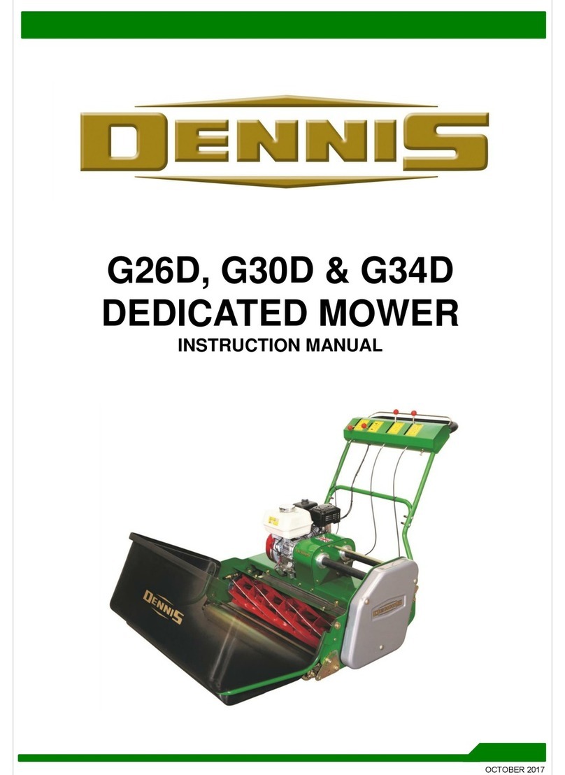
Dennis Simplex 510 User manual

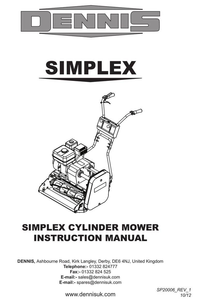
SIMPLEX
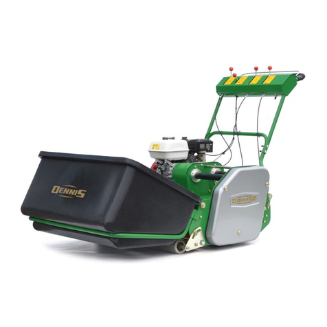
SIMPLEX CYLINDER MOWER
INSTRUCTION MANUAL
DENNIS, Ashbourne Road, Kirk Langley, Derby, DE6 4NJ, United Kingdom
Telephone:- 01332 824777
Fax:- 01332 824 525
E-mail:- [email protected]
www.dennisuk.com SP20006_REV_0
04/12

FT Razor Razor Simplex G560 SuperSix G660/G760 Premier ContractorBray Hand S500 Gang
Application Range 560
Ultra 560
Range G680 Range G860 Range Tools Plus Mower
Bowling Green 9999999
Cricket Ground Maintenance: wicket 999999
square 999999
RXW¿HOG 999
Football Pitch 999
Golf Course Maintenance: Tees 9999999
Greens 999999
Ornamental 99999
Croquet Green 99999999
Grass Tennis Court 9999999
Race Course Maintenance: Parade Ring 9999999
Ornamental 99999999
Rugby Pitch 999
Hockey Pitch 99
Sports Club Maintenance 999999999999
Schools, Colleges & University Grounds 999999999999
Cemetery Maintenance 9999
Contractors, Private Lawns & Commercial 9999999
Local Authority & Government Contracts 999999999999
Ornamental Lawn 99999999
THIS INFORMATION IS INTENDED FOR GUIDANCE PURPOSES ONLY. WE RECOMMEND THAT YOU DISCUSS YOUR SPECIFIC
REQUIREMENT WITH OUR HEAD OFFICE, SALES MANAGERS OR YOUR LOCAL DENNIS DEALER.
NOTE
Product Application Matrix

3
Simplex SP20006_REV_0
&HUWL¿FDWHRI&RQIRUPLW\
Simplex Cylinder mowers powered by Honda GX Petrol Engine
0DQXIDFWXUHU Howardson Ltd, Howardson Works, Kirk Langley, Derby, DE6 4NJ. UK
2ZQHURI7HFKQLFDO'RFXPHQW Mr I.D. Howard, Howardson Ltd, Howardson Works Kirk Langley, Derby, DE6 4NJ, UK
1RWL¿HG%RG\ AV Technology Ltd, AVTECH house, Arkle Avenue, Stanley Green Trading Estate, Handforth, Cheshire,
SK9 3RW, UK
I the under signed Declare that these machines:-
The reliability and quality of performance of the '(11,66,03/(; depends upon some simple care maintenance carried
out regularly. This manual has been prepared to allow the user to carry out all such work.
It is advisable to read the instructions carefully. Proper care and attention will enable the machine to give a continuous,
satisfactory, and reliable service. Failure to carry out regular lubrication and maintenance as outlined in this manual may
render any guarantee or warranty invalid.
,QWKHFDVHRIDQ\GLI¿FXOW\RULIIXUWKHULQIRUPDWLRQRUDGYLFHLVUHTXLUHGRXU6HUYLFH'HSDUWPHQWLVDOZD\VDW\RXUFDOO,Q
the interests of speed and accuracy of information please quote the serial numbers of the machine and engine when
making enquiries.
For the mower, this is to be found on a plate attached to the side frame. The engine number is stamped on either the
crank case or the gear casing facing towards the front of the machine. We suggest you write the numbers on the front
page of this book.
,QWURGXFWLRQ
Serial Numbers
0$&+,1(6(5,$/180%(5
MAKE A NOTE OF THE SERIAL NUMBERS OF YOUR MACHINE & ENGINE AND ALWAYS
QUOTE THEM IN ANY COMMUNICATION WITH PERSONNEL AT DENNIS.
NOTE
(1*,1(6(5,$/180%(5
Model Cutting Width Power (Honda) Measured Sound Power
Level Guaranteed Sound
Power Level Serial Number
510 20” (510mm) GX120 91dB Lwa 94dB Lwa See Product ID range
610 24” (610mm) GX120 91dB Lwa 94dB Lwa See Product ID range
7HVWHGDWHowardson Works test site September 2011
Complies with the applicable requirements of:-
- Machine Directive 2006/42/EC
- Noise Directive 2000/14/EC (Annex VI Procedure 1)
0DQDJLQJ'LUHFWRU
,DQ+RZDUG

4
Simplex SP20006_REV_0
Contents
Page
Product Application Matrix.................................................................................................................................................... 2
Declaration of Conformity.....................................................................................................................................................3
Serial Numbers..................................................................................................................................................................... 3
Introduction........................................................................................................................................................................... 3
Technical Data...................................................................................................................................................................... 4
Machine Description............................................................................................................................................................. 5
Important Safety Instructions................................................................................................................................................ 6
Controls................................................................................................................................................................................ 7
Operating Instructions .....................................................................................................................................................8 - 9
General Adjustments....................................................................................................................................................10 - 11
Routine Maintenance...................................................................................................................................................12 - 13
Storage............................................................................................................................................................................... 13
General Lubrication............................................................................................................................................................ 14
Notes.................................................................................................................................................................................. 15
Parts Listings...............................................................................................................................................................16 - 28
7HFKQLFDO'DWD
Model 510 610
A - Width (mm) 703 803
B - Length with Grassbox (mm) 7566 1566
C - Length without Grassbox (mm) 1203 1203
D - Height (mm) 983 983
Weight (Kg) 120 125
Cutting Width (mm) 510 610
Cylinder 5 or 7 blade 5 or 7 blade
Height of Cut (mm) 6 - 30 6 - 30
Cut Performance (5 Blade)
Cut Performance (7 Blade) 100 cuts/m (92 cuts/yd)
140 cuts/m (128 cuts/yd) 100 cuts/m (92 cuts/yd)
140 cuts/m (128 cuts/yd)
Engine Honda GX120 Honda GX120
Drive System “V” Belt “V” Belt
Final Drive Poly “V” high performance belts under
constant tension Poly “V” high performance belts under
constant tension
Hand Arm Vibration (m/sec2)1.9 1.9
Measured Sound Power Level dB(A) LWA 91 91
Guaranteed Sound Power Level dB(A) LWA 95 95
ABC
'

5
Simplex SP20006_REV_0
0DFKLQH'HVFULSWLRQ
Manufactured with a 20” (51cm), or 24” (61cm) cutting width, this range of machines is powered by a 4.0hp air cooled,
single cylinder, four stroke petrol engine.
The rear roller and cutter are controlled independently via belt clutches operated from the console on the upper handle
EDU,7(0$SDUNLQJEUDNHLV¿WWHGIRUDGGHGVDIHW\ZKHQZRUNLQJRQVORSLQJJURXQG
In the design of the machine, special attention has been given to the importance of easy service and maintenance with
the construction based on a sectional assembly system. These are the Engine Unit, the Cylinder, the Rear Roller Unit,
and the Front Roller Unit, each of which can be readily removed individually from the main Frame Chassis Unit.
The interchangeable cassette system allows a variety of cassettes to be used for varying applications.
1. Cylinder 9. Grassbox
2. Bottom Blade Adjuster Knob 10. Cutting Height Adjustment
3. Belt Guard 11. On / Off Switch
4. Throttle Control Lever 12. Cylinder Control Lever
5. Operating Console 13. Air Filter
6. Exhaust 14. Driving Control Lever
7. Fuel Tank 15. Deadmans Handle
8. Brake Lever 16. On / Off Switch
1
2
3
8
4
5
6
7
29
15
10
11 12
13
14

6
Simplex SP20006_REV_0
,PSRUWDQW6DIHW\,QVWUXFWLRQV
In order to operate the machine safely please follow these Health and Safety guidelines.
75$,1,1*
READ THE INSTRUCTIONS CONTAINED IN THIS MANUAL WITH CARE. IF YOU ARE IN
ANY DOUBT PLEASE ASK YOUR EMPLOYER OR CONTACT US DIRECT AT DENNIS.
&$87,21
Be familiar with the controls and the proper use of the equipment.
Never allow children or people unfamiliar with these instructions to use the mower. Local regulations or insurance may
restrict the age of the operator.
Never mow while people, especially children, or pets are nearby.
Keep in mind that the operator or user is responsible for accidents or hazards occurring to other people or their
property.
35(3$5$7,21
While mowing always wear substantial footwear and long trousers. Do not operate the mower barefoot or in open
sandals.
Thoroughly inspect where the equipment is to be used and remove all stones, sticks, wire, bones and other foreign objects.
PETROL IS HIGHLY FLAMMABLE AND WILL DAMAGE GRASS IF SPILT.
:$51,1*
$ 6WRUHIXHOLQFRQWDLQHUVVSHFL¿FDOO\GHVLJQHGIRUWKLVSXUSRVH
B) Refuel out doors and do not refuel whilst smoking.
C) Add fuel before starting the engine. Never remove the cap of the fuel tank or add petrol while the engine is running or
when the engine is hot.
D) If petrol is spilled do not attempt to start the engine but move the machine away from the area of spill and avoid
creating any sources of ignition until the vapours have dissipated.
Replace damaged or faulty silencers.
Before using the machine always inspect the safety devices including the cut off switch and the blades for excessive
wear or damage. Replace if necessary.
23(5$7,21
'RQRWRSHUDWHWKHHQJLQHLQDFRQ¿QHGVSDFHZKHUHGDQJHURXV&$5%210212;,'( fumes can collect.
0RZRQO\LQGD\OLJKWRUJRRGDUWL¿FLDOOLJKW
Avoid operating the machine in wet grass where feasible.
Always be sure of your footing on slopes.
Walk. Never run.
Walk across the face of slopes, never up and down.
Exercise extreme care on slopes when changing direction.
Do not mow excessively steep slopes.
Use extreme caution when reversing or pulling the machine towards you.
Stop the blades if the mower has to be tilted for transportation when crossing surfaces other than grass and when
transporting the mower to and from the area to be mown.
Never operate the mower with defective guards or shields or without the safety devices, for example without the
GHÀHFWRUSODWHRUJUDVVER[LQSODFH
Do not change the engine governor settings or overspeed the engine.
Disengage all blades and drive clutches before starting.
Start the engine carefully following the instructions with feet well away from the blades.
Do not tilt the mower when starting the engine.
Do not put hands or feet near or under rotating parts. Keep clear of the discharge opening at all times.
Never pick up or carry the mower while the engine is running.

7
Simplex SP20006_REV_0
Controls
)257+(/2&$7,212)&21752/6$1'&20321(1765()³0$&+,1('(6&5,37,21´3$*(
212))6:,7&+,WHP
This switch stops the engine and can be used to do so at anytime during the operation of the machine. Ensure it is in the ³21´
position before attempting to start the engine.
'($'0$16&21752/,WHP
This is an operator presence control. The engine will tick over without need for this to be depressed when the cylinder and
drive are disengaged. This must be depressed before the drive or cylinder can be engaged. Failure to do so will cause the
engine to stop.
7+5277/(&21752/,WHP
This controls the RPM of the engine and the resultant speed of the machine. Pushing the lever forwards will increase the RPM,
pulling it back returns the engine to idle.
'5,9(&2172/,WHP
This controls the machine movement. Pulling the lever upwards will engage the belt clutch and cause the machine to drive.
Returning it to the original position will cause the machine to stop.
&</,1'(5&21752/,WHP
This controls the cylinder drive. Pushing the lever forwards will engage the belt clutch and cause the cylinder to rotate. Return-
ing it to the original position will cause the cylinder to stop.
IF THE “DEADMANS CONTROL LEVER” IS DEPRESSED WHILE THE PARKING BRAKE IS
ON THE ENGINE WILL STOP.
NOTE
IF THE “DEADMANS CONTROL LEVER” IS DEPRESSED WHILE THE PARKING BRAKE IS
ON THE ENGINE WILL STOP.
NOTE
3$5.,1*%5$.(&21752/,WHP
This controls the parking brake. It is only to be engaged when the machine is stationary, it is NOT to stop the machine. Push
lever forwards to engage and pull back to disengage.

8
Simplex SP20006_REV_0
2SHUDWLQJ,QVWUXFWLRQV
35(3$5$7,21)2586(
Before commencing ensure the turf is free from stones or other obstructions which may damage the cassette unit.
Set the height of cut to the required level (see page 10)
Check the engine.
Fill the fuel tank 3/4 full with unleaded petrol.
Always check the oil levels of the machine prior to commencing. Full details are given in the (1*,1( Manual, which
accompanies this book. A daily check is recommended. (Recommended grade oil is SAE 10W-40).
Disengage the cylinder drive. (see next page)
Set the throttle control on the handle bars to the idle position.
BEFORE YOU OPERATE THIS MACHINE YOU MUST READ AND STUDY THIS MANUAL.
IF YOU ARE IN ANY DOUBT PLEASE ASK YOUR EMPLOYER OR CONTACT US DIRECT.
&$87,21
IMPORTANT INFORMATION PLEASE READ ALL THE DETAILS IN THIS SECTION AND
FAMILIARIZE YOURSELF AND ALL MACHINE OPERATORS WITH THE CONTENTS.
&$87,21
67$57,1*7+((1*,1(
Once the preparatory steps have been completed as outlined on page 7 the engine may be started. (See manufacturer
operating manual for full details).
1) Switch on the fuel tap.
2) Switch the handlebar cut off switch to ON, or depress deadmans handle (Item 1)
3) Set the throttle control to a half open position.
3) Shift the choke lever to the appropriate position. Honda engine set to the &/26( position). The choke is not required
if the engine is warm or the air temperature high.
4) Grasp the recoil start handle until resistance is felt, then pull it with force.
5) Do not allow the starter grip to snap back against the engine. Return it gently to prevent damage to the starter.
6) Once the engine is started gradually ‘open’ the choke lever (move the lever towards the 5811,1*, or OPEN
position). Warm-up running of 3-5 minutes is recommended.
67233,1*7+((1*,1(
1) Set the throttle control to the &/26(' position.
2) Switch the handlebar cut off to OFF or release deadmans handle.
3) Close the fuel tap.
72&200(1&('5,9,1*75$163257%(7:((16,7(612&877,1*
Ensure the ³3DUNLQJ%UDNH´ is disengaged.
Depress the ³'HDGPDQV+DQGOH´ (Item 15)
Pull the ³'ULYH&RQWURO/HYHU´ (Item 14) upwards.
Set the ³7KURWWOH&RQWURO/HYHU´ to increase / reduce speed.
726723'5,9,1*
5HOHDVHWKH³'ULYH&RQWURO/HYHU´(Item 14) backwards.

9
Simplex SP20006_REV_0
2SHUDWLQJ,QVWUXFWLRQV
72&200(1&(&877,1*
Depress the ³'HDGPDQV+DQGOH´ (Item 15)
Push the ³&\OLQGHU&RQWURO/HYHU´ (Item 12) forwards.
3XVKWKH³'ULYH&RQWURO/HYHU´(Item 14) forwards.
Set the ³7KURWWOH&RQWURO/HYHU´ to increase / reduce speed.
726723&877,1*
5HOHDVHWKH³'ULYH&RQWURO/HYHU´(Item 14)
Pull the ³&\OLQGHU&RQWURO/HYHU´ (Item 16) backwards.
Release the ³'HDGPDQV+DQGOH´ (Item 15)
RELEASING THE “DEADMANS CONTROL LEVER” WITH THE CUTTER ENGAGED WILL
CAUSE THE ENGINE TO STOP
NOTE

10
Simplex SP20006_REV_0
As an indication coins measure the following:-
- 1p 1.58mm (0.063” ) - 2p 1.80mm (0.071” ) - 5p 1.73mm (0.067” )
- 10p 1.84mm (0.072” ) - 50p 1.84mm (0.072” ) - £1.00 3.14mm (0.124” )
Remember height of cut is effected by moisture of turf , weight of machine and the
thatch density. Different makes of machine cut at different heights when set to the
same position with the setting bar. We suggest you set it to a couple of mm above your
planned height and then come down in height by trial.
Always check height of cut/operation with the setting bar provided. Check in two
positions i.e. one at either end of the cassette. Failure to do this could result in an
uneven cut.
General Adjustments
6(77,1*)25+(,*+72)&87
Always stop the engine before adjusting the height
of cut. Failure to do this may result in serious injury.
The length of grass after cutting depends on
the setting of the front roller in relation to the main
frame of the machine.
7RVHW
6ODFNHQWKHFODPSQXWVRQWKHIURQWUROOHU
quadrants (Item 1) [19mm spammer].
5RWDWHWKHTXDGUDQWVUDLVLQJDQGORZHULQJWKH
machine. As a guide, there are notches in the
quadrant and holes in the side plate. Align these on both sides to level the machine.
XX
To check the height of cut and that the machine is level a setting bar (229524) can be used. Place the bar between the
front and rear rollers, resting the underside of the bolt head on the lip of the shear blade.
Either a ruler or pile of coins can be used to set the setting bar to the correct position. You are measuring the distance
between the bar and the underside of the button head screw (‘XX’ in the Image below).
,WHP

11
Simplex SP20006_REV_0
General Adjustments
6(77,1*7+(&</,1'(5
The cylinder cassette can be set either in or out
of the machine. To remove the cassette see
page 12.
7RVHW
6ODFNHQRIIORFNQXWVLWHP
[19mm spanner]
5RWDWHQXWLWHPDQWLFORFNZLVHWREULQJWKH
blade towards the cylinder.
&KHFNWKHVHWWLQJXVLQJWKLQSDSHUDORQJWKH
length of the cylinder.
$GMXVWXQWLOLWFXWVDORQJWKHZKROHOHQJWK
:KHQVHWWLJKWHQWKHORFNQXWLWHP
5HFKHFNDGMXVWPHQW
'2127 set the cylinder hard to the bottom blade. This will cause excessive wear of both components and increase
fuel consumption.
+$1'/(%$5$'-8670(17
The height of the Handle Bars can be adjusted to
suit various operators. Follow the below
instructions:-
1. Remove Bolt (Item 1) on both sides of the
machine.
2. Select the required position out of the 3
available.
3. Replace the Bolt on both sides of the machine.
GRASS BOX
If using the grass box, place the two locating tabs (projecting from the grass box support plates) into the slots on the
machine side plate. Lower the front of the box until the box support plates rest on the front cross bar of the machine.
Ensure both box support plates are properly located before proceeding.
Always disengage the cylinder drive before removing the grass box for emptying or access by reducing the engine revs
to tick over. Wait for the cutter to stop before removing.
$OZD\VNHHS¿QJHUVDZD\IURPWKHF\OLQGHUZKHQWKHHQJLQHLVUXQQLQJ6WRSWKHPDFKLQHEHIRUHPDNLQJDQ\
adjustments.
+ROGWKHJUDVVER[¿UPO\RQWKHOLSRIWKHDSHUWXUHDQGSODFHWKHRWKHUKDQGRQWKHIURQWHGJHRIWKHER[
,WHP
,WHP
,WHP

12
Simplex SP20006_REV_0
52//(5&/87&+
The Primary Rear roller drive belt is shown in Fig 1.
This is a special Kevlar V belt design for clutching
applications. The Rear roller clutch pulley moves
into tension the belt via a control cable. The tension
in the cable can be adjusted as shown in Fig 1
[13mm spanner].
Under tensioning this belt will lead to slip and
cause rapid wear. Over tension will put excessive
stain on the belt and bearings.
The Secondary Rear roller drive belt is shown in Fig 2 (item1). This is a hard wearing poly-V belt. Belt tension is the single
most important factor necessary for long,
satisfactory service life of any belt drive.
Under-tensioning leads to belt slip causing rapid wear; over tensioning means excessive strain on belt and bearings.
Between these two extreme conditions is a reasonable range of tension within which the belt will operate. Belt tension can
EHDVVHVVHGE\WKHµGHÀHFWLRQ¶PHWKRG
Routine Maintenance
CORRECTION CAN BE MADE BY ADJUSTMENT OF THE BELT TENSIONERS. REMOVE
THE DRIVING BELT COVER. THE BELT TENSIONERS ARE RETAINED IN A SLOTTED
HOLE ALLOWING ADJUSTMENT TO BE MADE ONCE THE HOLDING HEXAGON
HEADED BOLTS HAVE BEEN LOOSENED. WHEN ADJUSTED CORRECTLY THE
TENSIONERS SHOULD STILL ROTATE EASILY WITH FINGER PRESSURE. ENSURE THE
TENSIONER BOLTS ARE SECURE BEFORE REPLACING THE COVER.
NOTE
³%HOWVZLOOEHVXI¿FLHQWO\WHQVLRQHGLIWKHGHÀHFWLRQIRUFHDSSOLHGDWPLGVSDQWRSURGXFHDGHÀHFWLRQHTXDOWRPPSHU
meter of span distance falls between 5 and 9 Newtons per Rib” (TBA Belting).
,QSUDFWLFDOWHUPVWKLVUHODWHVWRDERXWPPRIGHÀHFWLRQXQGHUPRGHUDWH¿QJHUSUHVVXUHRQWKHQRQWHQVLRQHUVLGH
,I¿WWLQJQHZEHOWVLWLVDGYLVDEOHWRREVHUYHWKHGULYHIRUWKH¿UVWPLQXWHV,WPD\EHQHFHVVDU\WRPDNHDQ
adjustment to compensate for the normal drop in tension during the run-in period.
2,/)8(/7<3(48$17,7<63$5.3/8*7<3(
Engine Model Oil Type Quantity
(Ltr) Fuel Type Capacity
(Ltr) Spark Plug Type Electrode Gap
(mm)
Honda GX120 Petrol SAE 10W-40 0.6 Unleaded 2.5 BM6ES or BPR6ES 0.7 - 0.8
Area Maintenance First 4 Hours First Month / 20 Hours 3 Months / 50 Hours 6 Months / 100 Hours
Engine Oil Check Level 9
Engine Oil Change 99
Air Filter Check Condition /
Clean 99
Spark Plug Change 9
(1*,1(
7KHPDFKLQHVDUH¿WWHGZLWKD+RQGD*;RU*;SHWUROHQJLQH
)RUIXOOVSHFL¿FDWLRQVSOHDVHUHIHUWRWKHPDQXIDFWXUHUVLQVWUXFWLRQPDQXDOLQFOXGHG
,WHP
1
Fig
1

13
Simplex SP20006_REV_0
&</,1'(5&/87&+
7KH&\OLQGHUGULYHEHOWVDUHVKRZQLQ¿JLWHP
7KHUHDUHVSHFLDO.HYODU9EHOWV¿WWHGLQSDLUVDQG
designed for clutching applications. The cylinder
clutch pulley moves into tension the belt via a
control cable. The tension in the cable can be
DGMXVWHGDVVKRZQLQ¿J>PPVSDQQHU@
Under tensioning this belt will lead to slip and
cause rapid wear. Over tension will put excessive
stain on the belt and bearings.
&$%/($'-8670(17
Over time the cables that operate the clutch pulleys and the brake will need adjusting. This adjustment can be carried out
at either end of the cables [10mm spanner].
Routine Maintenance
NEITHER CLUTCHES OR BRAKE SHOULD OPERATE WITH THE CONTROLS IN THE
OFF POSITION.
NOTE
,WHP
1
Cylinder
&OXWFK
Fig
2
ENSURE THE LOCK NUTS ARE TIGHT AND SECURE AND CHECK OPERATION IS
SATISFACTORY BEFORE REPLACING THE CLUTCH COVER AND SCREWS.
NOTE
Storage
The machine should always be kept in a clean dry place, free from condensation. After use ensure that the machine is
thoroughly clean, dry and free from grass and mud. Before off season storage smear a thin layer of grease on to the
cutter blades and the shear blade.
Under no circumstances must the machine be steam cleaned as this may remove grease from the pre packed bearings.
Because of the nature of lead free petrol we recomend that if the machine is being left unused for more than 2 weeks the
carburetor is run dry. Allow the engine to run out of fuel with the fuel tap switched off.

14
Simplex SP20006_REV_0
*HQHUDO/XEULFDWLRQ
5($552//(5
PRQWK
A grease point is located under the belt guard on the side plate of the machine. This is to lubricate the internal spur gear
that provides drive to the rear roller.Apply one pump of grease. Do not over grease.
&21752//(9(56$1'&$%/(6
PRQWKV
Apply a small amount of oil to the control cables. Flow down the protective cables can be assisted by operating the lever
a few times after lubricating.
)521752//(5$'-867(56
PRQWKV
Apply a small quantity of copper grease or similar to the adjuster studs to prevent corrosion and ease adjustment.

15
Simplex SP20006_REV_0
Notes

16
Simplex SP20006_REV_0
,WHP1R 3DUW1R 'HVFULSWLRQ 4XDQWLW\
1 194946 Chain Case Screw 1
2 229000 Support Plate 1
3 229004 Engine Bearers 2
4 229005 Cable Stop 2
5 229006 Belt Guide Roller Clutch Top 1
6 229007 Belt Guide Roller Clutch Pulley 1
7 229035 Brake Bracket 1
8 229089 20” Tie Bar 1
8 229254 24” Tie Bar 1
9 229115 Chain Case Stud 2
10 229153 Clamp Plate Assy 1
11 229492 Retaining Plate Assy 1
12 229719 Side Plate Simplex Assy L.H. 1
13 229720 Side Plate Simplex Assy R.H. 1
14 229737 Belt Guide Assy 1
15 229742 Buffer 2
16 229744 Belt Guide 1
17 229746 Hex Collar 1
18 229747 Guard Bracket 1
19 229748 Quadrant Pivot Stud 2
20 229811 20” Engine Bed (Simplex) 1
20 229721 24” Engine Bed (Simplex) 1
21 229815 20” Rear Roller Scraper 1
21 229743 24” Rear Roller Scraper 1
22 229846 Buffer Block 2
23 230004 Support Bracket 1
24 J20064 Grease Nipple 1/4” UNF 1
25 J20235 20” Front Cross Bar 1
25 J24235 24” Front Cross Bar 1
26 J20292 Collar Front Tie Bar 2
27 J20297 Serial Number Plate 1
28 J209111 Bush Quadrant 2
29 SP01008 Hex Set Screw M6 x 16 12
30 SP01009 Hex Set Screw M8 x 20 8
31 SP01016 Button Head M6 x 12 2
32 SP01025 Cap Head M8 x 30 4
33 SP01027 Hex Set Screw M8 x 40 2
34 SP01035 Hex Set Screw M10 x 25 10
&KDVVLV0DLQ$VVHPEO\
,WHP1R 3DUW1R 'HVFULSWLRQ 4XDQWLW\
35 SP01053 Hex Set Screw 1/2” Unf x 1” 2
36 SP02004 Nut M6 Nyloc 8
37 SP02005 Nut M8 Std 2
38 SP02006 Nut M8 Nyloc 10
39 SP02008 Nut M10 Nyloc 1
40 SP03003 Washer M6 Toothed 4
41 SP03004 Washer M8 Toothed 2
42 SP03005 Washer M10 Toothed 8
43 SP03007 Washer M6 x 18 2
44 SP03008 Washer M8 Form A 6
45 SP03010 Washer M6 Form A 10
46 SP03011 Washer M10 Form A 3
47 SP03016 Washer M10 Form C 2
48 SP05001 Rivet 4.8 x 10 2
48
25
31
36
26
35
28
46
39
13
40
29
34
42
21
27
44
30
10 38
11 19
41
44 30
8
4
47
29
30
44
15
22
30
19
14
12 24 29
40
34
42
26
31
36
16
9
30
28
46 18 1
46
17
35
15
4
22
38
10
28
32
47
34
36
43
7
33
3
20
44
38
38
44
23
11
630
41 5
36
29
2

17
Simplex SP20006_REV_0
'ULYH0DLQ$VVHPEO\
,WHP1R 3DUW1R 'HVFULSWLRQ 4XDQWLW\
1 73445 Key 3/16” x 3/16” x 2 1/4” Rd End 1
2 228001 Tapered Bush 1610 - 3/4” 1
3 228002 Tapered Bush 1108 - 3/4” 1
4 228004 Pulley SPZ-71 1
5 228005 Pulley SPZ-132 1
6 228007 Belt V X10-665 LP 1
7 228009 Brake Caliper 1
8 228011 Coupling Half (3/4”) 1
9 228012 Belt Ribbed 4PK 698 1
10 228103 Coupling Element 1
11 229001 20” Layshaft Cutter Drive 1
11 229246 24” Layshaft Cutter Drive 1
12 229002 24” Layshaft Roller Drive 1
12 229247 20” Layshaft Roller Drive 1
13 229009 Drive Idler Arm 1
14 229013 Pulley Spacer 1
15 229014 Belt Guide Peg 2
16 229036 Brake Disc 1
17 229038 Tensioner Pulley 1
18 229040 Pulley A Section 56mm 1
19 229043 Cutter Idler Arm 1
20 229044 Idler Lever 2
21 229090 20” Layshaft Guard 2
21 229257 24” Layshaft Guard 2
22 229091 Bearing Housing 4
23 229092 Bearing Spacer 3
24 229322 4 Groove Drive Pulley 1
25 229382 Brg Housing 2
26 229706 Cylinder Spacer Simplex 1
27 229750 Belt X13 850 V-Belt 1
28 229751 Pulley SPA 106 X1 1
29 229752 Tapered Bush 1610 - 3/4” 1
30 230460 Top Drive Spacer (Simplex) 1
31 REF. 2.03 Engine Assy 1
32 BA1011 Key 1/4” x 1/4” x 3/4” Rd End 1
33 REF. 1.01 Chassis Assy 1
222
39
48
33
21
33
6
33
5
25
13 45 50
17 10
33
7
51
49
16
12
33
19
20
25
54
47
45
27 29 28
42
41
33
24
46
51
25 40
19
15
31
9
20
40
18
,WHP1R 3DUW1R 'HVFULSWLRQ 4XDQWLW\
34 J20023 Unit Limiting Stud 2
35 J20052 Bearing 6204-2RS 3 4
36 J20457 Key 3/16” x 3/16” x 1” Rd End 1
37 J20467 Grub Screw M8 x 8 3
38 J209030 Key 3/16” x 3/16” x 3/4” Rd End 2
39 J209043 Tensioner Back Plate 1
40 J209047 Tensioner Pulley 2
41 J209249 Washer 9 x 35 x 3 2
42 SP01009 Hex Set Screw M8 x 20 15
43 SP01027 Hex Set Screw M8 x 40 4
44 SP01068 Hex Set Screw 3/8” UNF x 2 1/2” 1
45 SP01071 Hex Set Screw 3/8” UNF x 1 1/2” 2
46 SP01076 Hex Set Screw M8 x 16 1
47 SP02006 Nut M8 Nyloc 4
48 SP02018 Nut 3/8” UNF Nyloc 1
49 SP02029 Nut M16 Lock (Thin) 1
50 SP02033 Nut 3/8” Unf Lock (Thin) 1
51 SP02034 Nut 3/4” UNF Std 2
52 SP03002 Washer 3/8” 2
53 SP03004 Washer M8 Toothed 15
54 SP03008 Washer M8 Form A 2
55 SP03015 Washer M8 Form C 1

18
Simplex SP20006_REV_0
'ULYH0DLQ$VVHPEO\
24
41
32
29
28
27
26
22
23
35
35
23
9
38
1221
22
37
18
38
2
5
37
4
6
8
1
22
35
27
21
30
36
35
22
27
3
11
31
A-A
C-C
B-B
C
C
A
A
B
B
10
,WHP1R 3DUW1R 'HVFULSWLRQ 4XDQWLW\
1 73445 Key 3/16” x 3/16” x 2 1/4” Rd End 1
2 228001 Tapered Bush 1610 - 3/4” 1
3 228002 Tapered Bush 1108 - 3/4” 1
4 228004 Pulley SPZ-71 1
5 228005 Pulley SPZ-132 1
6 228007 Belt V X10-665 LP 1
7 228009 Brake Caliper 1
8 228011 Coupling Half (3/4”) 1
9 228012 Belt Ribbed 4PK 698 1
10 228103 Coupling Element 1
11 229001 20” Layshaft Cutter Drive 1
11 229246 24” Layshaft Cutter Drive 1
12 229002 24” Layshaft Roller Drive 1
12 229247 20” Layshaft Roller Drive 1
13 229009 Drive Idler Arm 1
14 229013 Pulley Spacer 1
15 229014 Belt Guide Peg 2
16 229036 Brake Disc 1
17 229038 Tensioner Pulley 1
18 229040 Pulley A Section 56mm 1
19 229043 Cutter Idler Arm 1
20 229044 Idler Lever 2
21 229090 20” Layshaft Guard 2
21 229257 24” Layshaft Guard 2
22 229091 Bearing Housing 4
23 229092 Bearing Spacer 3
24 229322 4 Groove Drive Pulley 1
25 229382 Brg Housing 2
26 229706 Cylinder Spacer Simplex 1
27 229750 Belt X13 850 V-Belt 1
28 229751 Pulley SPA 106 X1 1
29 229752 Tapered Bush 1610 - 3/4” 1
30 230460 Top Drive Spacer (Simplex) 1
31 REF. 2.03 Engine Assy 1
32 BA1011 Key 1/4” x 1/4” x 3/4” Rd End 1
33 REF. 1.01 Chassis Assy 1
,WHP1R 3DUW1R 'HVFULSWLRQ 4XDQWLW\
34 J20023 Unit Limiting Stud 2
35 J20052 Bearing 6204-2RS 3 4
36 J20457 Key 3/16” x 3/16” x 1” Rd End 1
37 J20467 Grub Screw M8 x 8 3
38 J209030 Key 3/16” x 3/16” x 3/4” Rd End 2
39 J209043 Tensioner Back Plate 1
40 J209047 Tensioner Pulley 2
41 J209249 Washer 9 x 35 x 3 2
42 SP01009 Hex Set Screw M8 x 20 15
43 SP01027 Hex Set Screw M8 x 40 4
44 SP01068 Hex Set Screw 3/8” UNF x 2 1/2” 1
45 SP01071 Hex Set Screw 3/8” UNF x 1 1/2” 2
46 SP01076 Hex Set Screw M8 x 16 1
47 SP02006 Nut M8 Nyloc 4
48 SP02018 Nut 3/8” UNF Nyloc 1
49 SP02029 Nut M16 Lock (Thin) 1
50 SP02033 Nut 3/8” Unf Lock (Thin) 1
51 SP02034 Nut 3/4” UNF Std 2
52 SP03002 Washer 3/8” 2
53 SP03004 Washer M8 Toothed 15
54 SP03008 Washer M8 Form A 2
55 SP03015 Washer M8 Form C 1

19
Simplex SP20006_REV_0
'ULYH(QJLQH$VVHPEO\
,WHP1R 3DUW1XPEHU 'HVFULSWLRQ 4XDQWLW\
1 228001 Tapered Bush 1610 - 3/4” 1
2 228011 Coupling Half (3/4”) 1
3 229015 Flywheel 1
4 229900 Engine 4.5 Hp Honda GX120 Q9 Type 1
5 J20467 Grub Screw M8 x 8 1
6 J209025 Key 3/16” x 3/16” x 1 3/4” Rd End 1
7 SP01079 Grub Screw 3/8” x 5/8” 2
3
6
2
1
5
4
7

20
Simplex SP20006_REV_0
Rear5ROOHU0DLQ$VVHPEO\
,WHP1R 3DUW1R 'HVFULSWLRQ 4XDQWLW\
1 62662 Bearing 6205-2RS 3 1
2 229031 Dirt Excluder 1
3 229039 Landroll Collar 1
4 229104 Landroll Bearing Housing 1
5 REF. 3.03 Drive Bearing Housing Assy 1
6 REF. 3.02 Rear Roller Assy 1
7 J20009 Blanking Plate 1
8 SP01045 Hex Set Screw M8 x 25 8
9 SP02028 Nut M16 Nyloc 1
10 SP03004 Washer M8 Toothed 8
1
10
8
7
4
8
8
9
2
10
6
3
5
This manual suits for next models
1
Table of contents
Other Dennis Lawn Mower manuals

Dennis
Dennis ES-30 User manual

Dennis
Dennis Razor Ultra 560 User manual

Dennis
Dennis Simplex User manual

Dennis
Dennis E-SERIES ES-34R User manual

Dennis
Dennis E-SERIES ES-36 User manual

Dennis
Dennis FT 430 User manual

Dennis
Dennis E Series User manual

Dennis
Dennis G26D User manual

Dennis
Dennis PRO 34R User manual

Dennis
Dennis G680 User manual