Dennis FT 430 User manual

FT & SUPER SIX
FINE TURF CASSETTE MOWER
INSTRUCTION MANUAL
DENNIS, Ashbourne Road, Kirk Langley, Derby, DE6 4NJ, United Kingdom
Telephone:- 01332 824777
Fax:- 01332 824 525
E-mail:- [email protected]
www.dennisuk.com SP20001_REV_4
04/12

THIS INFORMATION IS INTENDED FOR GUIDANCE PURPOSES ONLY. WE RECOMMEND THAT YOU DISCUSS YOUR SPECIFIC
REQUIREMENT WITH OUR HEAD OFFICE, SALES MANAGERS OR YOUR LOCAL DENNIS DEALER.
NOTE
Product Application Matrix
Applications FT
Range
Razor
Ultra
Razor Simplex
Range
G560
G680
SuperSix
Range
G660
G760
G860
Croquet and
Tennis only
Croquet and
Tennis only
Tennis
only
Premier
Range
Verticut
TT
S500
PLUS
Bray
Hand
Tools
Gang
Mower
Bowls
Croquet
Tennis
Football
Hockey
Rugby
- Wicket
Cricket - Square
- Outfield
Golf
- Tees
- Greens
Ornamental/
Lawns
Local
Authority/
Contractors

3
FT & Super Six SP20001_REV_4
&HUWL¿FDWHRI&RQIRUPLW\
)LQH7XUI)7&\OLQGHUPRZHUVSRZHUHGE\+RQGD*;3HWURO(QJLQH
0DQXIDFWXUHU Howardson Ltd, Howardson Works, Kirk Langley, Derby, DE6 4NJ. UK
2ZQHURI7HFKQLFDO'RFXPHQW Mr I.D. Howard, Howardson Ltd, Howardson Works Kirk Langley, Derby, DE6 4NJ, UK
1RWL¿HG%RG\ AV Technology Ltd, AVTECH house, Arkle Avenue, Stanley Green Trading Estate, Handforth, Cheshire,
SK9 3RW, UK
I the under signed Declare that these machines:-
The reliability and quality of performance of the '(11,6)7 depends upon some simple care maintenance carried out
regularly. This manual has been prepared to allow the user to carry out all such work.
It is advisable to read the instructions carefully. Proper care and attention will enable the machine to give a continuous,
satisfactory, and reliable service. Failure to carry out regular lubrication and maintenance as outlined in this manual may
render any guarantee or warranty invalid.
,QWKHFDVHRIDQ\GLI¿FXOW\RULIIXUWKHULQIRUPDWLRQRUDGYLFHLVUHTXLUHGRXU6HUYLFH'HSDUWPHQWLVDOZD\VDW\RXUFDOO,Q
the interests of speed and accuracy of information please quote the serial numbers of the machine and engine when
making enquiries.
For the mower, this is to be found on a plate attached to the side frame. The engine number is stamped on either the
crank case or the gear casing facing towards the front of the machine. We suggest you write the numbers on the front
page of this book.
,QWURGXFWLRQ
6HULDO1XPEHUV
0$&+,1(6(5,$/180%(5
MAKE A NOTE OF THE SERIAL NUMBERS OF YOUR MACHINE & ENGINE AND ALWAYS
QUOTE THEM IN ANY COMMUNICATION WITH PERSONNEL AT DENNIS.
NOTE
(1*,1(6(5,$/180%(5
Model Cutting Width Power (Honda) Measured Sound Power
Level Guaranteed Sound
Power Level Serial Number
FT 430 17” (430mm) GX120 91dB Lwa 94dB Lwa See Product ID range
FT 510 20” (510mm) GX160 95dB Lwa 98dB Lwa See Product ID range
FT 610 24” (610mm) GX160 95dB Lwa 98dB Lwa See Product ID range
7HVWHGDWHowardson Works test site September 2011
Complies with the applicable requirements of:-
- Machine Directive 2006/42/EC
- Noise Directive 2000/14/EC (Annex VI Procedure 1)
0DQDJLQJ'LUHFWRU
,DQ+RZDUG

4
FT & Super Six SP20001_REV_4
&RQWHQWV
3DJH
Product Application Matrix.................................................................................................................................................... 2
Declaration of Conformity.....................................................................................................................................................3
Serial Numbers..................................................................................................................................................................... 3
Introduction........................................................................................................................................................................... 3
Technical Data...................................................................................................................................................................... 4
Machine Description............................................................................................................................................................. 5
Important Safety Instructions................................................................................................................................................ 6
Operating Instructions .....................................................................................................................................................7 - 8
General Adjustments......................................................................................................................................................9 - 11
Removing The Cassette Unit.............................................................................................................................................. 12
Routine Maintenance...................................................................................................................................................13 - 14
General Lubrication.....................................................................................................................................................15 - 16
Storage............................................................................................................................................................................... 16
Guide to Replacement Parts .............................................................................................................................................. 16
Guide To Cassette Use....................................................................................................................................................... 17
Parts Listings...............................................................................................................................................................18 - 39
7HFKQLFDO'DWD
Model FT430 FT510 FT610
A - Width (mm) 675 750 840
B - Length with Grassbox (mm) 1592 1592 1592
C - Length without Grassbox (mm) 1229 1229 1229
D - Height (mm) 971 971 971
Weight (Kg) 100 110 120
Cutting Width (mm) 430 510 610
Cylinder 9 or 5 blade
Height of Cut (mm) 2 - 25
Cut Performance (9 Blade) 180 cuts/m (168 cuts/yd)
Engine Honda GX120 Honda GX160 Honda GX160
Drive System Brake band for roller and
dog drive to disengage
cutter for transport
Final Drive Poly “V” high performance
belts under constant tension
Hand Arm Vibration (m/sec2) (EN836) 2.7 2.5 2.8
Measured Sound Power Level dB(A) LWA 91 95 95
Guaranteed Sound Power Level dB(A) LWA 94 98 98
A%C
'

5
FT & Super Six SP20001_REV_4
0DFKLQH'HVFULSWLRQ
Manufactured with a 17” (43cm) 20” (51cm) or 24” (61cm) cutting width this mower is powered by a 5.5 h.p. air cooled
single cylinder four stroke petrol engine (3.5hp FT430) The rear roller is powered via a slipping brake band clutch
PHFKDQLVPWKDWDOORZVLQ¿QLWHVSHHGFRQWUROLQGHSHQGHQWRIWKHFXWWHUXQLW7KHGULYHWRWKHUROOHULVHQJDJHGE\DOHYHU
situated on the right handlebar.
In the design of the machine, special attention has been given to the importance of easy service and maintenance with
the construction based on a sectional assembly system. These are the Engine Unit, the Cassette Unit, the Rear Roller
Unit, and the Front Roller Unit, each of which can be readily removed individually from the main Frame Chassis Unit.
The interchangeable cassette system allows a variety of cassettes to be used for varying applications.
1. Cassette 9. Grassbox
2. Bottom Blade Adjuster Knob 10. Cutting Height Adjustment Knob (FT Only)
3. Belt Guard 11. Cassette Retaining Pin Hand Wheel
4. Throttle Lever 12. Cassette Disengage Knob
5. Operating Handle 13. Air Filter
6. Exhaust 14. Driving Clutch Lever
7. Fuel Tank 15. Deadmans Handle
8. Centrifugal Clutch Drum
1
2
3
8
4
5
6
7
2
9
15
10
11
12
13
14

6
FT & Super Six SP20001_REV_4
,PSRUWDQW6DIHW\,QVWUXFWLRQV
In order to operate the machine safely please follow these Health and Safety guidelines.
75$,1,1*
READ THE INSTRUCTIONS CONTAINED IN THIS MANUAL WITH CARE. IF YOU ARE IN
ANY DOUBT PLEASE ASK YOUR EMPLOYER OR CONTACT US DIRECT AT DENNIS.
&$87,21
Be familiar with the controls and the proper use of the equipment.
Never allow children or people unfamiliar with these instructions to use the mower. Local regulations or insurance may
restrict the age of the operator.
Never mow while people, especially children, or pets are nearby.
Keep in mind that the operator or user is responsible for accidents or hazards occurring to other people or their
property.
35(3$5$7,21
While mowing always wear substantial footwear and long trousers. Do not operate the mower barefoot or in open
sandals.
Thoroughly inspect where the equipment is to be used and remove all stones, sticks, wire, bones and other foreign objects.
PETROL IS HIGHLY FLAMMABLE AND WILL DAMAGE GRASS IF SPILT.
:$51,1*
$ 6WRUHIXHOLQFRQWDLQHUVVSHFL¿FDOO\GHVLJQHGIRUWKLVSXUSRVH
B) Refuel out doors and do not refuel whilst smoking.
C) Add fuel before starting the engine. Never remove the cap of the fuel tank or add petrol while the engine is running or
when the engine is hot.
D) If petrol is spilled do not attempt to start the engine but move the machine away from the area of spill and avoid
creating any sources of ignition until the vapours have dissipated.
Replace damaged or faulty silencers.
Before using the machine always inspect the safety devices including the cut off switch and the blades for excessive
wear or damage. Replace if necessary.
23(5$7,21
'RQRWRSHUDWHWKHHQJLQHLQDFRQ¿QHGVSDFHZKHUHGDQJHURXV&$5%210212;,'( fumes can collect.
0RZRQO\LQGD\OLJKWRUJRRGDUWL¿FLDOOLJKW
Avoid operating the machine in wet grass where feasible.
Always be sure of your footing on slopes.
Walk. Never run.
Walk across the face of slopes, never up and down.
Exercise extreme care on slopes when changing direction.
Do not mow excessively steep slopes.
Use extreme caution when reversing or pulling the machine towards you.
Stop the blades if the mower has to be tilted for transportation when crossing surfaces other than grass and when
transporting the mower to and from the area to be mown.
Never operate the mower with defective guards or shields or without the safety devices, for example without the
GHÀHFWRUSODWHRUJUDVVER[LQSODFH
Do not change the engine governor settings or overspeed the engine.
Disengage all blades and drive clutches before starting.
Start the engine carefully following the instructions with feet well away from the blades.
Do not tilt the mower when starting the engine.
Do not put hands or feet near or under rotating parts. Keep clear of the discharge opening at all times.
Never pick up or carry the mower while the engine is running.

7
FT & Super Six SP20001_REV_4
2SHUDWLQJ,QVWUXFWLRQV
35(3$5$7,21)2586(
Before commencing ensure the turf is free from stones or other obstructions which may damage the cassette unit.
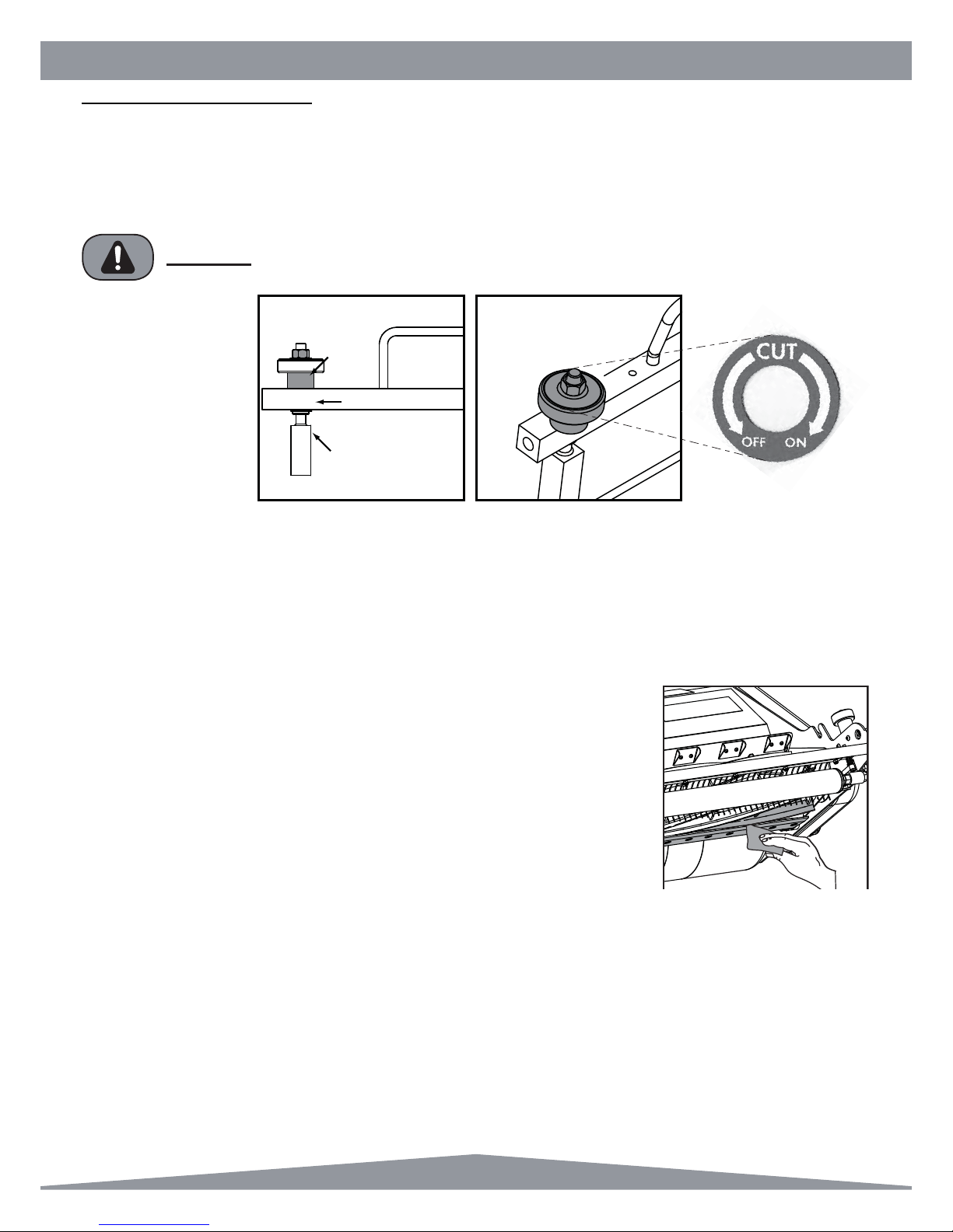
Set the height of cut to the required level (see page 9)
Check the engine.
Fill the fuel tank 3/4 full with unleaded petrol.
Always check the oil levels of the machine prior to commencing. Full details are given in the (1*,1( Manual, which
accompanies this book. A daily check is recommended. (Recommended grade oil is SAE 10W-40).
Disengage the cassette unit. (see next page)
Set the throttle control on the handle bars to the idle position.
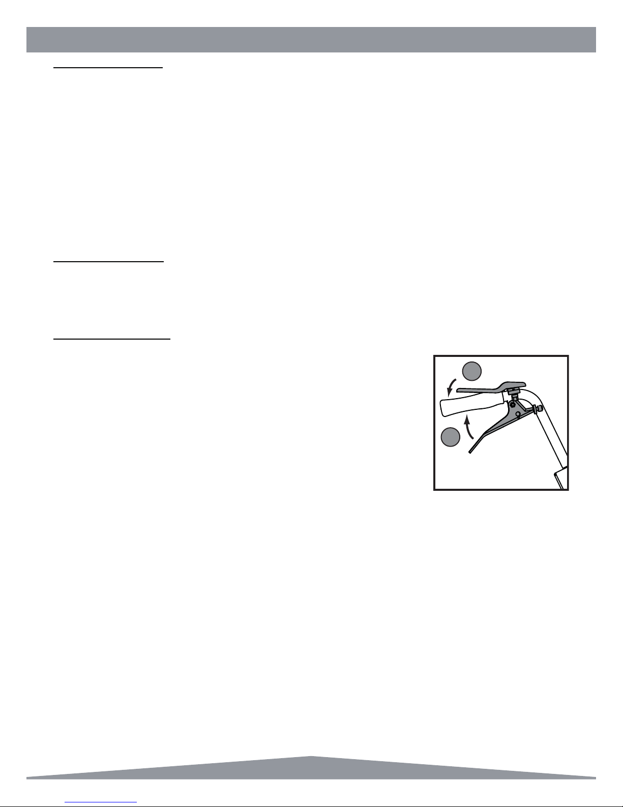
In the case of deadmans handle control depress the lever onto the handlebar then start the engine as per the
manufacturers instructions.
BEFORE YOU OPERATE THIS MACHINE YOU MUST READ AND STUDY THIS MANUAL.
IF YOU ARE IN ANY DOUBT PLEASE ASK YOUR EMPLOYER OR CONTACT US DIRECT.
&$87,21
IMPORTANT INFORMATION PLEASE READ ALL THE DETAILS IN THIS SECTION AND
FAMILIARIZE YOURSELF AND ALL MACHINE OPERATORS WITH THE CONTENTS.
&$87,21
*(1(5$/
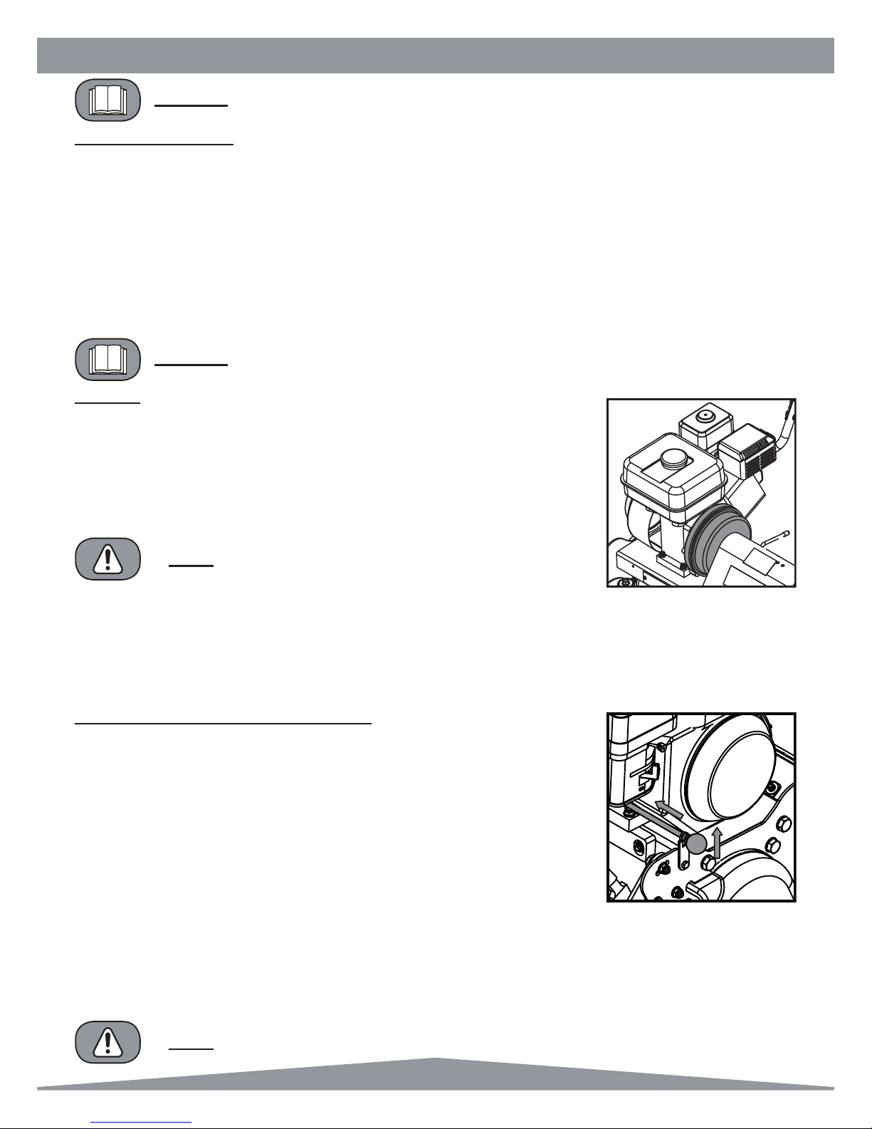
$FHQWULIXJDOFOXWFKLV¿WWHGLQWKHSULPDU\GULYHV\VWHP:KHQWKHHQJLQHUHYVDUHDW
tickover the clutch disengages and neither the cutter nor the rear roller controls will
function. Under these conditions the Deadmans Control can be released and the engine
will continue to tick over.
On increasing the revs of the engine with the throttle control the clutch engages thus
allowing cutter and roller to operate.
TO ASSIST THE SLOWING OF THE BLACK CENTRIFUGAL CLUTCH DRUM APPLY THE
BRAKE BAND LEVER.
NOTE
THE DEADMANS LEVER MUST BE DEPRESSED WHEN
INCREASING THE ENGINE REVS OR THE MACHINE
WILL STOP
NOTE
The drive to the cutter unit can be engaged or disengaged in one of two ways:-
A) By reducing the engine revs to tickover the centrifugal clutch will disengage. This method will be performed when
emptying the grassbox.
b) By having the dog drive disengaged. Use this method when transporting the machine.
When the centrifugal clutch is engaged the rear roller drive can be activated by the brake band lever.
75$163257'LVHQJDJLQJWKH&DVVHWWH'ULYH
To ensure the safety of operator and machine we strongly recommend disengaging the
cassette drive when transporting under power between sites. Do not operate any
cassettes with dog drive disengaged except for the sorrel roller, ironing roller and slitter.
This is achieved by performing the following procedure:
1)
Reduce engine revs to tickover. This will cause the black clutch drum to cease rotating.
2) Lift the red ball knob (attached to horizontal rod behind engine) and push towards the
machine. Locate the rod between the two nuts in the slotted catch plate.
3) Once in position the dog drive is disengaged.
To re-engage the dog clutch:
1) Reduce engine revs to tickover as above (1).
2) Lift control rod clear of the locating slot and allow it to spring back towards you.
3) Slowly increase engine revs until an audible click is heard when the dogs engage. Alternatively rotate the black clutch
drum about half a turn by hand and the same click will be heard. Do not rev the engine until the rod has moved right
across and fully engaged.

8
FT & Super Six SP20001_REV_4
67$57,1*7+((1*,1(
Once the preparatory steps have been completed as outlined on page 7 the engine may be started. (See manufacturer
operating manual for full details).
1) Switch on the fuel tap.
2) Switch the handlebar cut off switch to ON, or depress deadmans handle (Item 1)
3) Set the throttle control to a half open position.
3) Shift the choke lever to the appropriate position (Kubota engine set to 67$57 : Honda engine set to the &/26(
position). The choke is not required if the engine is warm or the air temperature high.
4) Grasp the recoil start handle until resistance is felt, then pull it with force.
5) Do not allow the starter grip to snap back against the engine. Return it gently to prevent damage to the starter.
6) Once the engine is started gradually ‘open’ the choke lever (move the lever towards the 5811,1*, or OPEN
position). Warm-up running of 3-5 minutes is recommended.
67233,1*7+((1*,1(
1) Set the throttle control to the &/26(' position.
2) Switch the handlebar cut off to OFF or switch off at engine.
3) Close the fuel tap.
72&200(1&(02:,1*
With the starting preparations completed and all of the adjustments from the ‘General
Adjustments’ section made, the machine can be put into motion.
Firstly ensure the dog clutch is engaged. Open the throttle control on the left handlebar
which will engage the inertia clutch and spin the cassette reel. The engine speed
controls the rotational velocity of the cassette. Set the throttle to an approximately half
open position.
To engage the rear roller drive, gently raise the driving clutch lever on the right handle
bar (Item 2). The amount of depression on the lever dictates the speed of travel giving
the operator total control over the speed and handling of the mower.
When the handle is released the machine will stop. To stop the unit head rotating, reduce the throttle to tick over and this
will disengage the inertia clutch.
1
2
2SHUDWLQJ,QVWUXFWLRQV

9
FT & Super Six SP20001_REV_4
As an indication coins measure the following:-
- 1p 1.58mm (0.063” ) - 2p 1.80mm (0.071” ) - 5p 1.73mm (0.067” )
- 10p 1.84mm (0.072” ) - 50p 1.84mm (0.072” ) - £1.00 3.14mm (0.124” )
Remember height of cut is effected by moisture of turf , weight of machine and the
thatch density. Different makes of machine cut at different heights when set to the
same position with the setting bar. We suggest you set it to a couple of mm above your
planned height and then come down in height by trial.
,IRQVHWWLQJWKHKHLJKWRIRSHUDWLRQ\RX¿QGLWQHHGVDOWHULQJRQFHRQWKHJUHHQVLPSO\
click the adjusters up or down the same on each side until the desired height of
operation is achieved.
Always check height of cut/operation with the setting bar provided. Check in two
positions i.e. one at either end of the cassette. Failure to do this could result in an
uneven cut.
*HQHUDO$GMXVWPHQWV
6(77,1*)25+(,*+72)&87
Always stop the engine before adjusting the height of cut. Failure
to do this may result in severe injury.
7KHOHQJWKRIJUDVVDIWHUFXWWLQJRUGHSWKRIVFDUL¿FDWLRQ
dethatching / brushing, depends on the setting of the front roller in
relation to the main frame of the machine.
FT
The Click system allows easy adjustment of the front roller postion
each click representing a change of 0.5mm (0.020”). The roller is
set to be equal on leaving the factory so when the arrows point forward on both decals the roller is level.
683(56,;
Adjustment to the height of the front roller is on the quadrant brackets at each end of the roller outisde the main frame
assembly. Undo the adjuster knob on each side of the mower and move the roller up or down and then re-tighten the
knobs. There are notches in the quadrant plates which must correspond with the hole in the side plate on both sides of
the mower to ensure the roller is level.
Check it is level using the setting bar between the front and rear roller with the underside of the screw ledging on the
bottom blade.
Either a ruler or pile of coins can be used to set the setting bar to the correct position. You are measuring the distance
between the bar and the underside of the button head screw (‘XX’ in the Image below).
DO NOT ATTEMPT TO USE THE DETHATCHER CASSETTE OR BRUSH CASSETTE ON
TOO LOW A SETTING AS THIS WILL DAMAGE THE BLADES AND BRUSH. DO NOT
ATTEMPT TO SCARIFY ON A LOW SETTING WHEN GROUND CONDITIONS ARE DRY AS
THIS MAY CAUSE THE CENTRIFUGAL CLUTCH TO SLIP.
NOTE
XX
410

10
FT & Super Six SP20001_REV_4
7KH)7F\OLQGHULV¿[HGLQ
position in self-aligning
bearings with aluminium
housings spigotted to the
side frames. The bottom
blade assembly is
adjusted up and down by
using a knurled knob
system.
To operate this system
¿UVWO\VODFNHQWKHWZRORFNQXWV
on the adjuster stems – The Lock Nut (A) is directly on top of the Knurled Knobs (B). Use a 9/16AF spanner. Each
knurled knob has a decal to indicate ON or OFF cut. ON cut brings the bottom blade closer to the cylinder. OFF cut
moves it away.
$ /RFNQXW´6SDQQHU
% /XEULFDWHRFFDVLRQDOO\ZLWK2LO
C = Circlip
Rotate the knurled knobs to gain light contact between the shear blade and cylinder on
both sides of the cassette. The adjustment should be made so that the cylinder will spin
with a light audible contact with the bottom blade. Check the setting using thin paper
along the length of the cylinder adjusting until it cuts along its whole length.
When a satisfactory set is achieved tighten the lock nuts whilst holding the knurled knob
¿UPO\WRVWRSLWWXUQLQJUHFKHFNDGMXVWPHQW
Do not set the cylinder hard on, as this will cause excessive wear of the cylinder, bottom
blade the drive system and increase fuel consumption.
*HQHUDO$GMXVWPHQWV
&877(56(77,1*$'-8670(17
For cutter cylinder cassettes (5 or 9 blade units).
)RUDIXOOYLHZRIWKHVHWWLQJRSHUDWLRQZHVXJJHVW\RXUHPRYHWKHFDVVHWWHIURPWKHPDFKLQHDQGSODFHRQWKHEDFNÀDW
edge of the frame at a comfortable height. It is now possible to make adjustments in the machine without cassette
removal should you prefer.
CYLINDERS AND BOTTOM BLADES ARE SHARP, WEAR GLOVES TO PROTECT YOUR
HANDS AND FINGERS.
:$51,1*

11
FT & Super Six SP20001_REV_4
*HQHUDO$GMXVWPHQWV
+$1'/(%$5$'-8670(17
The height of the Handle Bars can be adjusted to suit various operators. Follow the
below instructions:-
1. Remove Bolt (Item 1) on both sides of the machine.
2. Select the require position out of the 3 available.
3. Replace the Bolt on both sides of the machine.
*5$66%2;
If using the grass box, place the two locating tabs (projecting from the grass box support
plates) into the slots on the machine side plate. Lower the front of the box until the box support plate’s rest on the front
cross bar of the machine. Ensure both box support plates are properly located before proceeding.
Always disengage the cassette drive before removing the grass box for emptying or access by reducing the engine revs
to tick over. Wait for the cutter to stop before removing.
$OZD\VNHHS¿QJHUVDZD\IURPWKHFDVVHWWHZKHQWKHHQJLQHLVUXQQLQJ6WRSWKHPDFKLQHEHIRUHPDNLQJDQ\
adjustments.
+ROGWKHJUDVVER[¿UPO\RQWKHOLSRIWKHDSHUWXUHDQGSODFHWKHRWKHUKDQGLQWKHKDQGOHRQWKHIURQWHGJHRIWKHER[
A
Item 1

12
FT & Super Six SP20001_REV_4
5HPRYLQJ7KH&DVVHWWH8QLW
To remove the cassette unit for maintenance or to exchange cassettes the following
procedure should be followed:-
1) Unscrew the hand wheel of the retaining pin for about half-an-inch (13mm) until the
pip end is inside the nut on the side frame.
2) Slide the cassette unit along the tie bars as far as it will go until the cutter nut and
coupling is clear of the three pins in the driving coupling.
3) Remove the unit from the chassis by lifting in a swinging motion from the back.
To replace the cassette unit :-
1) Place the front slots of the cassette unit frames on the two front retaining pins seen
projecting from inside each frame.
2) Carefully lower the unit in a downward swinging motion until the rear slots of the
cassette unit frame rest on the cross tie bar.
3) Move in a lateral direction away from the retaining pin until the three holes of the
cassette nut and coupling are in full engagement with the three pins of the driving
coupling.
4) Screw up the hand wheel with the retaining pin, engaging the hole in the side frame
on the opposite side. Do not over tighten.

13
FT & Super Six SP20001_REV_4
5RXWLQH0DLQWHQDQFH
'5,9,1*%(/76
The main drive to both rear roller and cassette is via hard wearing TBApoly-V type belts
which provide for smooth trouble free operation. To ensure the best performance the
following instructions should be carefully followed.
Belt tension is the single most important factor necessary for long, satisfactory service
life of any belt drive.
Under-tensioning leads to belt slip causing rapid wear; over tensioning means
excessive strain on belt and bearings. Between these two extreme conditions is a
reasonable range of tension within which the belt will operate. Belt tension can be
DVVHVVHGE\WKHµGHÀHFWLRQ¶PHWKRG
CORRECTION CAN BE MADE BY ADJUSTMENT OF THE BELT TENSIONERS. REMOVE
THE DRIVING BELT COVER. THE BELT TENSIONERS ARE RETAINED IN A SLOTTED
HOLE ALLOWING ADJUSTMENT TO BE MADE ONCE THE HOLDING HEXAGON
HEADED BOLTS HAVE BEEN LOOSENED. WHEN ADJUSTED CORRECTLY THE
TENSIONERS SHOULD STILL ROTATE EASILY WITH FINGER PRESSURE. ENSURE THE
TENSIONER BOLTS ARE SECURE BEFORE REPLACING THE COVER.
NOTE
³%HOWVZLOOEHVXI¿FLHQWO\WHQVLRQHGLIWKHGHÀHFWLRQIRUFHDSSOLHGDWPLGVSDQWRSURGXFHDGHÀHFWLRQHTXDOWRPPSHU
meter of span distance falls between 5 and 9 Newtons per Rib” (TBA Belting).
,QSUDFWLFDOWHUPVWKLVUHODWHVWRDERXWPPRIGHÀHFWLRQXQGHUPRGHUDWH¿QJHUSUHVVXUHRQWKHQRQWHQVLRQHUVLGH
,I¿WWLQJQHZEHOWVLWLVDGYLVDEOHWRREVHUYHWKHGULYHIRUWKH¿UVWPLQXWHV,WPD\EHQHFHVVDU\WRPDNHDQ
adjustment to compensate for the normal drop in tension during the run-in period.
)25%(/7'(7$,/65()3J
Do not overtighten belts as this may cause excessive wear on the dog clutch.
2,/)8(/7<3(48$17,7<63$5.3/8*7<3(
Engine Model Oil Type Quantity
(Ltr) Fuel Type Capacity
(Ltr) Spark Plug Type Electrode Gap
(mm)
Honda GX120 &
GX160 Petrol SAE 10W-40 0.6 Unleaded 2.5 BM6ES or BPR6ES 0.7 - 0.8
Area Maintenance First 4 Hours First Month / 20 Hours 3 Months / 50 Hours 6 Months / 100 Hours
Engine Oil Check Level 9
Engine Oil Change 99
Air Filter Check Condition /
Clean 99
Spark Plug Change 9
(1*,1(
7KH)7LV¿WWHGZLWKD+RQGD*;*;RQ)7SHWUROHQJLQH$OODUHVLQJOHF\OLQGHURYHUKHDGYDOYHVWURNH
IRUFHGDLUFROOHGHQJLQHV)RUIXOOVSHFL¿FDWLRQVSOHDVHUHIHUWRWKHPDQXIDFWXUHUVLQVWUXFWLRQPDQXDOLQFOXGHG

14
FT & Super Six SP20001_REV_4
5RXWLQH0DLQWHQDQFH
%5$.(%$1'$'-8670(175HDU$[OH'ULYH
The brake band assembly is mounted on the end of the rear axle spindle on the right
hand side of the machine. The assembly comprises a cast iron drum inner member,
which is stopped or braked with a lined steel brake band. This operates dry and no
lubrication of any kind is required.
Adjustment is provided for tightening the band on the inner member should this be
necessary through wear. The procedure to take up any slack is as follows :-
1. Remove the clutch cover by unscrewing the two hexagon headed screws seen on the
outside of the cover.
2. Unscrew the lock nut on the adjuster screw situated between the two clutch band lugs.
ENSURE THE LOCK NUTS ARE TIGHT AND SECURE AND CHECK OPERATION IS
SATISFACTORY BEFORE REPLACING THE CLUTCH COVER AND SCREWS.
NOTE
$GMXVW+HUH
$GMXVWPHQWRIWKHEUDNHEDQGFDQEHVHWWRVXLW\RXUSUHIHUHQFHEXWDOZD\VHQVXUHWKDWWKHUHLVVXI¿FLHQWIUHHSOD\VRWKDW
when the engine revs are increased the machine does not move in any way until the lever is pulled up.
On some models there is adjustment on the handle grip itself to allow any wear to be taken up.

15
FT & Super Six SP20001_REV_4
*HQHUDO/XEULFDWLRQ
5($552//(5
The centre section gear case chamber of the rear roller is an assembly in two halves and contains the epicyclic gear
system, which runs in an oil bath.
7KHFKDPEHULVFKDUJHGZLWKJHDURLO(3EHIRUHWKHPDFKLQHOHDYHVWKHZRUNVDQGVKRXOGUHTXLUHQRIXUWKHU¿OOLQJ
during the cutting season. If in every day use then a topping up charge of about one egg cup full every two months may
be appropriate.
DO NOT OVERCHARGE. AT NO TIME SHOULD THERE BE MORE THAN 100CC OF OIL
IN THE CHAMBER.
:$51,1*
Access to the chamber is gained by unscrewing the hexagon screw found in the recess of the centre section of roller.
Clean away all dirt and grit before removing this screw. On replacing the screw, make sure it is tight and secure.
Recommended grade gearbox oil EP90.
5$7&+(73$:/6$1''580+8%62)7+(5($552//(5(YHU\0RQWKV
Projecting from the side face towards the centre of each outer drum will be seen two
grease nipples which provide access for lubrication to the rear roller driving pawls and
the drum hub bearing sleeve.
A small charge of light grease should be applied every two months.
)521752//(56
The bearings used on the front rollers are pre packed with grease and rubber shielded,
therefore requiring no additional greasing.
&</,1'(5&$66(77(%($5,1*6(YHU\'D\
7RDSSO\OXEULFDWLRQWRWKHF\OLQGHUFDVVHWWHEHDULQJVLWLV¿UVWQHFHVVDU\WRUHPRYHWKH
cassette unit from the chassis as described on page 9.
Projecting from each bearing cover will be seen a grease nipple through which a small
charge of grease should be applied using the grease gun
0(',80*5($6( *22'48$/,7<
6&$5,),(5'(7+$7&+(5%586+&$66(77(6
No grease or oiling is required.

16
FT & Super Six SP20001_REV_4
*HQHUDO/XEULFDWLRQ
'2*'5,9((YHU\'D\9(5<,03257$17
Apply a small squirt of lubricating oil (2-3 drops) directly into each hole in the top of the
drive shaft cover. This keeps the clutch slippers lubricated.
&21752//(9(56$1'&$%/(6(YHU\0RQWKV
To keep the controls free from rust and corrosion apply a small charge of oil to the
WKURWWOHDQGFOXWFKFRQWUROOHYHUVHYHU\WZRPRQWKV2LOÀRZFDQEHDVVLVWHGE\ZRUNLQJ
the levers open and closed a few times after the lubrication is applied.
)521752//(5$'-867(56(YHU\0RQWKV
Apply a small quantity of copper grease or similar to the adjuster studs to prevent corrosion and ease adjustment.
/XEULFDWH
'DLO\
6WRUDJH
The machine should always be kept in a clean dry place, free from condensation. After use ensure that the machine is
thoroughly clean, dry and free from grass and mud. Before off season storage smear a thin layer of grease on to the
cutter blades and the shear blade.
Under no circumstances must the machine be steam cleaned as this may remove grease from the pre packed bearings.
Because of the nature of lead free petrol we recomend that if the machine is being left unused for more than 2 weeks the
carburetor is run dry. Allow the engine to run out of fuel with the fuel tap switched off.
*XLGH7R5HSODFHPHQW3DUWV
WHEN ORDERING PARTS PLEASE QUOTE YOUR MACHINE SERIAL NUMBER AND
ENGINE NUMBER. A BOX TO ENTER THESE FOR EASY REFERENCE IS AT THE
BEGINNING OF THE MANUAL.
NOTE
This manual contains listing of parts for the Dennis FT430, FT510 and FT610 machines. An illustration of the parts as an
assembly is shown above the list.
Where parts are given a description of LH or RH (left hand or right hand) this is as viewed from the users position.
The Parts Listings for FT Range can be found in this manual from page 18 onwards.

17
FT & Super Six SP20001_REV_4
)7*XLGHWR&DVVHWWH8VH
RESULT - Speed improvement on greens,reduced end of season maintenance. Promotes healthy plant growth, promotes
strong roots, and maximizes fertilizer penetration.
6&$5,),(56((3$*(
Used for ground to ground -10mm controlling thatch, removing thatch, cutting lateral growth, pruning roots, removing
moss, aerating top layer for ingress of water, air, fertilizer and seed. Choice of 1mm or 2mm thick blades (generally 1mm
used in summer, 2mm used in winter). Do not try to cut too deep - must be adjusted to suit conditions.
Keep engine revs reasonably high with a slow forward movement to remove as much material as possible. The machine
may tend to walk along on its own in some conditions.
RESULT - Speed increase of playing surface. Maximizes fertilizer penetration & promotes strong healthy plant growth and
strong roots.
%586+6((3$*(
Used for light scarifying, brushing, removing debris, cigarette ends, pine needles moss, excess top dressing etc. Set at
+3mm to +1mm for ground debris depending on conditions. Remove comb.
,521,1*52//(5121'5,9(11276+2:1
Ballastable for extra weight. Used for ironing greens. Set level or lift up front roller.
6255(/52//(5127'5,9(16((3$*(
Used for surface pricking. Lets air, water, fertilizer into the root zone. Good for over seeding and preparing damaged
areas for repair. Reduces surface tension.
%/$'(&</,1'(56((3$*(
)RUFXWWLQJ¿QHWXUIDUHDV
7KUHHERWWRPEODGHRSWLRQV
&RPEDFWLYHRUSDVVLYH
%/$'(&</,1'(56((3$*(
)RUJHQHUDOSXUSRVHFXWWLQJ
&RPEDFWLYHRUSDVVLYH
Settings - Expressed as above and below ground level i.e. by placing the setting bar between the front and rear rollers,
the top of the bar represents ground level.
9(57,&877(56((3$*(
Used from ground +3mm to ground -3mm to control thatch, cutting lateral growths and standing up lying grasses ready for
cutting and lifting with the comb. Good for removing mosses. Start on the green at (say) +3mm.
NOT FOR CUTTING SOIL, ONLY THATCH.
NOTE
Bowls Cricket Golf
Verticutter Monthly Fortnightly Monthly
6FDULÀHU 1 - 2 Months 1 - 2 Months 1 - 2 Months
Brush As Required As Required As Required
Ironing roller Match Days Pre-Season As Required
Sorrel Roller 1 - 2 Weeks Monthly (As Required for Repair) Monthly (As Required for Repair)

18
FT & Super Six SP20001_REV_4
,WHP1R 3DUW1R 'HVFULSWLRQ 4XDQWLW\
1 229492 Retaining Plate Assy 2
2 230004 Support Bracket 1
3 230006 Support Plate Engine 1
4 800020 FT L.H. Side Plate Assembly 1
5 800021 FT R.H. Side Plate Assy 1
6 J20222 Cork Buffer 1
7 800104 Stop Pin Assy 1
8 J17235 Front Cross Bar (17”) 1
8 J20235 Front Cross Bar (20”) 1
8 J24235 Front Cross Bar (24”) 1
9 J17236 Lower Unit Tie Bar (17”) 1
9 J20236 Lower Unit Tie Bar (20”) 1
9 J24236 Lower Unit Tie Bar (24”) 1
10 J20263 Front Stud Spacer 1
11 J20292 Collar Front Tie Bar 2
12 J20297 Serial Number Plate 1
13 J209053 Support Plate 1
14 J209059 Gate 1
15 J179215 Engine Bed (17”) 1
15 J209215 Engine Bed (20”) 1
15 J249215 Engine Bed (24”) 1
16 SP01009 Hex Set Screw M8 x 20 2
17 SP01011 Hex Set Screw 3/8” UNF x 3/4” 2
18 SP01053 Hex Set Screw 1/2” UNF x 1” 10
19 SP01055 Hex Taptite Screw M6 x 16 2
20 SP02006 Nut M8 Nyloc 7
21 SP03015 Washer M8 Form C 8
22 SP03023 Washer 1/2” Toothed 8
23 SP05001 Rivet 4.8 x 10 2
24 228094 End Tip 5/16” 1
25 J17251 Rear Scraper Bar Assy (17”) 1
25 J20251 Rear Scraper Bar Assy (20”) 1
25 J24251 Rear Scraper Bar Assy (24”) 1
26 J209056 Hand Brake Lever 1
27 J209057 Brake 1
28 SP05014 Clevis Pin 3/8” x 2 1/2” 1
&KDVVLV0DLQ$VVHPEO\
20
20
19
14
31
8
6
10
9
1
12
23
18
11
17
22
18
5
15
21
18
4
21
16
16
21
20
20
21
13
11
20
28
29
27
26
24
30
25
31
2
,WHP1R 3DUW1R 'HVFULSWLRQ 4XDQWLW\
29 SP05010 Split Pin 1/8” x 1” 1
30 SP03008 Washer M8 FormA 1
31 800104 Cassette Retaining Screw 1

19
FT & Super Six SP20001_REV_4
&KDVVLV/+6LGH3ODWH
,WHP1R 3DUW1R 'HVFULSWLRQ 4XDQWLW\
1 J209253 Side Plate LH (FT) 1
1 J209218 Side Plate LH (Super Six) 1
2 229741 Buffer Block 1
3 229742 Buffer 1
4 J209072 Chain Case Stud ( > 08/2010) 2
5 J20216 Unit Limiting Stud 1
6 J20238 Shoulded Gearing Stud (FT) 1
6 J209110 Unit Bearing Stud (Super Six) 1
7 J20008 Back Plate With Hole 1
8 J20221 Male Coupling 1
9 J209203 Cassette Driven Pulley / Shaft 1
10 J209206 Cassette Drive Bearing Housing 1
11 J20255 Bearing 5205 - 3205 2RS 1
12 J20023 Unit Limiting Stud 1
13 SP03008 Washer M8 FormA 3
14 J209043 Tensioner Back Plate 2
15 J209047 Tensioner Pulley ( > 08/2010) 2
16 J209049 Spacer Roller Tensioner ( > 08/2010) 1
17 SP01008 Hex Set Screw M6 x 16 2
18 SP01012 Button Head M8 x 12 3
19 SP02006 Nut M8 Nyloc 4
20 SP03003 Washer M6 Toothed 2
21 SP01013 Hex Set Screw 3/8” UNF x 2” 1
22 SP02015 Nut 3/8” UNF 3
23 SP01057 Screw 3/8” UNF x 3 1/4” ( > 08/2010) 1
24 SP02008 Nut M10 Nyloc 2
25 SP03011 Washer M10 Form A 2
26 230490 Belt Tensioner ( < 08/2010) 1
27 230493 Pulley Retainer ( < 08/2010) 1
28 J209047 Tensioner Pulley ( < 08/2010) 1
29 SP01056 CSK Cap Head M6 x 25 ( < 08/2010) 1
30 SP02006 Nut M8 Nyloc ( < 08/2010) 1
31 SP03008 Washer M8 Form A ( < 08/2010) 1
32 800222 Belt Tensioner Assembly ( < 08/2010) 1
(Includes Items 26, 27, 28, 29, 30, 32)
AA
A
B
13
22
14
19
13
32
12
14
22
19
6
8
18
7
5
17
20
19
13
15
21
25
24
4
25
24
1
9
11
10
4
23
15
16
26
28
31
30
29
27
> 08/2010
1RW6KRZQ
- J209003 3 Groove Drive Belt (Rear Roller) 1
- J209005 5 Groove Drive Belt (Cylinder) 1

20
FT & Super Six SP20001_REV_4
&KDVVLV5+6LGH3ODWH
,WHP1R 3DUW1R 'HVFULSWLRQ 4XDQWLW\
1 J209254 Side Plate RH (FT) 1
1 209219 Side Plate RH (Super Six) 1
2 J20023 Unit Limiting Stud 1
3 229741 Buffer Block 1
4 229742 Buffer 1
5 SP03003 Washer M6 Toothed 2
6 SP01008 Hex Set Screw M6 x 16 3
7 J209229 Clutch Rod Stop 1
8 J209078 Retaining Screw Plate 1
9 SP01016 Button Head M6 x 12 2
10 J20207 Stud Brake Band Cover 2
11 J20237 Unit Bearing Stud (FT) 1
11 J209110 Unit Bearing Stud (Super Six) 1
12 SP02006 Nut M8 Nyloc 4
13 SP02004 Nut M6 Nyloc 1
14 SP03010 Washer M6 FormA 1
15 SP02008 Nut M10 Nyloc 1
16 SP03008 Washer M8 FormA 3
17 SP03011 Washer M10 Form A 1
7
15
17
8
10
10
6
5
12
16
6
1
4
3
12
12
16
9
11
12
16
13
14
2
This manual suits for next models
2
Table of contents
Other Dennis Lawn Mower manuals

Dennis
Dennis Simplex 510 User manual

Dennis
Dennis PRO 34R User manual

Dennis
Dennis Simplex User manual

Dennis
Dennis E Series User manual

Dennis
Dennis Premier 30" User manual

Dennis
Dennis FT 610 User manual

Dennis
Dennis Razor Ultra 560 User manual

Dennis
Dennis E Series User manual

Dennis
Dennis FT User manual

Dennis
Dennis G-SERIES User manual