manuals.online logo
Brands
  1. Home
  2. •
  3. Brands
  4. •
  5. Denon
  6. •
  7. Amplifier
  8. •
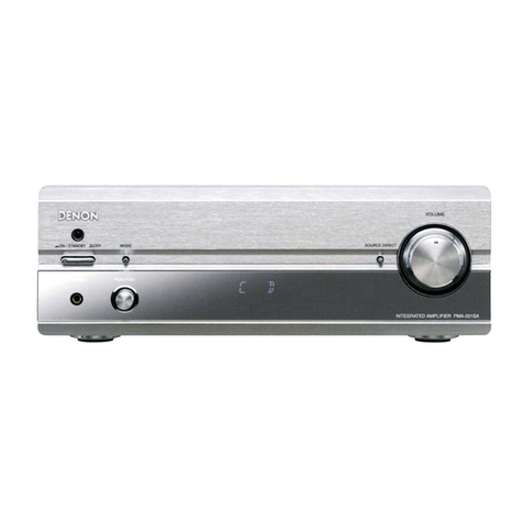
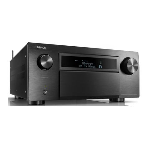
  9. Denon AVR-1705 User manual

Denon AVR-1705 User manual

Other manuals for AVR-1705

4

This manual suits for next models

1

Other Denon Amplifier manuals

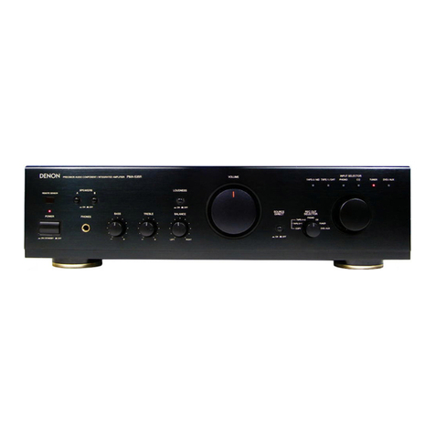
Denon HEOS HS2 User manual

Denon

Denon HEOS HS2 User manual

Denon POA-F100 User manual

Denon

Denon POA-F100 User manual

Denon DN-470A User manual

Denon

Denon DN-470A User manual

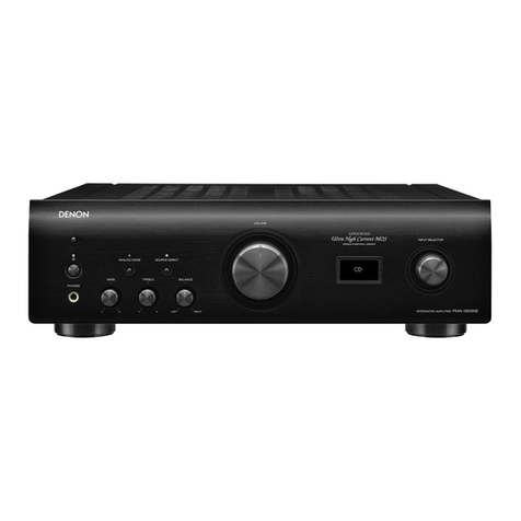
Denon PMA-2020AE User manual

Denon

Denon PMA-2020AE User manual

Denon PMA-1510AE User manual

Denon

Denon PMA-1510AE User manual

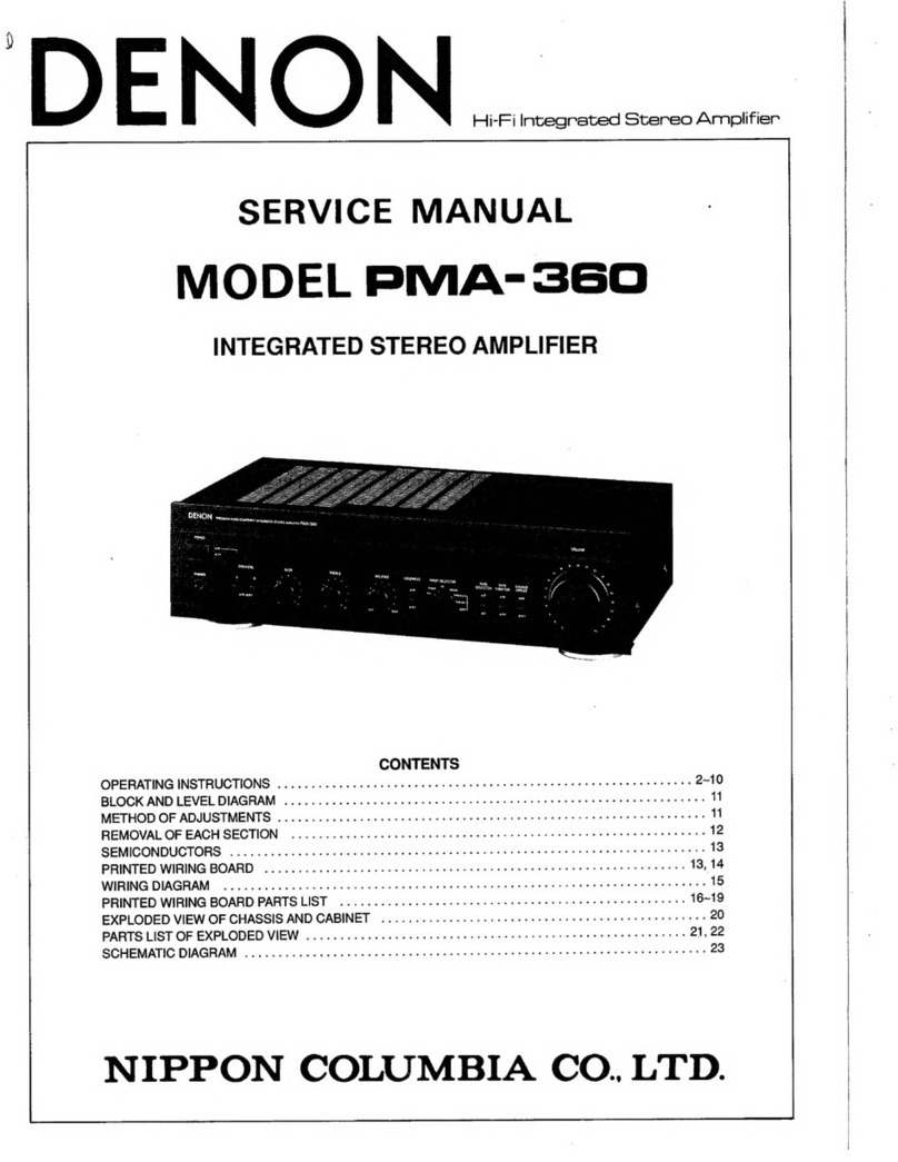
Denon PMA-830 User manual

Denon

Denon PMA-830 User manual

Denon POA-2200 User manual

Denon

Denon POA-2200 User manual

Denon POA-S1 User manual

Denon

Denon POA-S1 User manual

Denon AVC-A11SR Assembly instructions

Denon

Denon AVC-A11SR Assembly instructions

Denon PMA-777 User manual

Denon

Denon PMA-777 User manual

Denon DN-A100 User manual

Denon

Denon DN-A100 User manual

Denon PMA-2000IVR User manual

Denon

Denon PMA-2000IVR User manual

Denon PMA-700V User manual

Denon

Denon PMA-700V User manual

Denon AMPHS2SRE2 User manual

Denon

Denon AMPHS2SRE2 User manual

Denon DN-500AV User manual

Denon

Denon DN-500AV User manual

Denon POA-3012CI - Multi-Zone Audio Distribution Power... User manual

Denon

Denon POA-3012CI - Multi-Zone Audio Distribution Power... User manual

Denon AVC-A11SR User manual

Denon

Denon AVC-A11SR User manual

Denon PMA-510AE User manual

Denon

Denon PMA-510AE User manual

Denon PMA-535R User manual

Denon

Denon PMA-535R User manual

Denon PMA-495R Quick start guide

Denon

Denon PMA-495R Quick start guide

Denon DN-A7100 - AV Surround Preamplifier User manual

Denon

Denon DN-A7100 - AV Surround Preamplifier User manual

Denon AVC-A1H User manual

Denon

Denon AVC-A1H User manual

Denon PMA-900HNE User manual

Denon

Denon PMA-900HNE User manual

Denon AVC-X4700H User manual

Denon

Denon AVC-X4700H User manual

Popular Amplifier manuals by other brands

Magnat Audio EDITION FOUR Owner's manual/warranty document

Magnat Audio

Magnat Audio EDITION FOUR Owner's manual/warranty document

Inter-m PA-2000A Operation manual

Inter-m

Inter-m PA-2000A Operation manual

Yamaha TX6n owner's manual

Yamaha

Yamaha TX6n owner's manual

Peavey TNT 150 user guide

Peavey

Peavey TNT 150 user guide

Bosch LBB 1903/10 Installation and user instructions

Bosch

Bosch LBB 1903/10 Installation and user instructions

Avocent Emerge DA1200D Installer/user guide

Avocent

Avocent Emerge DA1200D Installer/user guide

Redgum RGi35 operating instructions

Redgum

Redgum RGi35 operating instructions

Cambridge Audio AXA25 user manual

Cambridge Audio

Cambridge Audio AXA25 user manual

Alpine MRP-M200 owner's manual

Alpine

Alpine MRP-M200 owner's manual

Technical Pro H1502UrBT user manual

Technical Pro

Technical Pro H1502UrBT user manual

FMS EMGZ307 operating manual

FMS

FMS EMGZ307 operating manual

Racal Instruments 5601 user manual

Racal Instruments

Racal Instruments 5601 user manual

Valcom V-1094A Technical specifications

Valcom

Valcom V-1094A Technical specifications

Cambridge Audio 851D user manual

Cambridge Audio

Cambridge Audio 851D user manual

QSC 3800 Specifications

QSC

QSC 3800 Specifications

NAD C300 owner's manual

NAD

NAD C300 owner's manual

Rotel RMB-1077 owner's manual

Rotel

Rotel RMB-1077 owner's manual

Peavey Monitor 300 Series operating guide

Peavey

Peavey Monitor 300 Series operating guide

manuals.online logo
manuals.online logoBrands
  • About & Mission
  • Contact us
  • Privacy Policy
  • Terms and Conditions

Copyright 2025 Manuals.Online. All Rights Reserved.

SERVICE MANUAL
MODEL
AVR-1705/685
AV SURROUND RECEIVER/AMPLIFIER
For U.S.A., Canada, Europe,
China & Taiwan R.O.C. model
16-11, YUSHIMA 3-CHOME, BUNKYO-KU, TOKYO 113-0034 JAPAN
X0202 V.01 DE/CDM 0406
Some illustrations using in this service manual are
slightly different from the actual set.
●
Please use this service manual with referring to the
operating instructions without fail.
●
For purposes of improvement, specifications and
design are subject to change without notice.
●
●
 
本文中に使用しているイラストは、説明の都合上現物
 
 
と多少異なる場合があります。
●
 
修理の際は、必ず取扱説明書を参照の上、作業を行っ
 
 
てください。
サービスをおこなう前に、このサービスマニュアルを
必ずお読みください。本機は、火災、感電、けがなど
に対する安全性を確保するために、さまざまな配慮を
おこなっており、また法的には「電気用品安全法」に
もとづき、所定の許可を得て製造されております。
従ってサービスをおこなう際は、これらの安全性が維
持されるよう、このサービスマニュアルに記載されて
いる注意事項を必ずお守りください。
●
 
本機の仕様は性能改良のため、予告なく変更すること
 
 
があります。
●
 
補修用性能部品の保有期間は、製造打切後8年です。
注 意
Ver. 1
w
w
w
.
x
i
a
o
y
u
1
6
3
.
c
o
m
Q
Q
3
7
6
3
1
5
1
5
0
9
9
2
8
9
4
2
9
8
T
E
L
1
3
9
4
2
2
9
6
5
1
3
9
9
2
8
9
4
2
9
8
0
5
1
5
1
3
6
7
3
Q
Q
TEL 13942296513 QQ 376315150 892498299
http://www.xiaoyu163.com
2
AVR-1705/685
SAFETY PRECAUTIONS
The following check should be performed for the continued protection of the customer and service technician.
LEAKAGE CURRENT CHECK
Before returning the unit to the customer, make sure you make either (1) a leakage current check or (2) a line to chassis
resistance check. If the leakage current exceeds 0.5 milliamps, or if the resistance from chassis to either side of the
power cord is less than 460 kohms, the unit is defective.
(1)
(2)
500V
1M
(1)
(2)
w
w
w
.
x
i
a
o
y
u
1
6
3
.
c
o
m
Q
Q
3
7
6
3
1
5
1
5
0
9
9
2
8
9
4
2
9
8
T
E
L
1
3
9
4
2
2
9
6
5
1
3
9
9
2
8
9
4
2
9
8
0
5
1
5
1
3
6
7
3
Q
Q
TEL 13942296513 QQ 376315150 892498299
http://www.xiaoyu163.com
3
AVR-1705/685
DIMENSION
w
w
w
.
x
i
a
o
y
u
1
6
3
.
c
o
m
Q
Q
3
7
6
3
1
5
1
5
0
9
9
2
8
9
4
2
9
8
T
E
L
1
3
9
4
2
2
9
6
5
1
3
9
9
2
8
9
4
2
9
8
0
5
1
5
1
3
6
7
3
Q
Q
TEL 13942296513 QQ 376315150 892498299
http://www.xiaoyu163.com
4
AVR-1705/685
CAUTION IN SERVICING
Initializing AV SURROUND RECEIVER
AV SURROUND RECEIVER initialization should be performed
when the µcom, peripheral parts of µcom, and Digital P.W.B. are
replaced.
1. Switch off the unit.
2. Hold the following SPEAKERS-A button and SPEAKERS-B
button, and switch on the unit.
3. Check that the entire display is flashing with an interval of
about 1 second, and release your fingers from the 2 buttons
and the microprocessor will be initialized.
Note:・If step 3 does not work, start over from step 1.
・
All user settings will be lost and this factory setting will
be recovered when this initialization mode.
So make sure to memorize your setting for restoring
after the initialization.
サービス時の注意事項
AVサラウンドアンプの初期化について
マイコンやマイコン周辺部品、Digital 基板等を交換した場合
は、AV サラウンドアンプの初期化を行って下さい。
1. オン/オフボタンを OFF にします。
2. SPEAKERS-A ボタンと SPEAKERS-B ボタンを同時に押しな
がら、オン/オフボタンを押して ON にします。
3. ディスプレイ表示が約 1秒間隔で点滅するのを確認後、2
つのボタンから指を離します。
*マイコンが初期化されます。
注意 :・上記 3 の状態にならない場合は、もう一度操作 1 か
らやり直してください。
・初期化を行うとお客様が設定した内容が工場出荷状
態に戻りますので、あらかじめ設定内容を控えてお
き初期化後再設定してください。
w
w
w
.
x
i
a
o
y
u
1
6
3
.
c
o
m
Q
Q
3
7
6
3
1
5
1
5
0
9
9
2
8
9
4
2
9
8
T
E
L
1
3
9
4
2
2
9
6
5
1
3
9
9
2
8
9
4
2
9
8
0
5
1
5
1
3
6
7
3
Q
Q
TEL 13942296513 QQ 376315150 892498299
http://www.xiaoyu163.com
5
AVR-1705/685
ADJUSTMENT
Audio Section
Idling Current
Required measurement equipment: DC Voltmeter
1. Preparation
(1) Avoid direct blow from an air conditioner or an electric
fan, and adjust the unit at normal room temperature 15 °C
~ 30 °C (59 °F ~ 86 °F).
(2) Presetting
• POWER (Power source switch) OFF
• SPEAKER (Speaker terminal) No load
(Do not connect speaker, dummy resistor, etc.)
2. Adjustment
(1) Remove top cover and set VR101, VR102, VR103,
VR104, VR105, on Amp. Unit, VR106 on SURR.-BACK
ch Amp. Unit at fully counterclockwise ( ) position.
(2) Connect DC Voltmeter to test points (FRONT-Lch:
TP104, FRONT-Rch: TP105, CENTER ch: TP103, SUR-
ROUND-Lch: TP101, SURROUND-Rch: TP102, SUR-
ROUND-BACK ch: CP106).
(3) Connect power cord to AC Line, and turn power switch
"ON".
(4) Presetting.
MASTER VOLUME : "---" counterclockwise ( min.)
MODE : 6CH STEREO
FUNCTION : CD
(5) Within 2 minutes after the power on, turn VR101 clock-
wise ( ) to adjust the TEST POINT voltage to 1.5 mV
± 0.5 mV DC.
(6) After 10 minutes from the preset above, turn VR101 to
set the voltage to 2.5 mV ± 0.5 mV DC.
(7) Adjust the Variable Resistors of other channels in the
same way.
VR104
TP104
VR101,TP101
VR106
CP106
VR103,TP103
VR102
TP102
VR105
TP105
F Lch
S Lch
S Back ch
C ch
S Rch
F Rch
DC Voltmeter
調整
オーディオセクション
アイドリング電流の調整
調整に必要な測定器 : DCVoltmeter
1. 準備
(1) セットをクーラ、扇風機のそばなど風通しの良い場所
を避け、通常の使用状態に置きます。セットの周囲温
度は 15〜30 ℃、湿度は常湿とします。
(2) プリセット
・電源スイッチ OFF
・スピーカ端子 無負荷
( スピーカ・ダミー抵抗器などを接続しない。)
2. 調整
(1) 上カバーをはずし、パワーアンプ基板の VR101,VR102,
VR103,VR104,VR105 及び SURR.-BACK アンプ基板の
VR106 を反時計方向 ( )に回し切った状態にセット
します。
(2) テストポイント (FRONT-Lch:TP104,FRONT-Rch:
TP105,CENTERch:TP103,SURROUND-Lch:TP101,
SURROUND-Rch:TP102,SURROUND-BACKch:CP106)
に DCVoltmeterを接続します。
(3) 電源コードを AC100V(95〜105Vの範囲でも可)に接
続し、電源スイッチを "ON"にします。
(4) ON後、次のようにセットします。
・MASTERVOLUME(音量調節つまみ)→反時計方向
( )に回す、最小の状態にする。
・SPEAKER(スピーカ端子)→無負荷(スピーカ、
ダミー抵抗器などを接続しない。)
MODE:6CHSTEREO 
FUNCTION:CD
(5) 2分以内に VR101を時計方向 ( ) に回しテストポイ
ントの電圧を次のように調整します。
1.5mV ±0.5mVDC
(6) 予備調整から 10分後 VR101を回し、次のように電圧を
設定します。
2.5mV± 0.5mVDC
(7) 同じ方法で各チャネルの可変抵抗を調整します。
w
w
w
.
x
i
a
o
y
u
1
6
3
.
c
o
m
Q
Q
3
7
6
3
1
5
1
5
0
9
9
2
8
9
4
2
9
8
T
E
L
1
3
9
4
2
2
9
6
5
1
3
9
9
2
8
9
4
2
9
8
0
5
1
5
1
3
6
7
3
Q
Q
TEL 13942296513 QQ 376315150 892498299
http://www.xiaoyu163.com
6
AVR-1705/685
Video Section
Component Video Level Adjustment
Required measurement equipment etc.: Oscilloscope, DVD
VIDEO PLAYER (ex: DVD-1500)
Test disc: DVD T-S01
1. Preparation
(1) Avoid direct blow from an air conditioner or an electric
fan, and adjust the unit at normal room temperature 15 °C
~ 30 °C (59 °F ~ 86 °F).
(2) Playback the color-bar 75% of the Test Disc (Title 12) us-
ing the DVD Video Player, and check that Y and C levels
of the S terminal output are within the specified output
levels.
If they are out of the specified levels, adjust with the vari-
able resister inside of the unit.
(3) Presetting
• POWER (Power source switch) OFF
• SPEAKER (Speaker terminal) No load
(Do not connect speaker, dummy resistor, etc.)
• DVD (Video terminal) No input
2. Adjustment
(1) Remove top cover and set VR601, VR602, VR603, on C-
S VIDEO2 Unit at fully counterclockwise ( ).
(2) Connect a pin-plug terminated with 75-ohms to Y (Cb, Cr)
of the Component Video Monitor Output, and hook up the
Oscilloscope’s probe to both ends of the pin-plug.
(3) Connect S terminal output of the DVD Player with the
DVD input terminal of the Receiver.
(4) Connect power cord to AC Line, and turn power switch
"ON".
(5) Presetting.
• FUNCTION: DVD
• Playback the color-bar 75% of the Test Disc (Title 12)
(6) Turn VR601 clockwise ( ) to adjust the COMPONENT
Video Y voltage (except H. Sync) to 714 ± 50 mVp-p. (Re-
fer to Fig. 1)
(7) Adjust the Variable Resistors of Cr: VR602 and Cb:
VR603 in the same way. (Refer to Fig. 2, 3)
Cb,Cr: 486 ± 50 mVp-p. (U.S.A. & Canada model)
525 ± 50 mVp-p. (Others)
ビデオセクション
コンポーネントビデオレベルの調整
調整に必要な測定器 : Oscilloscope,DVDVIDEOPLAYER
( 例 :DVD-1500)
テストディスク : DVDT-S01
1. 準備
(1) セットをクーラ、扇風機のそばなど風通しの良い場所
を避け、通常の使用状態に置きます。セットの周囲温
度は 15〜30 ℃、湿度は常湿とします。
(2) DVDVIDEOPLAYER でテストディスクのカラーバー
75%(Title12) を再生し、S 端子出力 Y、C レベルが正規
の出力レベルであることを確認する。正規の出力レベ
ルでない場合は、セット内部の可変抵抗器で調整して
ください。
(3) プリセット
・電源スイッチ OFF
・スピーカ端子 無負荷
( スピーカ・ダミー抵抗器などを接続しない。)
・DVD 入力端子 無入力
2. 調整
(1) 上カバーをはずし、C-SVIDEO2 ユニットの VR601,
VR602,VR603 を反時計方向 ( )に回し切った状態に
セットします。
(2) コンポーネントビデオモニターアウトの Y(Cb,Cr) に
75Ω で終端したピンプラグを接続し、その両端を
Oscilloscope のプローブでつまみます。
(3) DVDVIDEOPLAYER の S 端子出力を本機の DVD 入力端
子に接続します。
(4) 電源コードを電源コンセントに接続し、電源スイッチ
を "ON"にします。
(5) ON後、次のようにセットします。
・本機の FUNCTION を DVD にする。
・テストディスクのカラーバー 75%(Title12) を再生す
る。
(6) VR601を時計方向 ( ) に回しコンポーネントビデオ
Y(H.Sync を除く ) の電圧を調整します。(Fig.1 参照 )
714mV ±50mVp-p
(7) 同じ方法で Cr:VR602、Cb:VR603 の可変抵抗器を調整
します。(fig.2、3 参照 )
Cb,Cr:525± 50mVp-p
w
w
w
.
x
i
a
o
y
u
1
6
3
.
c
o
m
Q
Q
3
7
6
3
1
5
1
5
0
9
9
2
8
9
4
2
9
8
T
E
L
1
3
9
4
2
2
9
6
5
1
3
9
9
2
8
9
4
2
9
8
0
5
1
5
1
3
6
7
3
Q
Q
TEL 13942296513 QQ 376315150 892498299
http://www.xiaoyu163.com
7
AVR-1705/685
Oscilloscope
MONITOR OUT
(Y,Cb,Cr)
Video Section
VR601VR602
VR603
Cb
Cr
Y
w
w
w
.
x
i
a
o
y
u
1
6
3
.
c
o
m
Q
Q
3
7
6
3
1
5
1
5
0
9
9
2
8
9
4
2
9
8
T
E
L
1
3
9
4
2
2
9
6
5
1
3
9
9
2
8
9
4
2
9
8
0
5
1
5
1
3
6
7
3
Q
Q
TEL 13942296513 QQ 376315150 892498299
http://www.xiaoyu163.com
8
AVR-1705/685
714±50mV
p-p
Volts IRE:FLT Y-Signal
-20.0 -10.0 0.0 10.0 20.0 30.0
0.5 0.0
100.0
0.5
40.0 50.0 60.0
486±50mV (U.S.A. & Canada model)
p-p
Volts IRE:FLT
0.0 20.0 40.0
-0.5
-50.0
50.0
0.0
0.5
0.0
60.0 80.0
486±50mV (U.S.A. & Canada model)
p-p
Volts IRE:FLT
0.0 20.0 40.0
-0.5
-50.0
50.0
0.0
0.5
0.0
60.0 80.0
Fig.1 Component Video Y signal
Fig.2 Cb signal
Fig.3 Cr signal
w
w
w
.
x
i
a
o
y
u
1
6
3
.
c
o
m
Q
Q
3
7
6
3
1
5
1
5
0
9
9
2
8
9
4
2
9
8
T
E
L
1
3
9
4
2
2
9
6
5
1
3
9
9
2
8
9
4
2
9
8
0
5
1
5
1
3
6
7
3
Q
Q
TEL 13942296513 QQ 376315150 892498299
http://www.xiaoyu163.com
9
AVR-1705/685
BLOCK DIAGRAM
w
w
w
.
x
i
a
o
y
u
1
6
3
.
c
o
m
Q
Q
3
7
6
3
1
5
1
5
0
9
9
2
8
9
4
2
9
8
T
E
L
1
3
9
4
2
2
9
6
5
1
3
9
9
2
8
9
4
2
9
8
0
5
1
5
1
3
6
7
3
Q
Q
TEL 13942296513 QQ 376315150 892498299
http://www.xiaoyu163.com
10
AVR-1705/685
LEVEL DIAGRAMS (1/2)
w
w
w
.
x
i
a
o
y
u
1
6
3
.
c
o
m
Q
Q
3
7
6
3
1
5
1
5
0
9
9
2
8
9
4
2
9
8
T
E
L
1
3
9
4
2
2
9
6
5
1
3
9
9
2
8
9
4
2
9
8
0
5
1
5
1
3
6
7
3
Q
Q
TEL 13942296513 QQ 376315150 892498299
http://www.xiaoyu163.com