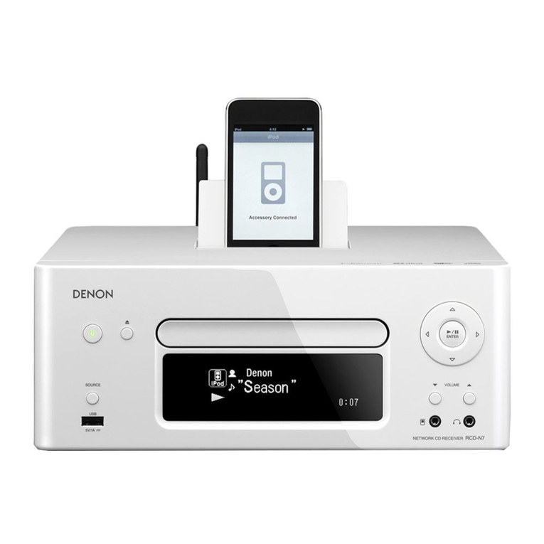
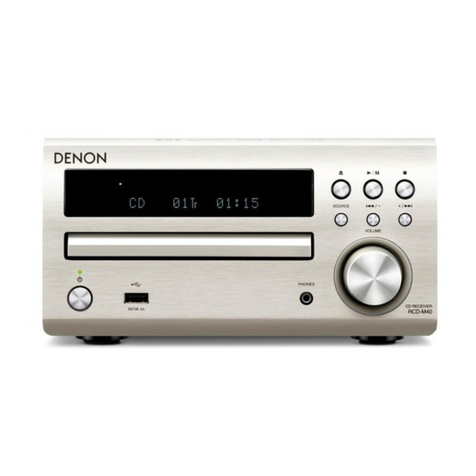
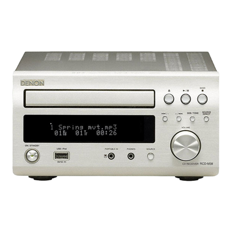
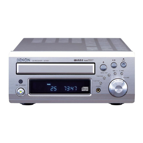
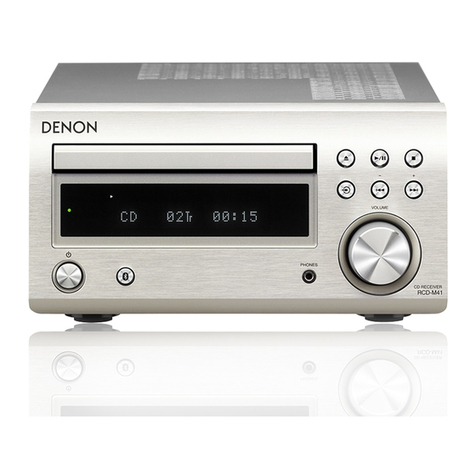
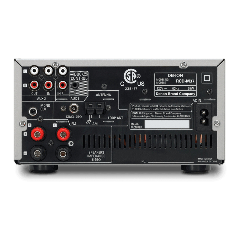
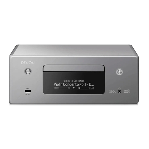
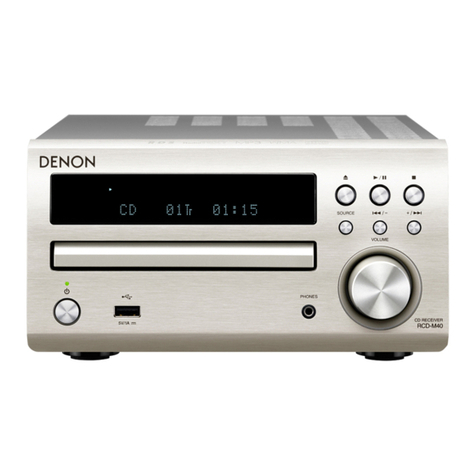
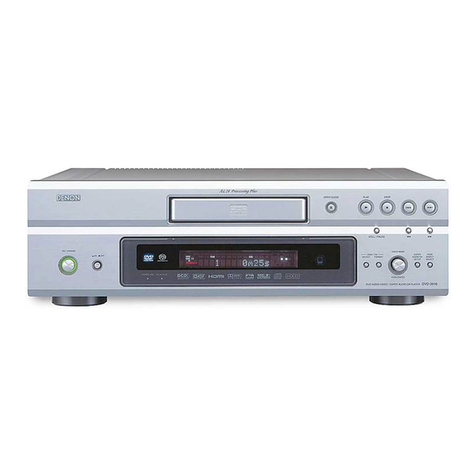
Denon RCD-CX1 User manual

Denon Brand Company, D&M Holdings lnc.
e
●For purposes of improvement, specifications and
design are subject to change without notice.
●Please use this service manual with referring to the
operating instructions without fail.
●Some illustrations using in this service manual are
slightly different from the actual set.
注 意
サービスをおこなう前に、このサービスマニュアルを
必ずお読みください。本機は、火災、感電、けがなど
に対する安全性を確保するために、さまざまな配慮を
おこなっており、また法的には「電気用品安全法」に
もとづき、所定の許可を得て製造されております。
従ってサービスをおこなう際は、これらの安全性が維
持されるよう、このサービスマニュアルに記載されて
いる注意事項を必ずお守りください。
●本機の仕様は性能改良のため、予告なく変更すること
があります。
●補修用性能部品の保有期間は、製造打切後 8 年です。
●修理の際は、必ず取扱説明書を参照の上、作業を行っ
てください。
●本文中に使用しているイラストは、説明の都合上現物
と多少異なる場合があります。
X0385 V.04 DE/CDM 0810
SERVICE MANUAL
STEREO CD RECEIVER
MODEL JP E3 E2 EK E2A E1C E1K EUT
RCD-CX1
333
Ver. 4
Please refer to the
MODIFICATION NOTICE.

2
RCD-CX1
Please heed the points listed below during servicing and inspection.
◎Heed the cautions!
Spots requiring particular attention when servicing, such
as the cabinet, parts, chassis, etc., have cautions indicated
on labels or seals. Be sure to heed these cautions and the
cautions indicated in the handling instructions.
◎Caution concerning electric shock!
(1) An AC voltage is impressed on this set, so touching in-
ternal metal parts when the set is energized could
cause electric shock. Take care to avoid electric shock,
by for example using an isolating transformer and
gloves when servicing while the set is energized, un-
plugging the power cord when replacing parts, etc.
(2)There are high voltage parts inside. Handle with extra
care when the set is energized.
◎Caution concerning disassembly and
assembly!
Though great care is taken when manufacturing parts from
sheet metal, there may in some rare cases be burrs on the
edges of parts which could cause injury if fingers are
moved across them. Use gloves to protect your hands.
◎Only use designated parts!
The set's parts have specific safety properties (fire resis-
tance, voltage resistance, etc.). For replacement parts, be
sure to use parts which have the same properties. In par-
ticular, for the important safety parts that are marked zon
wiring diagrams and parts lists, be sure to use the desig-
nated parts.
◎Be sure to mount parts and arrange
the wires as they were originally!
For safety reasons, some parts use tape, tubes or other in-
sulating materials, and some parts are mounted away from
the surface of printed circuit boards. Care is also taken with
the positions of the wires inside and clamps are used to
keep wires away from heating and high voltage parts, so
be sure to set everything back as it was originally.
◎Inspect for safety after servicing!
Check that all screws, parts and wires removed or discon-
nected for servicing have been put back in their original po-
sitions, inspect that no parts around the area that has been
serviced have been negatively affected, conduct an insu-
lation check on the external metal connectors and between
the blades of the power plug, and otherwise check that
safety is ensured.
(Insulation check procedure)
Unplug the power cord from the power outlet, disconnect
the antenna, plugs, etc., and turn the power switch on. Us-
ing a 500V insulation resistance tester, check that the in-
sulation resistance between the terminals of the power
plug and the externally exposed metal parts (antenna ter-
minal, headphones terminal, microphone terminal, input
terminal, etc.) is 1MΩor greater. If it is less, the set must
be inspected and repaired.
Concerning important safety
parts
Many of the electric and structural parts used in the set
have special safety properties. In most cases these prop-
erties are difficult to distinguish by sight, and using re-
placement parts with higher ratings (rated power and
withstand voltage) does not necessarily guarantee that
safety performance will be preserved. Parts with safety
properties are indicated as shown below on the wiring dia-
grams and parts lists is this service manual. Be sure to re-
place them with parts with the designated part number.
(1) Schematic diagrams ... Indicated by the zmark.
(2) Parts lists ... Indicated by the zmark.
Using parts other than the designated
parts could result in electric shock, fires or
other dangerous situations.
SAFETY PRECAUTIONS
The following check should be performed for the continued protection of the customer and service technician.
LEAKAGE CURRENT CHECK
Before returning the unit to the customer, make sure you make either (1) a leakage current check or (2) a line to chassis
resistance check. If the leakage current exceeds 0.5 milliamps, or if the resistance from chassis to either side of the
power cord is less than 460 kohms, the unit is defective.
LASER RADIATION
Caution - Class 1M visible and invisible laser radiation when open.
Do not view directly with optical instruments.
CAUTION
CAUTION
3
RCD-CX1
サービス、点検時にはつぎのことにご注意願います。
◎注意事項をお守りください!
サービスのとき特に注意を必要とする個所については
キャビネット、部品、シャーシなどにラベルや捺印で注意
事項を表示しています。これらの注意書きおよび取扱説明
書などの注意事項を必ずお守りください。
◎感電に注意!
(1) このセットは、交流電圧が印加されていますので通電
時に内部金属部に触れると感電することがあります。
従って通電サービス時には、絶縁トランスの使用や手
袋の着用、部品交換には、電源プラグを抜くなどして
感電にご注意ください。
(2) 内部には高電圧の部分がありますので、通電時の取扱
には十分ご注意ください。
◎分解、組み立て作業時のご注意!
板金部品の端面の『バリ』は、部品製造時に充分管理をし
ておりますが、板金端面は鋭利となっている箇所が有りま
すので、部品端面に触れたまま指を動かすとまれに怪我を
する場合がありますので十分注意して作業して下さい。手
の保護のために手袋を着用してください。
◎指定部品の使用!
セットの部品は難燃性や耐電圧など安全上の特性を持っ
たものとなっています。従って交換部品は、使用されてい
たものと同じ特性の部品を使用してください。特に配線
図、部品表にz印で指定されている安全上重要な部品は
必ず指定のものをご使用ください。
◎部品の取付けや配線の引きまわしは、
元どおりに!
安全上、テープやチューブなどの絶縁材料を使用したり、
プリント基板から浮かして取付けた部品があります。また
内部配線は引きまわしやクランパーによって発熱部品や
高圧部品に接近しないように配慮されていますので、これ
らは必ず元どおりにしてください。
◎サービス後は安全点検を!
サービスのために取り外したねじ、部品、配線などが元ど
おりになっているか、またサービスした個所の周辺を劣化
させてしまったところがないかなどを点検し、外部金属端
子部と、電源プラグの刃の間の絶縁チェックをおこなうな
ど、安全性が確保されていることを確認してください。
(絶縁チェックの方法)
電源コンセントから電源プラグを抜き、アンテナやプラグ
などを外し、電源スイッチを入れます。500V 絶縁抵抗計
を用いて、電源プラグのそれぞれの端子と外部露出金属部
[アンテナ端子、ヘッドホン端子、マイク端子、入力端子
など]との間で、絶縁抵抗値が1 MΩ 以上であることを
確認してください。この値以下のときはセットの点検修理
が必要です。
安全上重要な部品について
本機に使用している多くの電気部品、および機構部品は安
全上、特別な特性を持っています。この特性はほとんどの
場合、外観では判別つきにくく、またもとの部品より高い
定格(定格電力、耐圧)を持ったものを使用しても安全性
が維持されるとは、限りません。安全上の特性を持った部
品は、このサービスマニュアルの配線図、部品表につぎの
ように表示していますので必ず指定されている部品番号
のものを使用願います。
(1) 配線図…zマークで表示しています。
(2) 部品表…zマークで表示しています。
指定された部品と異なるものを使用した場
合には、感電、火災などの危険を生じる恐
れがあります。
注 意
注 意

4
RCD-CX1
DIMENSION
138.8130.4
158 300.7 25.5max
220
220
48 212
300
10 100
40
40
40

5
RCD-CX1
ワイヤー整形図
調整や部品の交換等により、ワイヤー類の結束をはずした
り移動させた場合には、それらの作業が完了した時点でワ
イヤーの整形をおこなってください。正しく整形されてい
ないとノイズ発生の原因となることがあります。
上面からみたワイヤー整形
WIRE ARRANGEMENT
If wire bundles are untied or moved to perform adjustment or
parts replacement etc., be sure to rearrange them neatly as
they were originally bundled or placed afterward.
Otherwise, incorrect arrangement can be a cause of noise
generation.
Wire arrangement viewed from the top
Back Panel side
Front Panel side

6
RCD-CX1
サービス時の注意事項
1. 初期化について
マイコンやマイコン周辺部品、メイン基板、メカを交換
した場合は、初期化をおこなってください。
1. 電源コードを抜きます。
2. "+/9" ボタンと "SOURCE" ボタンを同時に押しなが
ら、電源コードをコンセントへ接続します。
3. "ON/STANDBYLED"が赤色点滅したのを確認後、2つ
のボタンから指を離します。
4. FL 管に "RESET" と表示されます。
5. その後、FL 管の "RESET" 表示が消え、"ON/STANDBY
LED"の赤色点滅が赤色点灯へ移行してから電源コード
を抜きます。
*マイコンが初期化されます。
2. バージョン表示方法
1. 電源コードを抜きます。
2. " /
13"ボタンと"8/-" ボタンを同時に押しながら、
電源コードをコンセントへ接続します。"Ver.Disp" が
FL 管に表示されます。次にシステムマイコンのバー
ジョンが FL 管に表示されます。
3. その後、"+/9" ボタンを押すと、下記の情報が FL 管
に表示されます。
<表示順序>
B/E のバージョン→ B/E の Makeday → iPodDock の
バージョン→ EEPROM のチェックサム確認結果(b1
参照)→ B/E との通信結果(b2 参照)→ FL 管の全点
灯と全消灯を 1 秒間隔でおこないます。
b1 EEPROM. のチェック確認結果
"EEPOK":正常
"EEPErr1":Tuner/Timer 関連チェックサムエラー
"EEPErr2":Amp 関連チェックサムエラー
"EEPErr3":最終 Line1,2selectチェックサムエラー
b2 B/E との通信結果
"BEOK":正常
"BEErr":通信不可
注意 :・上記 3 の状態にならない場合は、もう一度操作 1
からやり直してください。
・初期化を行うとお客様が設定した内容が工場出
荷状態に戻りますので、あらかじめ設定内容を
控えておき初期化後再設定してください。
CAUTION IN SERVICING
1. Initializing
Initialization should be performed when the µcom, periph-
eral parts of µcom, MAIN P.W.B. unit and Mecha are re-
placed.
1. Unplug the power cord.
2. Plug the power cord into a power outlet while pressing
“+/9” button and “SOURCE” button simultaneously.
3. Check that the "ON/STANDBY LED" is red flashes and
release your fingers from the 2 buttons.
4. "RESET" is displayed on the FL tube.
5. Now, "RESET" display of FL tube turns off and red flash
of "ON/STANDBY LED" switches to red lighting, and
power supply code is unplugged.
*The microprocessor will be initialized.
2. Version display
1. Unplug the power cord.
2. When plug the power cord into a power outlet while
pressing “ /
13” button and “8/-” button simulta-
neously. "Ver.Disp" is displayed on the FL tube. Next,
the version of the system μcom is displayed on FL tube.
3. Now, press the "+/9" button, following information is
displayed on the FL tube.
<Display Order>
VersionofB/E→Make day of B/E→Version ofiPod Dock
→Checksum check result of EEP ROM (Refere to b1)
→Communication result with B/E (Refere to b2) →The
entire FL tube is flashing with an interval of about 1 sec-
ond.
b1 Checksum check result of EEP ROM
"EEP OK" : normal
"EEP Err1" : Tuner/Timer-related checksum error
"EEP Err2" : Amp-related checksum error
"EEP Err3" : Last Line1,2 select checksum error
b2 Communication result with B/E
"BE OK" : normal
"BE Err" : Communication error
Note:・If step 3 does not work, start over from step 1.
・All user settings will be lost and this factory setting
will be recovered when this initialization mode.
So make sure to m+emorize your setting for re-
storing after the initialization.
1/3
8/-
+/9
SOURCEON/STANDBY LED
s

7
RCD-CX1
DISASSEMBLY
• Disassemble in order of the arrow of the figure of following flow.
下記フロー図の矢印の順番にはずしてください。
• In the case of the re-assembling, assemble it in order of the reverse of the following flow.
再組み立ての場合は、下記のフローの逆の順番に組立ててください
• In the case of the re-assembling, observe "attention of assembling" it.
再組み立ての場合は、「組立のご注意」を遵守してください。
TOP PANEL
SIDE PANE
L
TOP ANGLE
SW POWER UNIT FRONT PANEL SUB ASS
Y
Refer to "DISASSEMBLY Refer to "DISASSEMBLY
2.SW POWER UNIT" 1.FRONT PANEL SUB ASSY"
and "EXPLODED VIEW" and "EXPLODED VIEW"
SW POWER UNIT DISPLAY UNIT
(Ref. No. of EXPLODED VIEW : 1) (Ref. No. of EXPLODED VIEW : 3-1)
VOLUME UNIT SUB ASSY
SHIELD BRACKE
T
(Ref. No. of EXPLODED VIEW : 3-2)
POWER SW UNIT
(Ref. No. of EXPLODED VIEW : 3-3)
FRONT PANEL SUB ASS
Y
BACK PANEL ASS
Y
HEAD PHONE UNIT
Refer to "DISASSEMBLY Refer to "DISASSEMBLY (Ref. No. of EXPLODED VIEW : 3-8)
4.FRONT PANEL SUB ASSY" 3.BACK PANEL ASSY"
and "EXPLODED VIEW" and "EXPLODED VIEW"
DISPLAY UNIT FAN
(Ref. No. of EXPLODED VIEW : 3-1) (Ref. No. of EXPLODED VIEW : 3-2)
VOLUME UNIT SUB ASSY AM FM TUNER
(Ref. No. of EXPLODED VIEW : 3-2) (Ref. No. of EXPLODED VIEW : 3-2)
POWER SW UNIT AC INLET SUB ASSY
(Ref. No. of EXPLODED VIEW : 3-3) (Ref. No. of EXPLODED VIEW : 3-2)
HEAD PHONE UNIT SP TERMINAL UNIT
(Ref. No. of EXPLODED VIEW : 3-8) (Ref. No. of EXPLODED VIEW : 3-5)
TOP PANEL BRACKE
T
FRONT ANGLE
SACD MECHA ASS
Y
Refer to "DISASSEMBLY
5.SACD MECHA ASSY"
and "EXPLODED VIEW"
SACD MECHA UNIT
(Ref. No. of EXPLODED VIEW : 2-3)
MAIN UNIT SUB ASS
Y
Refer to "DISASSEMBLY
6.MAIN UNIT SUB ASSY"
and "EXPLODED VIEW"
MAIN UNIT SUB ASSY
(Ref. No. of EXPLODED VIEW : 2-2)

8
RCD-CX1
Front side
Picture B
Picture A
Picture C Picture D
Top view
The viewpoint of each photograph
(photography direction)
各図の視点(撮影方向)

9
RCD-CX1
1. FRONT PANEL SUB ASSY
(1) Remove the screws. ( ねじをはずす。)
(2) Disconnect the connector wire and FFC cable.(コネクタワイヤーと FFC ケーブルをはずす。)
Please refer to "EXPLODED VIEW" for the disassembly method of each P.W.B included in FRONT PANEL SUB ASSY.
FRONTPANELSUBASSY の各基板のはずしかたは "EXPLODEDVIEW" を参照してください。
Proceeding (手順) : TOP PANEL →SIDE PANEL →FRONT PANEL SUB ASSY
Bottom view
Top view
FFC CABLE
Picture A
CY051

10
RCD-CX1
2. SW POWER UNIT
(1) Remove the screws. ( ねじをはずす。)
(2) Disconnect the connector wires and boards.(コネクタワイヤーとコネクタボードをはずす。)
(3) Remove the screws.(ねじをはずす。)
Proceeding (手順) : TOP PANEL →SIDE PANEL
→TOP ANGLE →SW POWER UNIT →SHIELD BRACKET
Picture C
TOP ANGLE
Top view
CW021
CW021
CW021 CW021
Top view

11
RCD-CX1
(4) Remove the screws.(ねじをはずす。)
3. BACK PANEL ASSY
(1) Disconnect the connector wire.(コネクタワイヤーをはずす。)
Picture C
SHIELD BRACKET
Top v i e w
Proceeding (手順) : TOP PANEL →SIDE PANEL
→TOP ANGLE →SW POWER UNIT →SHIELD BRACKET
→BACK PANEL ASSY
CX022
Top v i e w
CX023 FFC CABLE
CORD HOLDER : Loose

12
RCD-CX1
(2) Remove the screws.(ねじをはずす。)
(3) Disconnect the connector wire.(コネクタワイヤーをはずす。)
Please refer to "EXPLODED VIEW" for the disassembly method of each P.W.B included in BACK PANEL ASSY.
BACKPANELASSY の各基板のはずしかたは "EXPLODEDVIEW" を参照してください。
Picture B
ً
CW021
Top view

13
RCD-CX1
4. FRONT PANEL SUB ASSY
(1) Remove the screws. ( ねじをはずす。)
(2) Disconnect the connector wire and FFC cable.(コネクタワイヤーと FFC ケーブルをはずす。)
Proceeding (手順) : TOP PANEL →SIDE PANEL
→TOP ANGLE →SW POWER UNIT →SHIELD BRACKET
→FRONT PANEL SUB ASSY →TOP PANEL BRACKET
→FRONT ANGLE
Bottom view
Top view
CY051
Top v i e w
FFC CABLE

14
RCD-CX1
(3) Remove the screws.(ねじをはずす。)
5. SACD MECHA ASSY
(1) Disconnect the connector wires. ( コネクタワイヤーをはずす。)
Picture D
FRONT ANGLE
TOP PANEL BRACKET
Proceeding (手順) : TOP PANEL →SIDE PANEL
→TOP ANGLE →SW POWER UNIT →SHIELD BRACKET
→FRONT PANEL SUB ASSY →TOP PANEL BRACKET
→FRONT ANGLE →SACD MECHA ASSY
FFC CABLE
Top v i e w
CY091
CORD HOLDER : Loose

15
RCD-CX1
(2) Remove the screw.(ねじをはずす。)
6. MAIN UNIT SUB ASSY
Please refer to "EXPLODED VIEW" for the disassembly method of MAIN UNIT SUB ASSY.
MAINUNITSUBASSY のはずしかたは "EXPLODEDVIEW" を参照してください。
Top view
Top view
Proceeding (手順) : TOP PANEL →SIDE PANEL
→TOP ANGLE →SW POWER UNIT →SHIELD BRACKET
→FRONT PANEL SUB ASSY →TOP ANGLE BRACKET
→FRONT ANGLE →SACD MECHA ASSY
→MAIN UNIT SUB ASSY

16
RCD-CX1
LOADERPANELの位置調整
この調整は、ローダーパネルの周囲の隙間(上、下、左、
右)が不均一なときの修理の場合と、修理の際に取り外し
たメカを再び取り付ける場合におこなってください。
<準備>
・ まず、電源を ONにし、TRAYの OPEN/CLOTHを1回お
こない、電源を OFFにする。
・ 現状のそれぞれの隙間を確認します。
・ 8U-210025SWPOWERUNIT、SHIELDBRACKETを外す。
・ メカを固定しているネジ4本を外す。
AJUSTING THE POSITION OF THE
LOADER PANEL
Perform this adjustment when repairing for uneven gaps
around the loader panel (top, bottom, left and right) and when
remounting mechanisms removed when making repairs.
<Preparations>
• First turn on the power, open and close the tray once,
then turn the power off.
• Check the various actual gaps.
• Remove the 8U-210025 SW power unit and shield
bracket.
• Remove the four screws fixing the mechanism in place.
メカ
Mechanism
左の隙間
右の隙間
上の隙間
下の隙間
Ajusting the left gaps Ajusting the top gaps

17
RCD-CX1
1.隙間の調整
1.1. 左右の隙間の確認
(1) メカを前方につきあてながら、左右の隙間が同じに
なるように調整する。(左右目視)
1.2. 上下の隙間の確認
(1) 六角レンチを使って左右の3*8セットスクリュー
を回し、左右それぞれのトレイの上下の隙間を調整
する。(時計方向に回すと上の隙間が狭くなります。)
(2) ▲印のネジ2本でメカを固定する。
(3) ※印のネジ2本でメカを固定する。
[注意]
必ず▲印を先におこなうこと。
2.再組立て
8U-210025SWPOWERUNIT,SHIELDBRACKET を取り付けて
ください。
3.最終確認
作業終了後、電源を ON にし TRAY の OPEN/CLOTH を1回
おこない、隙間の確認をおこなってください。
1.Adjusting the gaps
1.1. Adjusting the left and right gaps
(1) With the mechanism pressing against the front, adjust
so that there is no gap on the left and right.
.
1.2. Adjusting the top and bottom gaps
(1) Using a hexagonal wrench, turn the 3*8 set screws on
the left and right to adjust the top and bottoms gaps of
the left and right trays.
(2) Fasten the mechanism using the two screws marked
d.
(3) Fasten the mechanism using the two screws marked
b.
GNOTEH
Be sure to fasten the screws marked d first.
2.Reassembly
Mount the 8U-210025 SW power unit and shield bracket.
3.Final check
After completing the operations, turn on the power and open
and close the tray once to check the gap.
メカ
Mechanism

18
RCD-CX1
光ピックアップの故障診断とトラバー
スユニットの交換
次の順序で故障診断をおこなってください。
レーザー駆動電流 Iop 値が初期値の 1.5 倍以上になってい
る場合は光ピックアップ交換の目安となります。
レーザー駆動電流初期値は、次ページ "Iop 値の確認方法 "
で確認できます。
ピックアップ交換の場合は、トラバースユニット単位での
交換となります。メカの調整は不要です。
ディスクを読み込まない
スムーズに再生しない、等
レーザー駆動電流 Iop 値の確認
HF 波形の確認(WAVEFORMS参照)
トラバースユニット交換
交換後にレーザー電流値の記憶
現在値が初期値の
1.5 倍になっている
DIAGNOSTICSOFOPTICALPICKUP
AND REPLACING TRAVERSE UNIT
Make failure diagnostics of the Optical Pickup as follows.
If the laser drive current (Iop) becomes more than 1.5 times
of the initial value, the Optical Pickup should be replaced.
The laser drive current initial value is checked by "Iop
checked Method" of next page.
IncaseofreplacingthePickup, change the whole part of the
Traverse Unit.
No mechanical adjustment is necessary after the replace-
ment.
レーザー駆動電流初期値 :
Laser drive current initial value:
FLDisplay(Thedisplaypartof8digits)
12345678
T2 3 ―mmmm
FLDisplay(Thedisplaypartof8digits)
12345678
T2 1 ―mmmm
DVD:
CD:
Disc no read, unsteady playback, etc.
Laser drive current (Iop) check
HF wave form check
(Refer to WAVE FORMS)
Traverse Unit replacing
Laser current (Iop) memorizing after replacement
Present value exceeds the ini-
tial value by 1.5 times

19
RCD-CX1
1. Iop 値の確認方法
レーザー駆動電流を確認する場合は、テストモードの
レーザー ON/OFF(CD/DVD) モードを選択して、DVD
レーザーまたは CD レーザーの lop 値を確認します。
(詳細は 16 ページ、テストモード参照)
1.1. DVD レーザー電流確認
(1) レーザー電流値を表示する場合 8または 9ボ
タンを押し、"T24" を選択します。
(2) 現在の lop 値 (nnnn) を確認します。
( −:消灯、DVD レーザー、現在値:nn.nn[mA])
1.2. CD レーザー電流確認
(1) レーザー電流値を表示する場合は 8または 9
ボタンを押し、"T22" を選択します。
(2) 現在の lop 値 (nnnn) を確認します。
( −:消灯、CD レーザー、現在値:nn.nn[mA])
2. レーザーピックアップの取扱注意
レーザーダイオードの破壊防止。
光素子ユニットを交換するときは、以下を遵守してくだ
さい。
(1) 光素子ユニットの接続ケーブルをはずすときは、静
電対策を行ったデスク上で作業してください。
(2) 作業者は、リストストラップを使用してください。
(3) レーザーダイオードの破壊防止のため、24PFFC ケー
ブルをはずす前にランドを半田付けショートしてく
ださい。
(4) 光素子ユニットのコネクタ部に触れないでください。
3. レーザーピックアップ ( トラバースユ
ニット ) の交換
Iop( レーザー駆動電流)をチェックします。
現在の Iop 値が初期値の 150%を越えている場合、トラ
バースユニット(レーザーピックアップ)を交換してく
ださい。
FL 管の表示 (8 桁の表示部 )
12345678
T24―nnnn
FL 管の表示 (8 桁の表示部 )
12345678
T22―nnnn
1. Iop checked Method
Select the laser ON/OFF (CD/DVD) mode of the test
mode, and check the lop value of DVD laser or CD laser.
(See page 16 for test mode.)
1.1. DVD laser current check
(1) Press the 8or 9button to display the laser cur-
rent value, and then select “T24”.
(2) Check the current value of Iop (nnnn).
(−: Off, DVD laser, Initial value: Current value: nn.nn [mA])
1.2. CD Laser current check
(1) Press the 8or 9button to display the laser cur-
rent value, and then select “T22”.
(2) Check the current value of Iop (nnnn).
(−: Off, CD laser, Initial value: Current value: nn.nn [mA])
2. Note for Handling the Laser Pick-Up
The protection for the damage of laser diode.
If you want to change the optical device unit from any oth-
er units, you must keep the following.
(1) It should be done at the desk already took measures
the static electricity in care of removing the OPU's (Op-
tical device unit) connector cable.
(2) Workers should be put on the "Earth Band".
(3) It should be done to add the solder to the short land to
prevent the broken Laser diode before removing the
24P FFC cable.
(4) Don't touch OPU's connector parts carelessly.
3. Replacement of the Laser Pick-up
(Traverse Unit)
Check the Iop (Laser drive current)
If the present Iop (current) value exceeds.+150% of the
initialvalue,replacetheTraverseunit(LaserPick-up)with
a new one.
FLDisplay(Thedisplaypartof8digits)
12345678
T24―nnnn
FLDisplay(Thedisplaypartof8digits)
12345678
T22―nnnn

20
RCD-CX1
4. レーザー電流初期値の書き換え方法
4.1. 現在のレーザー電流値を保存する場合:DVD
(1) "T24" 現在値を選択します。
(2) /
13ボタンを 5 秒以上を押し、"SAVE?" を表示します。
(3) 8または 9ボタンを押し "T23" を選択します。
(4) /
13ボタン押すと、"T23" 現在値を保存し、"OK?" 表
示後、"T23" 保存値の表示へ戻ります。
(5) /
25ボタンを押すと、"T23" 現在値を保存せず、
"T24" 現在値の表示へ戻ります。
4.2. 現在のレーザー電流値を保存する場合:CD
(1) "T22" 現在値を表示します。
(2) /
13ボタンを 5 秒以上を押し、"SAVE?" を表示します。
(3) 8または 9ボタンを押し "T21" を選択します。
(4) /
13ボタン押すと、"T21" 現在値を保存し、"OK?" 表示
後、"T21" 保存値の表示へ戻ります。
(5) /
25ボタンを押すと、"T21" 現在値を保存せず、
"T22" 現在値の表示へ戻ります。
FL 管の表示 (8 桁の表示部 )
12345678
T24―nnnn
FL 管の表示 (8 桁の表示部 )
12345678
T2 4 S A V E ?
FL 管の表示 (8 桁の表示部 )
12345678
T2 3 ―mmmm
FL 管の表示 (8 桁の表示部 )
12345678
T2 3 ――O K !
FL 管の表示 (8 桁の表示部 )
12345678
T22―nnnn
FL 管の表示 (8 桁の表示部 )
12345678
T2 2 S A V E ?
FL 管の表示 (8 桁の表示部 )
12345678
T2 1 ―mmmm
FL 管の表示 (8 桁の表示部 )
12345678
T2 1 ――O K !
4. Rewriting the default value of the laser
current
4.1. Store the current value of the laser current :
DVD
(1) Current value “T24” is selected.
(2) Press the /
13button for at least 5 seconds, and
"SAVE?" is displayed.
(3) Press the 8or 9button to select the “T23”.
(4) Press the /
13button and store the current value
"T23". After “OK?” is displayed, stored value “T23” is
displayed.
(5) Pressthe /
25button to displaythecurrentvalue“T24”
without storing the current value “T23”.
4.2. Store the current value of the laser current : CD
(1) Current value “T22” is selected.
(2) Press the /
13button for at least 5 seconds, and
"SAVE?" is displayed.
(3) Press the 8or 9button to select the “T21”.
(4) Press the /
13button and store the current value
"T21". After “OK?” is displayed, stored value “T21” is
displayed.
(5) Pressthe /
25button to displaythecurrentvalue“T22”
without storing the current value “T21”.
FLDisplay(Thedisplaypartof8digits)
12345678
T24―nnnn
FLDisplay(Thedisplaypartof8digits)
12345678
T2 4 S A V E ?
FLDisplay(Thedisplaypartof8digits)
12345678
T23 ―mmmm
FLDisplay(Thedisplaypartof8digits)
12345678
T2 3 ――O K !
FLDisplay(Thedisplaypartof8digits)
12345678
T22―nnnn
FLDisplay(Thedisplaypartof8digits)
12345678
T2 2 S A V E ?
FLDisplay(Thedisplaypartof8digits)
12345678
T21 ―mmmm
FLDisplay(Thedisplaypartof8digits)
12345678
T2 1 ――O K !
Other manuals for RCD-CX1
3
Table of contents
Other Denon Car Receiver manuals

Denon
Denon RCD-M38 User manual

Denon
Denon RCD-M40 User manual

Denon
Denon RCD-CX1 User manual

Denon
Denon ceol RCD-N12DAB User manual

Denon
Denon RCD-N7 User manual

Denon
Denon D-107 User manual

Denon
Denon RCD-M41 User manual

Denon
Denon RCD-M39 User manual

Denon
Denon RCD-M33 User manual

Denon
Denon RCD-M38 User manual

Denon
Denon CEOL RCD-N8 User manual

Denon
Denon D-T1 User manual

Denon
Denon RCD-M35DAB User manual

Denon
Denon RCD-M39 User manual

Denon
Denon D RCD-M37 User manual

Denon
Denon RCD-M40 User manual

Denon
Denon RCD-M39 User manual

Denon
Denon RCD-CX1 User manual

Denon
Denon D-T1 User manual

Denon
Denon DM40SBK User manual