7
DVD-5910/DVD-A1XV
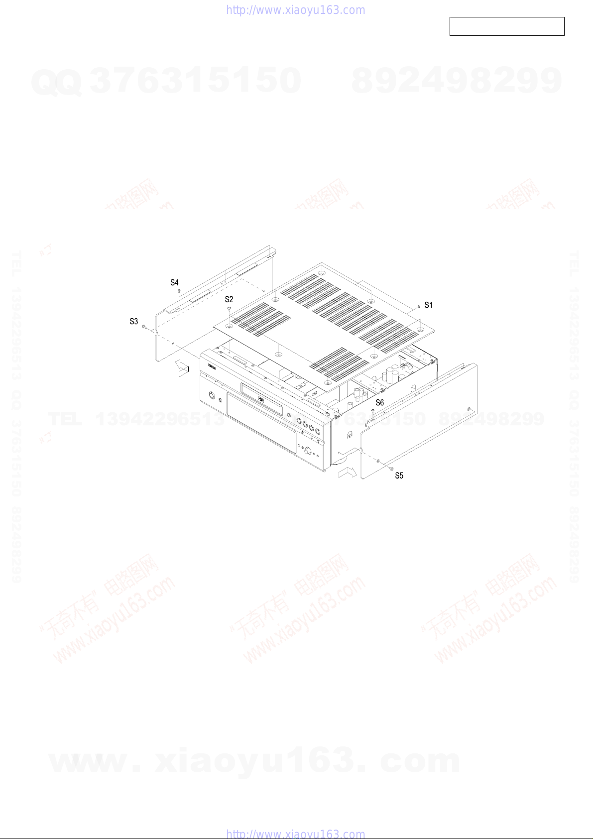
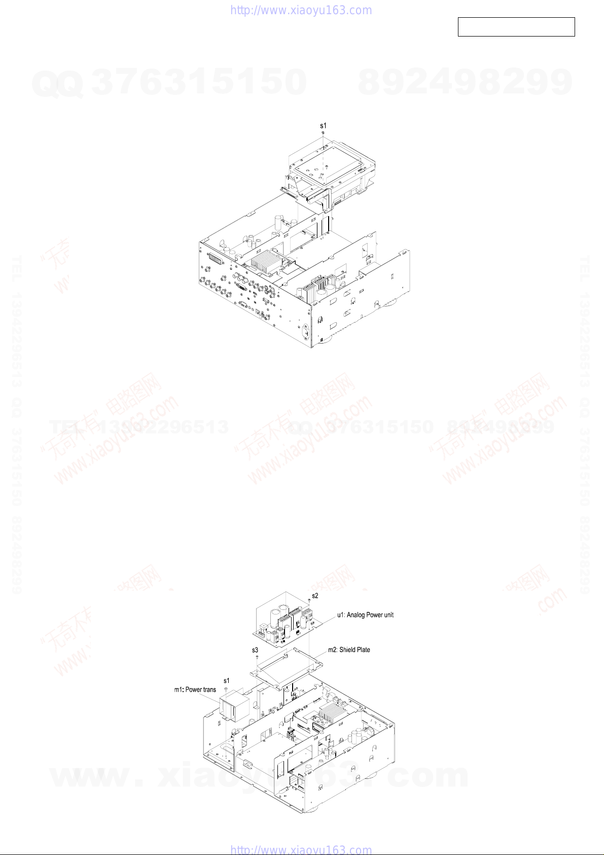
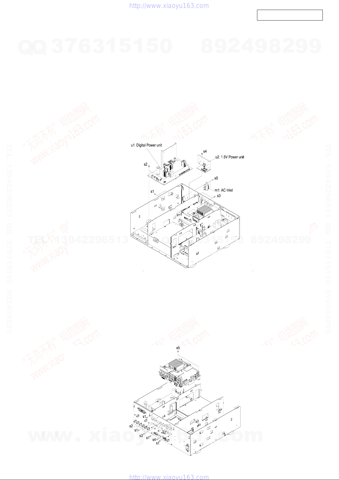
5. Digital Power unit
5.1. Digital Power unit
(1) Remove 2 side screws (s1).
(2) Disconnect the wires [CX024] [CX081] [CX101] [CX121]
[CX063] connecting Digital Power unit.
(3) Remove 4 top screws (s2), then detach the Digital Power
unit (u1).
5.2. 1.5V Power unit
(1) Remove 2 rear screws (s3).
(2) Disconnect the wire [CX059] connecting 1.5V Power unit.
(3) Remove 1 top screw (s4), then detach the 1.5V Power
unit (u2).
(4) Remove 2 rear screws (s5), then detach the AC Inlet
(m1).
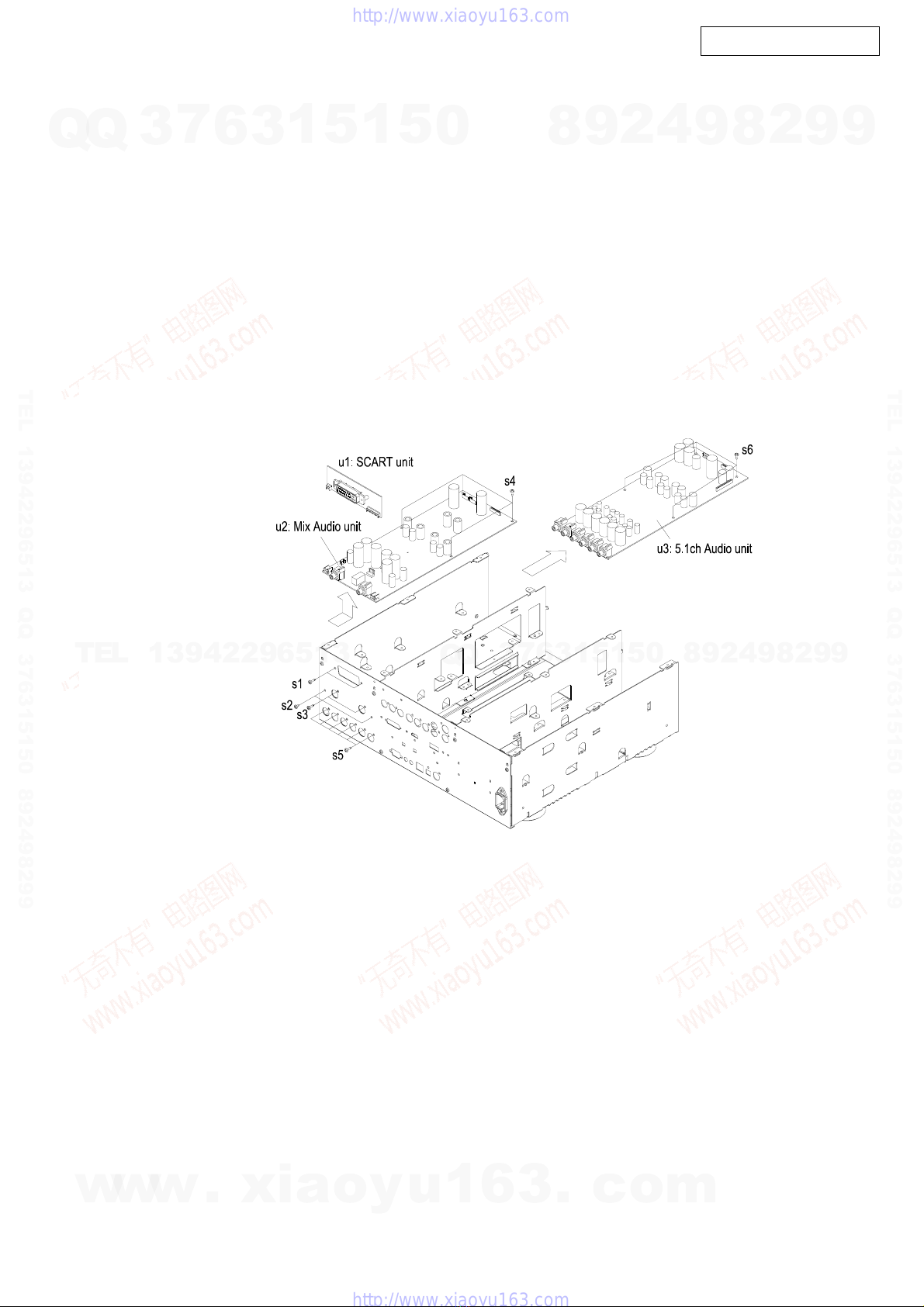
6. Video Unit
(1) Disconnect the wire [CY059] connecting the I/P unit, the
FFC [CY331] and the wires [CY081] [CX031] [CX102]
connecting the Video2 unit, the FFC [CX174] connecting
the Video1 unit.
(Note: The wire [CX102] only Europe & China model.)
(2) Remove 9 screws (s1), 6 screws (s2), 2 screws (s3) and
1 screw (s4) on the rear side.
(Note: The 1 screw of s4 provide only Japan model.)
(3) Remove 2 top screws (s5), then detach the Video unit.
5. DigitalPowerunit
5.1. DigitalPowerunit
(1) 側面側からネジ s1 を 2 本をはずします。
(2) DigitalPowerunit からワイヤー
[CX024][CX081][CX101][CX121][CX063] をはずします。
(3) 天面側から s2 のネジ 4 本をはずし、u1:DigitalPower
unit をはずします。
5.2. 1.5VPowerunit
(1) 背面側から s3 のネジ 2 本をはずします。
(2) 1.5VPowerunit からワイヤー [CX059] をはずします。
(3) 天面側から s4 のネジ 1 本をはずし、u2:1.5VPowerunit
をはずします。
(4) 背面側から s5 のネジ 2 本をはずし、m1:ACInlet をは
ずします。
6. Videounit
(1) I/Punit からワイヤー [CY059]、Video2unit から
FFC[CY331] とワイヤー [CY081],[CX031]、(E2、E1C 仕
向けは、さらに [CX102])、Video1unit から FFC[CX174]
をはずします。
(2) 背面側からネジ s1 を 9 本、ネジ s2 を 6 本、ネジ s3 を
2 本、( 日本向けのみ、ネジ s4 を 1 本 ) はずします。
(3) 天面側からネジ s5 を 2 本はずし、Videounit をはずし
ます。
w
w
w
.
x
i
a
o
y
u
1
6
3
.
c
o
m
Q
Q
3
7
6
3
1
5
1
5
0
9
9
2
8
9
4
2
9
8
T
E
L
1
3
9
4
2
2
9
6
5
1
3
9
9
2
8
9
4
2
9
8
0
5
1
5
1
3
6
7
3
Q
Q
TEL 13942296513 QQ 376315150 892498299
TEL 13942296513 QQ 376315150 892498299
http://www.xiaoyu163.com
http://www.xiaoyu163.com