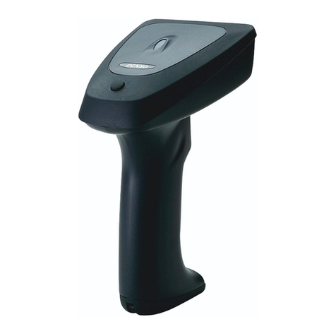
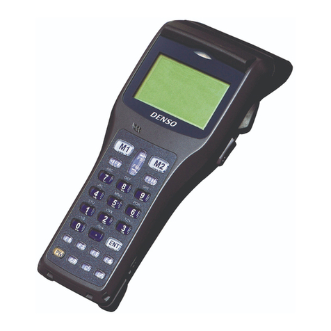
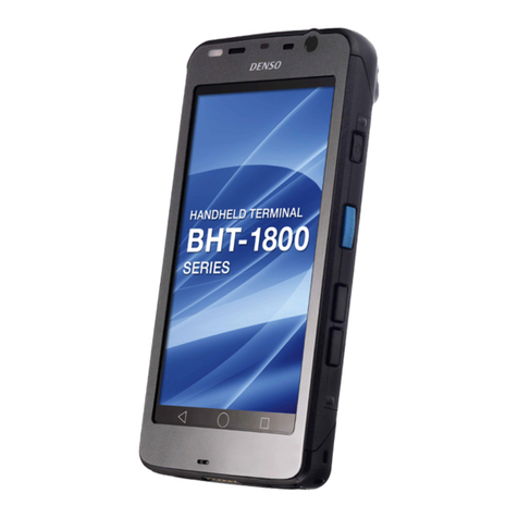
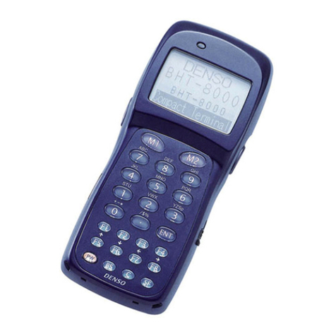
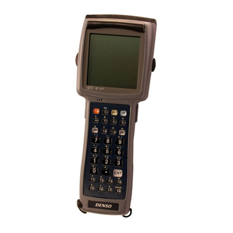
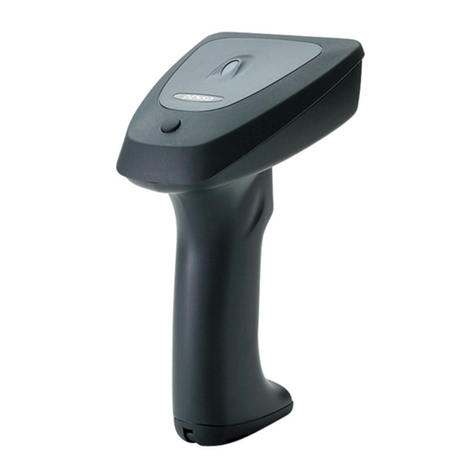
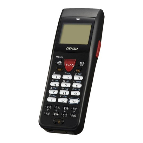
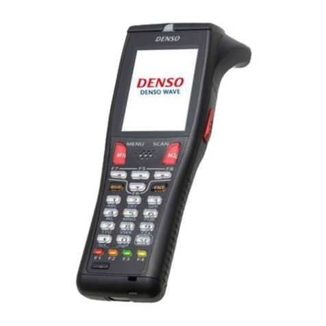
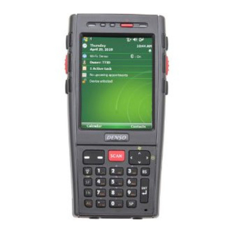
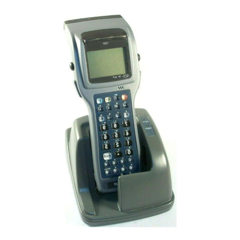
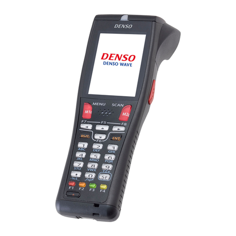
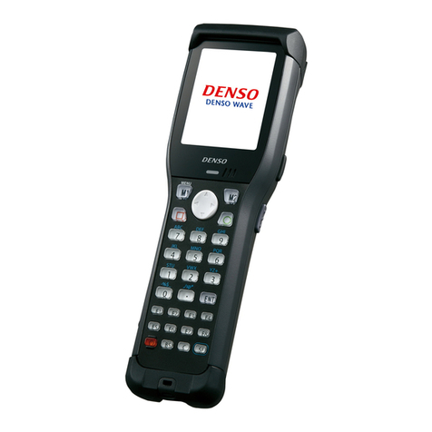
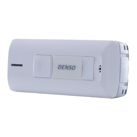
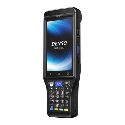
Denso BHT-700-CE User manual

A
PI Reference Manual
Barcode Handy Terminal
BHT-70
0
-C
E

Copyright © DENSO WAVE INCORPORATED, 2007
All rights reserved. No part of this publication may be reproduced in any form or by any means without
permission in writing from the publisher.
Specifications are subject to change without prior notice.
All products and company names mentioned in this manual are trademarks or registered trademarks of their
respective holders.

Contents
Chapter 1. Software Requirements for the BHT-700 ...................................................................................... 1
1.1. Operating System (OS) on the BHT-700.......................................................................................... 1
1.2. Application Development Software on the PC.................................................................................. 1
1.2.1. Application Development Tool ...................................................................................................... 1
1.2.2. Software Development Kit ............................................................................................................ 1
Chapter 2. Application Development Environment ......................................................................................... 2
2.1. Required Hardware (PC to be used for application development) ................................................... 2
2.2. Required Software ........................................................................................................................... 2
2.3. Installation ........................................................................................................................................ 2
Chapter 3. Output to the LCD Screen............................................................................................................. 3
3.1. Screen Fonts.................................................................................................................................... 3
3.2. Screen Rotation ............................................................................................................................... 3
3.2.1. Setting the Screen Rotation Control Key ...................................................................................... 3
3.3. Setting the Screen Rotation Angle ................................................................................................... 4
Chapter 4. Backlight Control........................................................................................................................... 5
4.1. Outline.............................................................................................................................................. 5
4.2. Setting the Backlight Function On/Off Key ....................................................................................... 5
4.3. Setting the Backlight Illumination Time............................................................................................. 6
4.4. Setting the Backlight Brightness and Power Saving Mode............................................................... 6
4.5. Controlling the Backlight with the Backlight Control Key .................................................................. 7
4.6. Controlling the Backlight with the Backlight Control Function........................................................... 8
4.7. Key Backlight ................................................................................................................................... 9
Chapter 5. Beeper and Vibrator Control ....................................................................................................... 10
5.1. Outline............................................................................................................................................ 10
5.2. Setting the Beeper/Vibrator ............................................................................................................ 11
5.3. Starting/Stopping the Beeper/Vibrator............................................................................................ 12
5.4. Priority Orders between Events that Activate the Beeper/Vibrator ................................................. 12
5.5. Beeper Volume Patterns ................................................................................................................ 12
Chapter 6. Keys and Trigger Switch Control ................................................................................................ 13
6.1. Outline............................................................................................................................................ 13
6.2. Setting the Keys and Trigger Switch .............................................................................................. 14
6.3. Shift Key Operation Mode .............................................................................................................. 15
6.4. Magic Key Control.......................................................................................................................... 15
6.5. Assigning a User-Defined Key Code to the Magic Keys ................................................................ 16
6.5.1. Assignment Method .................................................................................................................... 16
6.5.2. User-Defined Code Settings File (MKeyDef.txt).......................................................................... 16
6.6. Key Input Modes ............................................................................................................................ 17
6.6.1. Numeric Entry Mode ................................................................................................................... 17
6.6.2. Alphabet Entry Mode 1 (27 key pad) .......................................................................................... 17
6.7. Function Mode ............................................................................................................................... 20
6.8. Key Clicks ...................................................................................................................................... 20
6.9. Acquisition of Keypad Type............................................................................................................ 20
6.10. Auto Repeat Function .................................................................................................................... 21
Chapter 7. LCD Status Indication ................................................................................................................. 22
7.1. Outline............................................................................................................................................ 22
7.2. Setting the LCD Status Indication .................................................................................................. 23
Chapter 8. Power Management.................................................................................................................... 24
8.1. Outline............................................................................................................................................ 24
8.2. Standby .......................................................................................................................................... 25
8.2.1. Switching to the Standby State ...................................................................................................... 25
8.2.2. Standby Transition Prohibited Events ............................................................................................ 25
8.2.3. Setting the Standby Transition Timeout ......................................................................................... 25
8.3. Suspend ......................................................................................................................................... 26
8.3.1. Setting the Standby Transition Timeout ......................................................................................... 26
8.3.2. Suspend Transition Prohibited Events ........................................................................................... 26
8.3.3. Setting the Auto Power-off Timeout ............................................................................................... 26
8.3.4. Setting the Effective Held-down Time of the Power Key for Switching to the Suspend State ........ 26
Chapter 9. Battery State ............................................................................................................................... 27

9.1. Outline............................................................................................................................................ 27
9.2. Battery Voltage Acquisition ............................................................................................................ 27
9.3. Battery Voltage Icon....................................................................................................................... 27
9.4. Battery Voltage Warning ................................................................................................................ 27
Chapter 10. LED ......................................................................................................................................... 28
10.1. Outline............................................................................................................................................ 28
10.2. LED Control.................................................................................................................................... 28
10.2.1. Display LED ................................................................................................................................. 28
10.2.2. Charge LED ................................................................................................................................. 28
Chapter 11. Data Communication............................................................................................................... 29
11.1. Outline............................................................................................................................................ 29
11.2. Programming for Data Communication .......................................................................................... 29
11.3. Assigning Port Number .................................................................................................................. 29
11.4. ActiveSync ..................................................................................................................................... 30
11.4.1. Establishing an ActiveSync Connection ....................................................................................... 30
11.4.2. ActiveSync Auto Connection Setting Method............................................................................... 30
Chapter 12. Wireless Communication......................................................................................................... 31
12.1. Outline............................................................................................................................................ 31
12.1.1. Spread Spectrum Communications Method ............................................................................ 31
12.1.2. Configuration of Spread Spectrum System ............................................................................. 31
12.2. Programming for Wireless Communication .................................................................................... 32
12.2.1. Wireless Communication Parameters ..................................................................................... 33
12.2.2. Opening and Closing the Wireless Communications Device................................................... 36
12.2.3. Checking Synchronization with the Access Point .................................................................... 37
Chapter 13. Barcode Reading..................................................................................................................... 38
13.1. Outline............................................................................................................................................ 38
13.1.1. Enable Reading....................................................................................................................... 38
13.1.2. Specify Options in the BHT_EnableBar Function .................................................................... 40
13.1.3. Barcode Buffer ........................................................................................................................ 41
13.2. Programming.................................................................................................................................. 42
13.2.1. Code Mark............................................................................................................................... 42
13.2.2. Multiple Code Reading ............................................................................................................ 42
13.2.3. Read Mode of the Trigger Switch ............................................................................................ 42
13.2.4. Generating a Check Digit of Barcode Data.............................................................................. 42
13.2.5. Controlling the Indicator LED and Beeper/Vibrator as a Confirmation of Successful Reading 43
13.2.6. Reading Split QR Codes (Only for BHT-700Q) ....................................................................... 43
13.3. Barcode Reading Using the Virtual COM Port ............................................................................... 44
13.3.1. Outline..................................................................................................................................... 44
13.3.2. Programming........................................................................................................................... 44
13.3.3. How to Use.............................................................................................................................. 44
Chapter 14. Updating OS............................................................................................................................ 45
Chapter 15. System Functions.................................................................................................................... 46
15.1. If a System Parameter Value is DWORD ....................................................................................... 47
15.2. If a System Parameter Value is a Character String........................................................................ 49
15.3. System Parameter Values That Can be Set/Obtained ................................................................... 51
15.4. Device Information Acquisition ....................................................................................................... 57
Chapter 16. Device Control Functions ........................................................................................................ 58
16.1. Barcode API ................................................................................................................................... 60
16.2. Backlight API................................................................................................................................ 101
16.3. Battery API ................................................................................................................................... 103
16.4. LED API ....................................................................................................................................... 105
16.5. Beeper/Vibrator API ..................................................................................................................... 110
16.6. Wireless Communication API....................................................................................................... 115
16.7. OS Updating API.......................................................................................................................... 131
16.8. Bluetooth API ............................................................................................................................... 132
16.9. Other APIs ........................................................................................................................................ 135
Chapter 17. Programming Using OCX (OLE Customer Control) .............................................................. 141
17.1. System Requirements.................................................................................................................. 141
17.2. Installation .................................................................................................................................... 141
17.3. Using OCX ................................................................................................................................... 141
17.4. Scanner Control ........................................................................................................................... 144
17.4.1. Properties .............................................................................................................................. 144
17.4.2. Methods................................................................................................................................. 145
17.4.3. Event Callback Function........................................................................................................ 148
17.4.4. Error Codes ........................................................................................................................... 149
17.4.5. Coding Sample...................................................................................................................... 149
17.5. File Transfer Control .................................................................................................................... 150
17.5.1. Properties .............................................................................................................................. 150
17.5.2. Methods................................................................................................................................. 151
17.5.3. Event Callback Functions ...................................................................................................... 157
17.5.4. Coding Sample...................................................................................................................... 159
Appendix A. Keyboard Arrangement, Virtual Key Codes and Character Codes........................................ 160
A.1. 27-key pad ................................................................................................................................... 160
A.1.1. Keyborard Arrangement............................................................................................................ 160
A.1.2. Virtual Key Codes and Character Codes .................................................................................. 161
A.1.3. Character Codes in Alphabet Entry Mode................................................................................. 163
A.2. 42-key pad ................................................................................................................................... 164
A.2.1. Keyborard Arrangement............................................................................................................ 164
A.2.2. Virtual Key Codes and Character Codes .................................................................................. 166
Appendix B. Differences between Older Unit............................................................................................. 169

Chapter 1. Software Requirements for the BHT-700
1.1. Operating System (OS) on the BHT-700
The OS running on the BHT-700 is Microsoft Windows CE 5.0.
1.2. Application Development Software on the PC
1.2.1. Application Development Tool
The application development tool for the BHT-700 is Microsoft eMbedded Visual C++ 4.0 (Service Pack
4)
1.2.2. Software Development Kit
The BHT-700 Software Development Kit provides the application development environment for Windows
CE set up on the BHT-700. It includes the following libraries:
(1) Help files
(2) Windows-CE standard header files
(3) Windows-CE standard library files
(4) BHT-dedicated header file : BHTLIB.h
• Includes statements for declaring BHT-dedicated APIs prototypes and macro definition of
constants.
• To use the BHT-dedicated APIs, the BHTLIB.h should be included.
(5) BHT-dedicated library : BHTLIB.lib
• Includes BHT-dedicated barcode reading functions and device driver management functions.
• To use the BHT-dedicated APIs, the BHTLIB.lib should be linked.
(6) BHT-dedicated OCX files : Scanner700.ocx (for BHT-700B), Scanner700Q.ocx (for BHT-700Q),
FileTransfer700.ocx, and FileTransferPC.ocx (for PC)
• Include BHT-dedicated barcode scanning functions and file transfer functions.
• To use the BHT-dedicated OCX, Scanner700.ocx, Scanner700Q.ocx, and FileTransfer700.ocx
should be linked.
1

Chapter 2. Application Development Environment
2.1. Required Hardware (PC to be used for application development)
Item Specification
OS Microsoft Windows 2000 Professional with Service Pack 2 or higher,
or Microsoft Windows 2000 Server with Service Pack 2 or higher,
or Microsoft Windows XP Professional or higher.
PC With a Pentium-II class processor, 450 MHz or faster
For Microsoft Windows 2000 Professional or Microsoft Windows XP Professional:
96 MB or more (128 MB or more recommended)
Memory
For Microsoft Windows 2000 Server :
192 MB or more (256 MB or more recommended)
HDD 200 MB or more hard disk space
Display VGA or higher-resolution monitor.
A Super VGA (800 x 600 or larger) monitor is recommended.
2.2. Required Software
Application development tool: Microsoft eMbedded Visual C++ 4.0 (SP4)
You can download Microsoft eMbedded Visual C++ 4.0 and Service Pack 4 from the Microsoft Web site:
(Microsoft eMbedded Visual C++ 4.0)
http://www.microsoft.com/downloads/details.aspx?FamilyID=1dacdb3d-50d1-41b2-a107-
fa75ae960856&DisplayLang=en
(Service Pack 4)
http://www.microsoft.com/downloads/details.aspx?FamilyID=4a4ed1f4-91d3-4dbe-986e-
a812984318e5&displaylang=en
APIs available for eMbedded Visual C++ are:
(1) Win32API
(2) Microsoft Foundation Class (MFC)
(3) Dedicated APIs (for device control or data entry from the BHT)
Software development kit: BHT700_XXX_SDK.msi
This should be embedded into Microsoft eMbedded Visual C++ 4.0 for use.
2.3. Installation
The Microsoft eMbedded Visual C++ 4.0 and BHT-700 software development kit should be installed to
an application development PC in this order. To install the development kit, run the BHT700_XXX.msi in
the BHT-700 Software Development Kit CD.
2

Chapter 3. Output to the LCD Screen
3.1. Screen Fonts
The BHT-700 has the following integrated screen fonts:
(1) Arial (ttf)
(2) Courier New (ttf)
(3) Tahoma (ttf)
(4) Time New Roman (ttf)
(5) Wingding (ttf)
If no screen font is specified, Tahoma applies automatically.
3.2. Screen Rotation
The screen can be rotated using either of the following methods.
(1) By pressing the screen rotation control key.
(2) By using the system setting function (BHT_SetSysSettingDW).
3.2.1. Setting the Screen Rotation Control Key
The screen rotation control key can be set using the
BHT_SetSysSettingDW (BHT_DISP_ROTATION_KEY,…) function.
Furthermore, the setting can be obtained using the
BHT_GetSysSettingDW (BHT_DISP_ROTATION_KEY,…) function.
The relationship between the settable screen rotation control keys and settings is outlined in the following
table.
Screen Rotation Control Key Set value Screen Rotation Control Key Set value
[M1] 0x00000201 [SF]+[M1] 0x00010201
[M2] 0x00000202 [SF]+[M2] 0x00010202
[M3] 0x00000203 [SF]+[M3] 0x00010203
3

3.3. Setting the Screen Rotation Angle
The settable rotation angles are 0°, 90°, 180°, and 270°. The direction is anti-clockwise.
The screen rotation angle can be set and read using the
BHT_SetSysSettingDW (DWORD dwCtrlCode,DWORD dwSysParam) and
BHT_GetSysSettingDW (DWORD dwCtrlCode,DWORD *pdwSysParam) functions, respectively.
Parameter Type R/W Control Code
(dwCtrlCode)
Parameter Value
(dwSysParam) Default Validation
Timing
Screen
rotation
angle
DW R/W BHT_DISP
_ROTATION
DISP_ROTATION_0
: 0°
DISP_ROTATION_90
: 90°
DISP_ROTATION_180
: 180°
DISP_ROTATION_270
: 270°
DISP_ROTATION_0 Immediately
after setting
4

Chapter 4. Backlight Control
4.1. Outline
The backlight illumination and power saving modes can be controlled using either of the following
methods.
(1) The backlight can be controlled by pressing the backlight control key.
(2) The backlight can be controlled using the backlight control function (BHT_SetBltStatus).
The following backlight related setting items are also available.
(1) Backlight control key
(2) Backlight illumination time
(3) Backlight brightness
(4) Backlight power saving mode
Furthermore, the BHT-700 keypad is also equipped with a backlight (hereafter referred to as key
backlight) for which the following settings can be made.
(1) Illumination device (when BHT_SetBltStatus is called)
(2) Key backlight illumination trigger
4.2. Setting the Backlight Function On/Off Key
You can assign the backlight function on/off key to other keys by the BHT_SetSysSettingDW
(BHT_BACKLIGHT_KEY...) function or by assigning the backlight control function to the magic key.The
table below lists the relationship between the keys that act as a backlight function on/off key and the set
values in the BHT_SetSysSettingDW (BHT_BACKLIGHT_KEY...) function.
If no key is specified as a backlight function on/off key, the combination of the SF key and M3 key works
as a backlight function on/off key by default.
Backlight control key Set value Backlight control key Set value
[M1] 0x00000201 [SF]+[M1] 0x00010201
[M2] 0x00000202 [SF]+[M2] 0x00010202
[M3] 0x00000203 [SF]+[M3] 0x00010203
[Ex]
Execute function BHT_SetSysSettingDW (BHT_BACKLIGHT_KEY, 0x00010201) when assigning a
simultaneous combination of the [SF] and [M1] keys to the backlight control key.
5

4.3. Setting the Backlight Illumination Time
The backlight illumination time is set and read using the
BHT_SetSysSettingDW (DWORD dwCtrlCode,DWORD dwSysParam) and
BHT_GetSysSettingDW (DWORD dwCtrlCode,DWORD *pdwSysParam) functions.
Parameter Type R/W Control Code
(dwCtrlCode)
Parameter Value
(dwSysParam)Default Validation Timing
Illumination time
when powered
by battery (sec.)
DW R/W BHT_BACKLIGHT
_BATT_TIME
0 - 255
0: Backlight OFF
255: Continuously ON
3 When backlight
illumination timer is
next reset
Illumination time
when placed on
CU (sec.)
DW R/W BHT_BACKLIGHT
_AC_TIME
0 - 255
0: Backlight OFF
255: Continuously ON
60 When backlight
illumination timer is
next reset
4.4. Setting the Backlight Brightness and Power Saving Mode
The backlight brightness and power saving mode are set and read using the
BHT_SetSysSettingDW (DWORD dwCtrlCode,DWORD dwSysParam) and
BHT_GetSysSettingDW (DWORD dwCtrlCode,DWORD *pdwSysParam) functions.
Parameter Type R/W Control Code
(dwCtrlCode)
Parameter Value
(dwSysParam)Default Validation Timing
Backlight
brightness
DW R/W
BHT_BACKLIGHT
_BRIGHTNESS
0: OFF
1: Dark
2: Bright (low)
3: Bright (high)
3 When the backlight is
next turned ON
Backlight power
saving mode
DW R/W
BHT_BACKLIGHT
_POWERSAVE
0: OFF
1: Dim
1 When backlight
illumination status is
set to power saving
mode first after
setting
6

4.5. Controlling the Backlight with the Backlight Control Key
The backlight function can be enabled/disabled by pressing the backlight function control key (Default:
Hold down [SF] key and press [M3].).
The illumination time is specified using the BHT_SetSysSettingDW
(BHT_BACKLIGHT_BATT_TIME/BHT_BACKLIGHT_AC_TIME, …) function. The default value is 3
seconds when powered by the battery, and 60 seconds when placed on the CU. Backlight control is
performed as shown in the flow diagram below.
Press the backlight control key. (*1)
(1) Backlight power saving mode
(backlight function ON)
(*1)
Default: Hold down [SF] key and press [M3].
Setting is possible using the BHT_SetSysSettingDW (BHT_BACKLIGHT_KEY,…)function.
(*2)
The backlight illumination time is set using the BHT_SetSysSettingDW (BHT_BACKLIGHT_BATT_TIME/
BHT_BACKLIGHT_AC_TIME,…)function. Power saving mode is enabled if no key other than the
backlight control key is pressed, or if the touch panel is not tapped within this time.
This time is measured from the point all keys are released or the touch panel is last pressed.
(*3)
If key-press has not been set for the key backlight illumination trigger, the key backlight will not illuminate
even if a key is pressed. If, however, the key backlight is already illuminated beforehand, it will not turn
OFF by pressing a key.
(*4)
If touch panel tap has not been set for the key backlight illumination trigger, the key backlight will not
illuminate even if the touch panel is tapped. If, however, the key backlight is already illuminated
beforehand, it will not turn OFF by tapping the touch panel.
(*5)
Cold booting is performed from the status at (1) above.
However, cold booting is performed from the status at (1) when the registry is saved with the status at (1)
or (2), and is performed from the status at (3) when the registry is saved with the status at (3).
(*6)
When performing warm booting or when resuming from the suspend status, the process is performed from
(1) if the status prior to warm boot/suspend is (1) or (2), and is performed from (3) if the status prior to
warm boot/suspend is (3).
(3) Backlight power saving mode
(backlight function OFF)
Press the backlight contr
No key other than the backlight control key (*1) is
pressed and the touch panel is not tapped prior to
the backlight illumination time (*2) elapsing.
(2) Backlight ON
Press a key other (*3) than the backlight
control key. (*1)
Or alternatively tap the touch panel. (*4)
Press the backlight control key. (*1)
7

4.6. Controlling the Backlight with the Backlight Control Function
The backlight function can be controlled using the BHT_SetBltStatus function.
The BHT_SetBltStatus (BHT_BL_ENABLE_ON) function is used to enable the backlight function and turn
the backlight ON.
The backlight power saving mode is enabled if no keys are pressed, or the touch panel tapped from the
point the backlight is turned ON using the BHT_SetBltStatus (BHT_BL_ENABLE_ON) function until the
time set using the BHT_SetSysSettingDW
(BHT_BACKLIGHT_BATT_TIME/BHT_BACKLIGHT_AC_TIME,…) function (Default: 3 seconds when
powered by battery, 60 seconds when placed on CU) elapses, or if the BHT_SetBltStatus
(BHT_BL_ENABLE_OFF) function is executed. (The backlight function remains ON at this time.)
If the BHT_SetBltStatus (BHT_BL_DISABLE) function is executed, the backlight function is disabled, and
the backlight power saving mode is enabled.
Backlight control is performed as shown in the flow diagram below.
BHT_SetBltStatus
(BHT_BL_DISABLE)
BHT_SetBltStatus (BHT_BL_ENABLE_OFF)
Furthermore, no key other than the backlight
control key (*1) is pressed and the touch panel is
not tapped prior to the backlight illumination time
(*2) elapsing.
(1) Backlight power saving mode
(backlight function ON)
(2) Backlight ON
(3) Backlight power saving mode
(backlight function OFF)
BHT_SetBltStatus
(BHT_BL_ENABLE_ON) (*5)
Perform one of the following:
•BHT_SetBltStatus (BHT_BL_ENABLE_ON)
(*5)
•Press a key other (*3) than the backlight control
key. (*1)
•Tap the touch panel. (*4)
BHT_SetBltStatus
(BHT_BL_DISABLE)
BHT_SetBltStatus
(BHT_BL_ENABLE_OFF)
(*1)
Default: Hold down [SF] key and press [M3].
Setting is possible using the BHT_SetSysSettingDW (BHT_BACKLIGHT_KEY,…)function.
(*2)
The backlight illumination time is set using the BHT_SetSysSettingDW (BHT_BACKLIGHT_BATT_TIME/
BHT_BACKLIGHT_AC_TIME,…)function. Power saving mode is enabled if no key other than the
backlight control key is pressed, or if the touch panel is not tapped within this time.
This time is measured from the point all keys are released or the touch panel is last pressed.
(*3)
If key-press has not been set for the key backlight illumination trigger, the key backlight will not illuminate
even if a key is pressed. If, however, the key backlight is already illuminated beforehand, it will not turn
OFF by pressing a key.
(*4)
If screen tap has not been set for the key backlight illumination trigger, the key backlight will not illuminate
even if the screen is tapped. If, however, the key backlight is already illuminated beforehand, it will not turn
OFF by tapping the screen.
8

(*5)
The backlight specified with the BHT_SetSysSettingDW (BHT_BACKLIGHT_DEVICE,…) function
illuminates.
(*6)
Cold booting is performed from the status at (1) above.
However, cold booting is performed from the status at (1) when the registry is saved with the status at (1)
or (2), and is performed from the status at (3) when the registry is saved with the status at (3).
(*7)
When performing warm booting or when resuming from the suspend status, the process is performed from
(1) if the status prior to warm boot/suspend is (1) or (2), and is performed from (3) if the status prior to
warm boot/suspend is (3).
4.7. Key Backlight
The following settings can be made for the key backlight.
Parameter type R/W Control code
(dwCtrlCode)
Parameter value
(dwSysParam) Default Validating timing
Device illuminated
when
BHT_SetBltStatus
called
DW R/W
BHT_BACKLIGHT
_DEVICE
One of the following
combinations:
0: None
LIGHTING_LCD(=1)
: LCD
LIGHTING_KEY(=2)
: KEY
LIGHTING_LCD
| LIGHTING_KEY(=3)
: Both
1 Immediately after
setting, when
BHT_SetBltStatus
next called
Key backlight
illumination trigger
DW R/W
BHT_BACKLIGHT_
_KEY_FACTOR
0 : Always OFF
BHT_BLT_KEY
_FACTOR_KEY
: Illuminate only when
keys pressed
BHT_BLT_KEY
_FACTOR_KEYTAP
: Illuminate when keys
pressed or tapped
1 Immediately after
setting, first tap or
key press when
“BHT_BLT_KEY
_FACTOR_KEY” or
“BHT_BLT_KEY_
FACTOR_KEYTAP”
9

Chapter 5. Beeper and Vibrator Control
5.1. Outline
The beeper and vibrator are controlled by:
(1) the beeper/vibrator setting functions
(that allow you to choose beeper and/or vibrator and set the beeper volume. Refer to Section 5.2.)
(2) the beeper/vibrator start/stop functions
(that allow you to set the beeping or vibration interval, the number of repetitions, and frequency. Refer
to Section 5.3.)
10

5.2. Setting the Beeper/Vibrator
The BHT_SetSysSettingDW (DWORD dwCtrlCode, DWORD dwSysParam)
and BHT_GetSysSettingDW (DWORD dwCtrlCode, DWORD *pdwSysParam) functions write or read the
beeper/vibrator parameters as specified below.
Parameter
name Type R/W Control code
(dwCtrlCode)
Parameter value
(dwSysParam) Default Validating
timing
Rumble
device
DW R/W BHT_BEEP_VIB
_SELECT
BEEP_SELECT
: Beeper
VIB_SELECT
: Vibrator
BEEP_SELECT | VIB_SELECT
: Beeper and vibrator
BEEP_SELECT First sound
after setting
Beeper
volume
(*1)
DW R/W BHT_BEEP_VIB
_VOLUME
0: OFF
1 (Lowest) to 5 (Highest)
5 First sound
after setting
Key clicks
(*2)
DW R/W BHT_BEEP_VIB
_KEY
0: OFF
1 (Soft)
2 (Loud)
2 First sound
after setting
Screen taps DW R/W BHT_BEEP_VIB
_TAP
0: OFF
1 (Soft)
2 (Loud)
2 First sound
after setting
Trigger
switch clicks
(*3)
DW R/W BHT_BEEP_VIB
_TRGKEY
CLICK_SOUND_OFF: Prohibit
CLICK_SOUND_ON: Permit
CLICK_SOUND_OFF First sound
after setting
(*1) This setting is effective only when the value 0, 1, or 2 is specified to the frequency in the beeper
start/stop functions (BHT_StartBeep or BHT_StartBeeperOnly).
(*2) This excludes the pressing of magic keys assigned to the trigger switch and the [SCAN] key when
the "trigger switch click sound" is OFF.
(*3) This is effective only when pressing magic keys assigned to the trigger switch and the [SCAN] key.
The rumble device specification above takes effect when the beeper/vibrator is driven:
(1) by the BHT_StartBeep function.
(2) due to low battery warning, in conjunction with the "Battery voltage has lowered." or "Charge the
Battery!" message.
(3) upon completion of barcode reading.
The MessageBox, MessageBeep and PlaySound Windows CE standard APIs and Windows CE standard
warning and notification sounds are enabled by the audio function, and therefore there is no influence on
settings made with the above functions.
The sound pattern of the key clicks, screen taps, and trigger switch clicks is as follows:
ON-duration: 10 ms
Frequency: 1396 Hz
Volume : Loud, Soft
11

5.3. Starting/Stopping the Beeper/Vibrator
The beeper/vibrator is activated or deactivated by the following functions:
Function Used to:
BHT_StartBeep Activate the selected device (beeper or vibrator).
BHT_StartBeeperOnly Activate the beeper.
BHT_StartVibratorOnly Activate the vibrator.
The functions listed above start the beeper/vibrator control and immediately pass control to the
subsequent statement or function. The actual device operation is carried out in background processing.
Specifying the frequency with value 0, 1, or 2 sounds the beeper with the frequency listed below. If any
other value is specified, the beeper sounds at the maximum volume.
Parameter value Frequency (Hz)
0 698
1 1396
2 2793
If the suspend or critical power states are turned OFF while the beeper is sounding or the vibrator is
vibrating, the BHT resumes with both the beeper and vibrator stopped when the unit is next resumed.
5.4. Priority Orders between Events that Activate the Beeper/Vibrator
There are priority orders between events that activate the beeper/vibrator as listed below.
Priority Event that activate the beeper/vibrator
System error
Completion of barcode reading
Setting in applications
Higher
Lower Key clicks or screen taps
When the beeper or vibrator is being driven by any event, the lower priority event (if happens) activates
no beeper or vibrator but the same or higher priority event (if happens) overrides the currently operating
beeper or vibrator and newly activates the beeper or vibrator.
5.5. Beeper Volume Patterns
The beeper is activated according to the beeper volume as listed below.
Beeper volume Volume
1 (lowest)
2 Soft
3
4 Mid
5 (highest) Loud
12

Chapter 6. Keys and Trigger Switch Control
6.1. Outline
In addition to the processing for depressed or released keys and trigger switch, the BHT OS controls the
following functions assigned to them.
(1) Specifying the shift key operation mode
(2) Assigning functions to the magic keys (M1 to M3)
(3) Supporting the alphabet entry mode (in addition to the numeric entry mode)
(4) Function mode
(5) Key click sound
(6) Keyboard type acquisition
Furthermore, both the 27-key pad and 42-key pad keyboard types are supported.
13

6.2. Setting the Keys and Trigger Switch
The BHT_SetSysSettingDW (DWORD dwCtrlCode, DWORD dwSysParam)
and BHT_GetSysSettingDW (DWORD dwCtrlCode, DWORD *pdwSysParam) functions write or read the
keys and trigger switch parameters.
Parameter
name Type R/W Control code Parameter value Default Validating
timing
Shift key
operation
mode
DW R/W
BHT_KEY
_SHIFT_MODE
KEY_NON_LOCK
: Non-lock mode
KEY_ONE_TIME
: Onetime lock mode
KEY_NON_LOCK Immediately
after setting
Assignment to
M1 key
DW R/W
BHT_KEY
_M1_MODE
MAGIC_FUNC_TAB Immediately
after setting
Assignment to
M2 key
DW R/W
BHT_KEY
_M2_MODE
MAGIC_FUNC
_NONE
Immediately
after setting
Assignment to
M3 key
DW R/W
BHT_KEY
_M3_MODE
MAGIC_FUNC_NONE
: Ignore the depressed key
MAGIC_FUNC_ENTER
: Treat as ENT key
MAGIC_FUNC_TRG
: Treat as trigger switch
MAGIC_FUNC_SHIFT
: Treat as SF key
MAGIC_FUNC_ALT
: Treat as ALT key
MAGIC_FUNC_CTRL
: Treat as CTRL key
MAGIC_FUNC_BLT
: Treat as backlight function
on/off key
MAGIC_FUNC_TAB
: Treat as TAB key
MAGIC_FUNC_CLEAR
: Treat as CLEAR key
MAGIC_FUNC_USERDEF
: User-defined code (*1)
MAGIC_FUNC
_TRG
Immediately
after setting
Entry mode DW R/W BHT_KEY
_INPUT_METHOD
INPUT_METHOD
_NUMERIC
: Numeric entry mode
INPUT_METHOD
_ALPHABET
: Alphabet entry mode 1
INPUT_METHOD
_ALPHABET 2
: Alphabet entry mode 2 (*2)
27-key type:
INPUT_METHOD
_NUMERIC
42-key type:
INPUT_METHOD
_ALPHABET
Immediately
after setting
Enable/disable
alphabet entry
switching key
DW R/W
BHT_DISABLE
_KEYMODE
_CHANGE_KEY
ENABLE_KEY
_TOCHANGE
_ALPHABET
: Enable alphabet entry
DISABLE_KEY
_TOCHANGE_ALPHABET
: Disable alphabet entry
ENABLE_KEY
_TOCHANGE
_ALPHABET
Immediately
after setting
Function
mode
DW R/W
BHT_KEY
_FUNCTION
KEY_FUNCTION_ON
: Function mode
KEY_FUNCTION_OFF
: Non-function mode
KEY_FUNCTION
_OFF
Immediately
after setting
(*1) User-defined codes can only be acquired.
(*2) Alphabet entry mode 2 is only available with the 27-key pad.
14

6.3. Shift Key Operation Mode
The shift key operation mode works as follows:
Shift key operation
mode Description
Non-lock mode - The keypad is shifted when the Shift key is held down.
Onetime lock
mode
- The shift status is cleared immediately after releasing a key when in the
shift status from the time the key is pressed until it is released while the
shift key is held down and after it is released.
6.4. Magic Key Control
The table below lists the virtual key codes and character codes when magic keys (M1 to M3) are pressed.
Virtual key code Character code
Parameter value Constant Value When not shifted Shifted
MAGIC_FUNC_NONE [M1] key VK_M1 C1 - -
[M2] key VK_M2 C2 - -
[M3] key VK_M3 C3 - -
MAGIC_FUNC_ENTER VK_RETURN 0D 0D(CR) 0D(CR)
MAGIC_FUNC_TRG (*1) - -
MAGIC_FUNC_SHIFT VK_SHIFT 10 - -
MAGIC_FUNC_CTRL VK_CONTROL 11 - -
MAGIC_FUNC_ALT VK_MENU 12 - -
MAGIC_FUNC_BLT (*1) - -
MAGIC_FUNC_TAB VK_TAB 09 09 (tab) 09 (tab)
MAGIC_FUNC_LASER (*1) - -
MAGIC_FUNC_CLEAR VK_CLEAR 0C - -
MAGIC_FUNC_USERDEF (*2)
(*1) Returns the same virtual key code as when “MAGIC_FUNC_NONE” is assigned.
(*2) Notified virtual key codes are user-defined codes. In such a case, functions assigned to keys such as
the following cannot be executed.
- Changing the entry mode by pressing the [AL] key to which the function has been assigned.
- Backing up the registry by pressing the [SF] key to which the function has been assigned and the
[Power] key.
- Switching between backlight enable and backlight disable by assigning the function to [SF] + [M3].
15
Table of contents
Other Denso Barcode Reader manuals

Denso
Denso GT10Q-SR User manual

Denso
Denso BHT-500B User manual

Denso
Denso BHT-904BB User manual

Denso
Denso BHT-1700BWB Instructions for use

Denso
Denso BHT-700BB-CE Manual

Denso
Denso BHT-800 Series Manual

Denso
Denso BHT-100B User manual

Denso
Denso BHT-1700 Series User manual

Denso
Denso GT10B-SU User manual

Denso
Denso BHT-8000 Installation manual

Denso
Denso BHT-1600 User manual

Denso
Denso BHT-1505B User manual

Denso
Denso Power Net Terminal BHT-103 User manual

Denso
Denso GT20Q-SB User manual

Denso
Denso BHT-805BW Manual

Denso
Denso GT10B-SM User manual

Denso
Denso BHT-7000 User manual

Denso
Denso BHT-6000 User manual

Denso
Denso BHT-904B User manual

Denso
Denso QS20P-A User manual