manuals.online logo
Brands
  1. Home
  2. •
  3. Brands
  4. •
  5. Wasp
  6. •
  7. Barcode Reader
  8. •
  9. Wasp WWS800 User manual

Wasp WWS800 User manual

Other manuals for WWS800

5

Other Wasp Barcode Reader manuals

Wasp WLR8950 User manual

Wasp

Wasp WLR8950 User manual

Wasp WPS1500 User manual

Wasp

Wasp WPS1500 User manual

Wasp WLR8900 Operating instructions

Wasp

Wasp WLR8900 Operating instructions

Wasp WWS750 User manual

Wasp

Wasp WWS750 User manual

Wasp WWS800 User manual

Wasp

Wasp WWS800 User manual

Wasp WPL304 User manual

Wasp

Wasp WPL304 User manual

Wasp WWS150i User manual

Wasp

Wasp WWS150i User manual

Wasp WWS800 User manual

Wasp

Wasp WWS800 User manual

Wasp WDI4500 User manual

Wasp

Wasp WDI4500 User manual

Wasp Wasp WDI7500 User manual

Wasp

Wasp Wasp WDI7500 User manual

Wasp WWS150i User manual

Wasp

Wasp WWS150i User manual

Wasp WLP 4170 Operating instructions

Wasp

Wasp WLP 4170 Operating instructions

Wasp WWS550i User manual

Wasp

Wasp WWS550i User manual

Wasp WLR8900 Operating instructions

Wasp

Wasp WLR8900 Operating instructions

Wasp WLS 9500 User manual

Wasp

Wasp WLS 9500 User manual

Wasp WPL618 Series User manual

Wasp

Wasp WPL618 Series User manual

Wasp Bar Code Laser Operating instructions

Wasp

Wasp Bar Code Laser Operating instructions

Wasp WWS550SBR User manual

Wasp

Wasp WWS550SBR User manual

Wasp WDI4500 User manual

Wasp

Wasp WDI4500 User manual

Wasp WPL25 User manual

Wasp

Wasp WPL25 User manual

Wasp WWS450 User manual

Wasp

Wasp WWS450 User manual

Wasp N1181 Operating instructions

Wasp

Wasp N1181 Operating instructions

Wasp WDI4600 User manual

Wasp

Wasp WDI4600 User manual

Wasp WDI4700 User manual

Wasp

Wasp WDI4700 User manual

Popular Barcode Reader manuals by other brands

Microscan HS-2D user manual

Microscan

Microscan HS-2D user manual

SICK CLV62x Online help

SICK

SICK CLV62x Online help

Datalogic Gryphon GBT4200 Quick reference guide

Datalogic

Datalogic Gryphon GBT4200 Quick reference guide

WaveMark SmartWand SW1500 manual

WaveMark

WaveMark SmartWand SW1500 manual

Zebex Z-3191BT Quick connection guide

Zebex

Zebex Z-3191BT Quick connection guide

RTscan RT211 Integration guide

RTscan

RTscan RT211 Integration guide

Motorola SYMBOL DS6707 Product reference guide

Motorola

Motorola SYMBOL DS6707 Product reference guide

Godex BP300 user manual

Godex

Godex BP300 user manual

Godex RT800i Series user manual

Godex

Godex RT800i Series user manual

Generalscan X Series quick start guide

Generalscan

Generalscan X Series quick start guide

POSMicro Datalogic PowerScan D7100 manual

POSMicro

POSMicro Datalogic PowerScan D7100 manual

NCR RealPOS user guide

NCR

NCR RealPOS user guide

Motorola SE3300 Integration guide

Motorola

Motorola SE3300 Integration guide

Nordson CBC 5100 manual

Nordson

Nordson CBC 5100 manual

Motorola Symbol LS3008 Product reference guide

Motorola

Motorola Symbol LS3008 Product reference guide

Meec tools OBD-II / VAG operating instructions

Meec tools

Meec tools OBD-II / VAG operating instructions

SICK CLP 100 operating instructions

SICK

SICK CLP 100 operating instructions

Royal Tag SA I-Read user manual

Royal Tag SA

Royal Tag SA I-Read user manual

manuals.online logo
manuals.online logoBrands
  • About & Mission
  • Contact us
  • Privacy Policy
  • Terms and Conditions

Copyright 2025 Manuals.Online. All Rights Reserved.

Wasp Technologies WWS800 Cordless Scanner
User’s Manual
Document Number: W800-A1
Release Date: February 18, 2004
2004, Wasp
®
Technologies
All rights reserved.
WARNING
This equipment has been tested and found to comply with the limits for a Class A digital
device, pursuant to Part 15 of FCC Rules. These limits are designed to provide
reasonable protection against harmful interference in a residential installation. This
equipment generates, uses and can radiate radio frequency energy and, if not installed
and used in accordance with the instructions, may cause harmful interference to radio
communications. However, there is no guarantee that interference will not occur in a
particular installation. If this equipment does cause harmful interference to radio or
television reception, which can be determined by turning the equipment off and on, the
user is encouraged to try to correct the interference by one or more of the following
measures:
• Reorient or relocate the receiving antenna.
• Increase the separation between the equipment and receiver.
• Connect the equipment into an outlet on a circuit different from that to which the
receiver is connected.
• Consult the dealer or an experienced radio/TV technician for help.
Table of Contents
1.
Introduction ........................................................................1
2.
Installation..........................................................................2
2.1
Power Up the WWS800 Base Station ................................2
2.2
Power Up the WWS800 Cordless Scanner.........................3
2.3
Setup RF Connection..........................................................3
2.4
Charging your WWS800 Cordless Scanner........................4
2.5
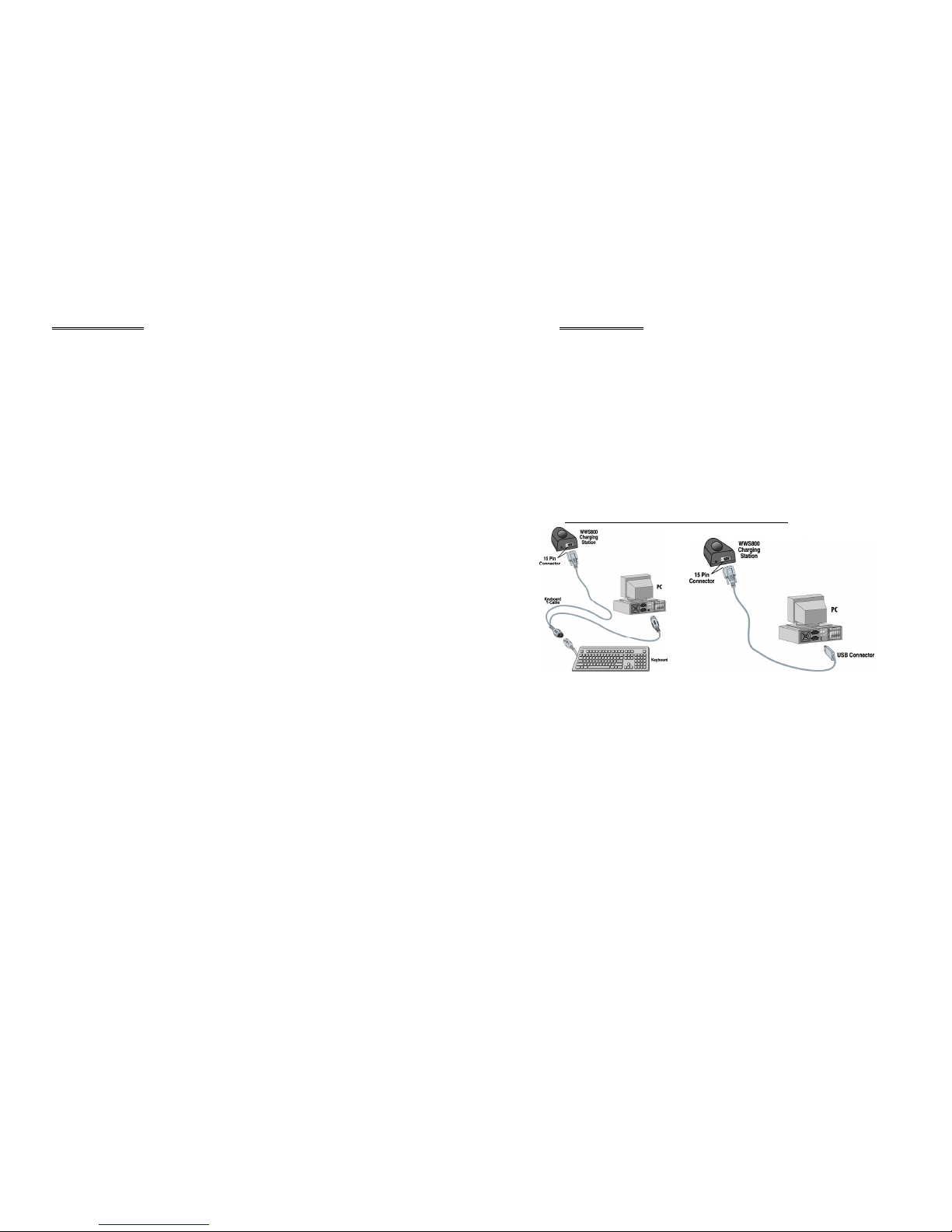
Interface Setting..................................................................5
3.
General Features.................................................................6
3.1
Buzzer.................................................................................6
3.2
Indicator .............................................................................6
3.3
Scan Modes ........................................................................6
3.4
Auto-Sense .........................................................................7
3.5
Re-read Delay.....................................................................7
3.6
Scanner Time-out Duration ................................................7
3.7
Reading Redundancy..........................................................8
3.8
Supported Symbologies......................................................8
3.9
Negative Barcodes..............................................................8
4.
Output Interface (WWS800 Base Unit)..............................9
4.1
Keyboard Wedge Interface.................................................9
4.1.1
Keyboard Type...................................................................9
4.1.2
Keyboard Style - Alphabets................................................9
4.1.3
Keyboard Style – Digits .....................................................9
4.1.4
Capital Lock Status...........................................................10
4.1.5
Alphabets Transmission....................................................10
4.1.6
Digits Transmission..........................................................10
4.1.7
Inter-Character Delay .......................................................10
4.2
USB Interface...................................................................10
4.3
Memory Parameters..........................................................11
4.3.1
Memory Mode..................................................................11
4.3.2
Clear Data.........................................................................11
4.3.3
Send Data .........................................................................11
4.3.4
Memory Data Delay .........................................................11
5.
Bluetooth Serial Port ........................................................12
5.1
Configuring the WWS800................................................12
5.1.1
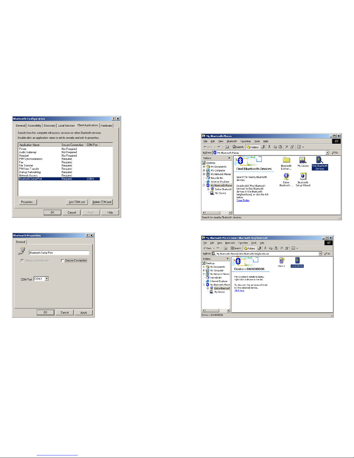
Activate Bluetooth Serial Port Interface...........................12
5.1.2
Authentication & PIN Code..............................................12
5.1.3
Device Name Broadcasting ..............................................12
5.1.4
Update Settings.................................................................13
5.1.5
Timeout ............................................................................13
5.2
Configuring Bluetooth Device Driver ..............................13
6.
Symbology Parameters.....................................................19
6.1
Code39 .............................................................................19
6.2
Italy / French Pharmacode................................................19
6.3
Industrial / Interleave / Matrix 25.....................................19
6.4
Codabar ............................................................................20
6.5
UPCE................................................................................20
6.6
EAN8................................................................................20
6.7
UPCA...............................................................................21
6.8
EAN13..............................................................................21
6.9
MSI...................................................................................21
6.10
Plessey..............................................................................21
6.11
Telepen.............................................................................22
6.12
RSS...................................................................................22
7.
Data Output Format..........................................................23
7.1
Character Substitution ......................................................23
7.2
Prefix / Postfix Code ........................................................23
7.3
Code ID............................................................................23
7.4
Length Code .....................................................................24
8.
Data Editing......................................................................25
8.1
Select Editing Format.......................................................25
8.2
Restore Default Format ....................................................25
8.3
Applicable Conditions......................................................25
8.4
Total Number of Fields ....................................................26
8.5
Dividing Data into Fields .................................................26
8.6
Additional Fields ..............................................................27
8.7
Field Transmission Sequence ...........................................27
8.8
End of Format Programming............................................27
8.9
Activate Data Editing Formats .........................................27
8.10
Exclusive Data Editing.....................................................27
8.11
Programming Examples....................................................27
9.
Configuring your WWS800..............................................29
9.1
Enter Configuration Mode................................................29
9.2
Default..............................................................................29
9.3
List Setting .......................................................................29
9.4
Setting Parameter Values..................................................29
9.4.1
Numeric Parameters .........................................................30
9.4.2
Character String Parameters .............................................30
9.4.3
Key Type/Status Setting ...................................................31
9.5
Exit Configuration Mode..................................................32



 
The WWS800 Cordless Barcode Scanner is the first Wasp Technologies scanner
utilizing Bluetooth Technology. The scanner has a remote range of over 160 feet
and a battery life of over 50,000 scans. The WWS800 uses a CCD long-range
linear imager. This manual contains all the information needed to operate and
configure the WWS800. It is divided into two parts. The first part of this manual
describes the installation, operation and programmable features of the scanner. The
second part of this manual contains the setup barcodes used to configure the
scanner.
The WWS800 is one of the most versatile and flexible cordless barcode scanners
available today. All the features and functions required for up to date barcode
reading are included. Owing to the compact design and extremely low power
consumption, this scanner provides for easy installation and high product durability.
The scanner caters to the requirements of today, while also fulfilling your long-term
needs. The main functions and features provided on the WWS800 are listed below.
• Barcode Readability: Most popular barcode symbologies are supported including
the newest RSS Code.
• Support for negative barcodes.
• Supports eight scan modes.
• Programmable Beeping Tone
• Dual Color Indicator
• Interface Support (base unit): KB Wedge and USB
• Bluetooth Serial Port Profile Support: The scanner can transmit scanned data to
Bluetooth enabled computer/PDA via standard Bluetooth Serial Port
communication.
• Programmable Code ID: Code ID can be individually configured for each
symbology.
• Programmable Length Code
• Programmable Prefix Code
• Programmable Postfix Code
• Character Substitution
• Data Editing: Data can be reorganized according to user programmable formats.
Up to three data editing formats are supported.
• Extremely Low Power Consumption

 
The WWS800 kit contains:
WWS800 Cordless Barcode Scanner
WWS800 Base/Charger dock
Keyboard wedge or USB cable (depending on configuration ordered)
Power Supply for Base/Charger dock
CD containing this manual
Note : For installation and configuration instructions on
Bluetooth Serial Port operation, please refer to the section
“Bluetooth Serial Port”.
   
Keyboard Wedge connection USB connection
Connect the interface cable into the 15-pin connector at the back of the base. The
cable you connect will depend on the interface you ordered. The configurations
shown are the Keyboard Wedge and the USB cable connections.
IMPORTANT: First turn OFF your PC or Laptop that you are connecting the base
cable to. Connect the cable to the base and then plug the other end of the cable into
the appropriate connection on your PC as shown in the figures above.
Connect 5VDC jack of the power supply cable into the DC 5V port located at the
back of the base. Connect the AC plug to an AC outlet and then turn ON your PC.
You are now ready to configure your scanner and base.



   
When you receive your WWS800 Cordless Scanner, it will be in an OFF mode.
This is done to conserve power and for transportation purposes. At the base of the
scanner you will find a small pin hole. Using a straightened paper clip insert the end
of the paper clip into the pin hole and then remove. The scanner will beep and the
LED at the top of the scanner will blink to indicated that the unit is in power ON
mode. The scanner will also power up once inserted into the base.
Please ensure that you power down the scanner if it will not be used for prolonged
periods. This is done by inserting a paper clip into the pin hole at the base of the
scanner. The scanner’s LED will go off and the scanner will power down.
 
Upon powering up, the scanner will try to establish an RF connection with its base.
At this stage, we need to “pair” the scanner and base.
Turn the base upside down and you will find 2 labels.
The first label has the words “SET CONNECTION” and a barcode. The second
label is the serial number.
To link the scanner to the base, scan the “SET CONNECTION” barcode label. The
scanner will beep once. Next, scan the SERIAL number barcode. The scanner will
beep twice, low then high beep. When it establishes RF connection with the base,
the scanner will emit three short ascending beeps indicating that “pairing” had been
established.

  !!"  
To charge your scanner, simply place it in the base. The LED on the top of the
scanner will flash RED while it charges. When the battery is fully charged,
approximately 4 hours if the battery is completely discharged, the LED will remain
solid RED.



# $!
Once you have “paired” the scanner and base, you need to specify the interface type
to your PC. The interface settings are stored in the base. So ensure that you have RF
connection between your scanner and base prior to setting the interface type. For
details on selecting interfaces please refer to the relevant section in this manual.

 %
 &&
The buzzer of the scanner beeps differently to indicate various operating conditions.
• Power On Beep: The scanner will issue a long beep to indicate a successful
power on.
• Good Read Beep: There are four volume levels and four beeping tones
(frequencies) that the user can select from to signify a good read. The available
options are:
Volume: Maximum/Loud/Medium/Minimum
Frequency: 8 / 4 / 2 / 1 kHz
• Error Beep: The scanner will issue a long beep with a low tone to indicate
errors.
• Enter / Exit Configuration Beep: The scanner will issue 6 beeps upon entering /
exiting the configuration mode.
• Setup Beep: In configuration mode, the scanner will normally beep twice when a
setup barcode is read. If the particular setup parameter needs more than one read,
the scanner will only issue a short beep to indicate that there are more setup
barcodes needed to complete the current parameter setting.
 
There is a dual color indicator on top of the scanner. Normally it is off, and will
turn red when there is a good read. The indicator will be green when the scanner is
in configuration mode.
 ' 
There are eight scan modes supported by the scanner. The user can choose the
desired scan mode depending on the application requirements. The supported scan
modes are described below.
• Auto Off Mode: The scanner will start scanning once the switch is
triggered. The scanning continues until either a barcode is read or a preset
scanning period (Scanner Time-Out Duration) is expired.
• Continuous Mode: The scanner continuously scans.
• Auto Power Off Mode: The scanner will start scanning once the switch is
triggered. The scanning continues until a preset scanning period (Scanner
Time-Out Duration) is expired. Unlike the Auto Off mode, the scanner will
continue to scan and the scanning period is restarted each time there is a
successful read.



• Alternate Mode: The scanner will start scanning once the switch is
triggered. The scanner will continue scanning until the switch is triggered
again.
• Momentary Mode: The scanner will scan as long as the switch is
depressed.
• Repeat Mode: The scanner is always scanning just like Continuous Mode.
But now the switch acts like a “re-transmit button”. If the switch is triggered
within 1 second after a good read, the same data will be transmitted again
without actually reading the barcode. This “re-transmit button” can be
triggered as many times as user desired, as long as the time between each
triggering does not exceed 1 second. This scan mode is most useful when the
same barcode is read many times.
• Laser Mode: This is the scan mode most often used on laser scanners. The
scanner will start scanning once the switch is pressed. The scanning
continues until a barcode is read, the switch is released or a preset scanning
period (Scanner Time-Out Duration) is expired.
• Test Mode: The scanner is always scanning. The scanner will decode
repeatedly even with the same barcode.
By default, the scan mode is Auto Off mode for scanners with trigger switch, and is
Continuous mode for switch-less scanners.
  ()
Auto-Sense is used in conjunction with the auto-sense stand. It will enable the
scanner to start scanning once a barcode is brought within Range of the scanner.
This will activate the LED’s and the scanner will start decoding the barcode. The
auto-sense mode works only under Auto Off mode or Laser mode only.
# )*"
If the scanner mode is set to Continuous, Auto Power Off, Alternate, or Momentary
mode, the scanner will prevent accidentally reading the same barcode twice by
using a Re-read Delay (Blocking Time). The barcode must be taken away from the
scanning line longer than the Re-read Delay to allow second reading of the same
barcode. The Re-read Delay can be set by the user.
+ ,- )*
This parameter is used to limit the maximum scanning period when the scan mode
is either Auto Off Mode or Auto Power Off Mode. This time-out duration is
specified in units of second. The default time-out duration is ten seconds.

. !"
This parameter is used to specify the levels of reading (decoding) redundancy. If No
Redundancy is selected, only one successful decoding is necessary for a valid read.
If Three Times Redundancy is selected, it will take 3 successful decodes to make
the reading valid. It is obvious that the more redundancy the user selects, the higher
the reading integrity and thus the slower the reading speed. The user must
compromise between decoding integrity and speed.
 "- /!
Most of the popular barcode symbologies are supported. Each symbology can be
individually enabled or disabled. The scanner will automatically discriminate and
recognize all the symbologies that are enabled. The supported barcode symbologies
are listed below.
• Code 39 (Standard / Full ASCII)
• Italy Pharmacode
• French Pharmacode
• Industrial 25
• Interleave 2 of 5
• Matrix 25
• Codabar (NW-7)
• UPCA (with or without Addon)
• UPCE (with or without Addon)
• EAN8 (with or without Addon)
• EAN13 (with or without Addon)
• Code 93
• Code 128
• EAN 128
• MSI
• RSS14
• Telepen
• Plessey
0 1!2
The scanner can be configured to read negative barcodes. Normally, barcodes are
printed with the color of the bars darker than that of the spaces. But for negative
barcodes, they are printed in the opposite sense just like negative films. The spaces
of the negative barcodes are printed with a color darker than that of the bars.



 3$4  5
The WWS800 is a multi-interface scanner. It can be used as a keyboard wedge
scanner or a USB scanner. The output interface can be programmed using the setup
bar codes found in the Reference Guide.
Please ensure that you have an RF connection between the scanner and the base
prior to selecting the interface type.
 6"/ !$
 
The keyboard wedge interface is enabled by configuring/selecting keyboard type.
The supported keyboard types are listed below.
• PCAT - US, French German, Italian, Swedish, Norwegian, UK, Belgium,
Spanish, and Portuguese KBD
• PS2-30
• IBM 3477 TYPE (Japanese KBD) – requires special cable
• IBM 34XX, 319X & Memorex Telex (122Keys) – requires special cable
 6"/")(/

Keyboard layout style can be selected. There are three options to this setting:
default layout (US or English style), AZERTY layout, and QWERTZ layout. This
setting only works when the keyboard type selected is for US keyboard. The
scanner will make necessary adjustment when sending the ‘A’, ‘Q’, ‘W’, ‘Z’, ‘Y’,
and ‘M’ character according to this setting.
 6"/"7*!

There are two digit layout styles as shown on the following figures. One has its digit
keys on top (upper row), the other has them on bottom (lower row).
The digit layout style can be changed by configuring this setting. There are three
options to this setting: Default, Lower Row, and Upper Row. The scanner will
make necessary adjustments when sending digits according to the setting value of
this parameter. This setting is to be used with the Keyboard Style – Alphabets and
Character Substitution setting, when support to languages not available on the
scanner is needed.
! @ # $
1 2 3 4
Digits on Lower Row

  89

In order to send alphabets with correct case, the scanner needs to know the capital
lock status of the keyboard. Incorrect settings may result in reversed case of
alphabets being transmitted. There are 3 options to this parameter: On, Off, or Auto
Detection. If this parameter is set to Auto Detection, the scanner will automatically
detect the capital lock status of the keyboard before it transmits data.
# (/,- 

User can choose how alphabets are sent by configuring this parameter. The
alphabets can be sent according to their case (the Case Sensitive option), or the case
is ignored (the Ignore Case option) when transmitting.
+ *!,- 

User can choose how the scanner transmits digits by configuring this parameter.
The scanner can transmit digits by using the alphanumeric key or by using the
numeric keypad. The Num Lock status of the keyboard should be ON if numeric
keypad option is selected.
Keyboard
. 
-*"

An inter-character delay of 0 to 255 ms can be configured to match the computer
response time of the keyboard interface. The delay time configured is inserted
between transmitting every character. The longer the delay time configured, the
slower the transmission speed will be. The inter-character delay is zero by default.
 $
A USB interface is available.
1 2 3 4
! @ # $
Digits on Upper Row
Numeric Key Pad
Alpha Numeric Key



 ' - "- 
The scanner can work offline and store data in the internal Flash memory for later
upload to the host. The stored data can be up to 32Kbytes.
 ' - "' 

This setting enables or disables the memory function of the scanner.
 *

The CLEAR label will enable the user to CLEAR or ERASE the data in the
scanner’s memory. The user must also scan the CONFIRM label immediately after
the CLEAR label.
 *

This enables the user to transmit the data in the scanner’s memory to the host. The
interface selected by the user will be used for the transmission. During the
transmission, the red LED of the scanner will be flashing.
  ' - "** "

This will enable the user to set a delay between each data records in memory at time
of transmission.

# 
The WWS800 can be configured to use a standard Bluetooth Serial Port as the data
output interface. This allows the WWS800 to send the scanned bar code data to a
Bluetooth enabled computer or mobile device directly without the need of the
WS800 base unit (however, a charging dock is still needed for recharging the
scanner’s battery).
In this section, a step-by-step procedure for installing and configuring the WWS800
for a Bluetooth Serial Port configuration is illustrated. Bluetooth
transceivers/dongles come with their own hardware driver. Bluetooth device
drivers for Windows and WinCE/Pocket PC are available from the Bluetooth
transceiver/dongle manufacturer. In the following example, a WIDCOMM driver is
used.
# $!!  
Before starting the configuration, the scanner must be powered up. If you have not
done so, please follow the procedures described in section 2.2 “Power Up the
WWS800 Cordless Scanner” to power up the scanner.
The first step of the configuration is to put the scanner in configuration mode. To
do this, scan the “Enter Setup” bar code in the Reference Guide. After the device is
configured, scan the “Update” bar code to save the new settings and put the scanner
back to normal operation mode.
# (2$

Scan the “Activate Bluetooth Serial Port” bar code in the Reference Guide to
change the interface type to Bluetooth Serial Port.
# (:1

Connection authentication is available if communication security is desired. Once
this setting is enabled, a user configurable PIN code is verified during connection
establishment. The scanner will refuse connection if the PIN code is incorrect. Up
to six characters can be specified for a PIN code.
# *21- !

The scanner can be configured to hide itself by NOT broadcasting itself on the air.
This can prevent an unwanted connection to a Bluetooth enabled computer or
mobile device. For the initial connection setup, this setting must be enabled.



#  !
After all the desired settings are completed, the “Update” bar code must be scanned
to make the new settings effective. The scanner will re-start itself after the “Update”
bar code is scanned.
## ,- 

The scanner will stay active only for one minute waiting for connection. If there is
no connection request during that period, the scanner will go to power down mode
to conserve power with three descending tones as indication. To return the scanner
to active mode, pull the trigger. Once there is a successful connection, the
scanner will stay active until the connection is closed (for example, when the
host application closes the COM port). After the connection is closed, the
scanner will wait for new connection request for one minute before it goes to power
down mode.
# $!!*2*2
Please follow the procedures below to configure the Bluetooth driver on the host
system.
Go to “My Computer”
Double click on the “My Bluetooth Places”.

Right click “My Device”. Select “Property”
Select “Client Applications” tab.



Select “Bluetooth Serial Port” from the list.
Click “Property” button.
“Secure Connection”. If you have enabled the Authentication and have configured
a PIN Code on the WWS800, leave “Secure Connection” checked. Otherwise,

uncheck it.
Click “Apply” and “OK”
Click “OK” to go back to “My Bluetooth Places”
“Wake up” the WWS800 by pulling the trigger.
Double click “Find Bluetooth Devices”.
Now the WWS800 should be shown on the screen with the scanner’s serial number
as the device name. For this example, the device name is “SW3000006”.