Xtool PS70PRO User manual

PS70PRO
Diagnosis System
User Manual

PS70PRO Diagnosis System
1
Declaration
1. The manual is designed for the usage of PS70PRO, applying to PS70PRO
automotive diagnosis platform. No part of this manual is allowed to be reproduced,
stored in a retrieval system or transmitted, in any form or by any means (electronic,
mechanical, photocopying, recording, or otherwise), without the prior written
permission of Xtool.
2. This electronic control system diagnostic unit is for professional vehicle
maintenance technicians. It has some reliability, but it can not rule out vehicle
damage and loss, caused by customer technical problems, vehicle problems or other
factors, for these reasons, users need to take risks.
3. Use the device only as described in this manual. The user will be responsible
solely for the after-effects of violating the laws and regulations caused by using the
product or its data information, Xtool will not bear any legal responsibility for that.
4. Xtool shall not be liable for any incidental or consequential damages or for any
economic consequential damages arising from the accidents of individual users and
the third parties, misuse or abuse of the device, unauthorized change or repair of
the device, or the failure made by the user not to use the product according to the
manual.
5. All information, specifications and illustrations in this manual are based on the
latest configurations and functions available at the time of printing. Xtool reserves
the right to make changes at any time without notice.
6. is theregistered trademark of Shenzhen Xtooltech Co., Ltd.
7. In the countries that the trademarks, service marks, domain names, logos and the
name of the company do not be registered, Xtool claims that it still reserves the
ownership of the unregistered trademarks, service marks, domain names, logos and
the company name. All other marks for the other products and the company’s name
mentioned in the manual still belong to the original registered company. Without
written permission from the trademark holder, no one shall use the trademarks,
service marks, domain names, logos and company name of Xtool or other
companies mentioned.
8. Please visit http://www.xtooltech.com for more information about PS70PRO.
9. Xtool reserves the right for the final interpretation of this manual content
PS70PRO Diagnosis System.

PS70PRO Diagnosis System
2
Contents
CHAPTERⅠAbout PS70PRO......................................................................................3
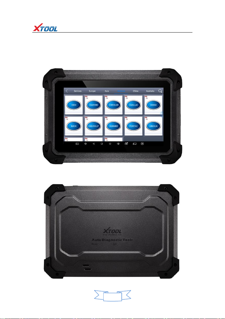
1. Appearance ............................................................................................................3
1.1. Front View ...........................................................................................................3
1.2. Back View ............................................................................................................3
2. Layout of PS70PRO Tablet ......................................................................................4
3. PS70PRO Technical Parameters..............................................................................4
CHAPTERⅡHow to use PS70PRO..............................................................................5
1.PS70PRO Activation.................................................................................................5
1.1. Please activate PS70PRO before you use it to test vehicles.................................5
1.2. Connect to WiFi first............................................................................................5
2. PS70PRO Main Interface and Functional Buttons Descriptions...............................6
2.1. Main Interface .....................................................................................................6
2.2. Sub-menus and Function Buttons........................................................................6
2.3. Toolbar Function Buttons ....................................................................................7
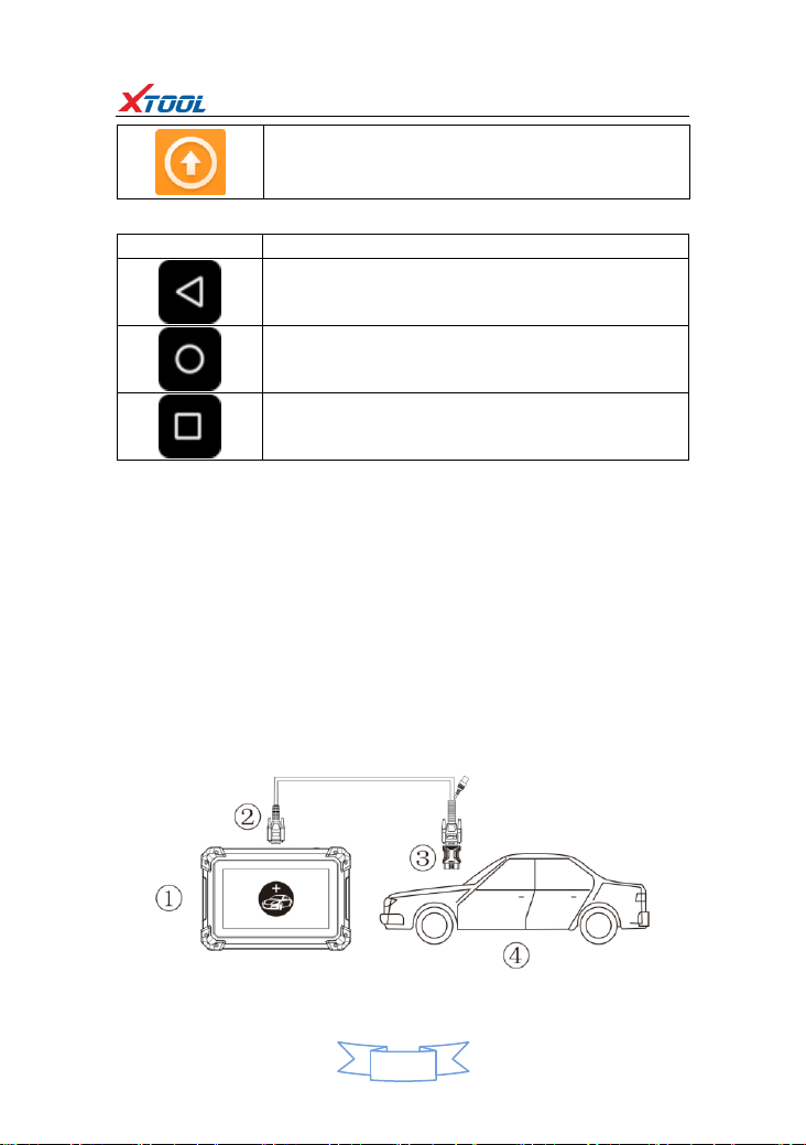
3. Vehicle Connection Diagnosis.................................................................................7
3.1. Vehicle Connection Test ......................................................................................7
3.2. Precautions before Use........................................................................................8
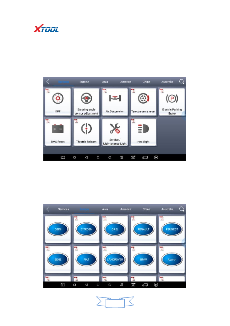
4. Diagnosis ................................................................................................................9
4.1. Menu Options......................................................................................................9
4.2. Test Functions....................................................................................................10
4.3. Read ECU ...........................................................................................................12
4.4. Read DTCs..........................................................................................................13
4.5. Clear DTCs..........................................................................................................13
4.6. Read Live Data...................................................................................................14
4.7. Special Functions ...............................................................................................17
4.8. Actuation/Active/Components Test ..................................................................17
5. Settings.................................................................................................................19
6. Diagnostic Reports................................................................................................20
6.1. PDF Files ............................................................................................................20
6.2. Pictures..............................................................................................................21
6.3. Data Playback ....................................................................................................21
7. UPDATE.................................................................................................................21
8. Xtool Cloud System(Coming soon)........................................................................22
9. Remote Access......................................................................................................22
CHAPTERⅢDiagnostic Link Connectors of Different Vehicle Models ....................23
1. Diagnostic Link Connectors Diagram of Some Vehicle Models .............................23
2. Location Diagram of Vehicle Diagnostic Link Connectors .....................................26
3. Diagnostic Link Connectors Terminal Definition and Communication Protocols...27
3.1. Standard OBDII Diagnostic Link Connector ........................................................27

PS70PRO Diagnosis System
3
CHAPTERⅠAbout PS70PRO
1. Appearance
1.1. Front View
1.2. Back View

PS70PRO Diagnosis System
4
2. Layout of PS70PRO Tablet
① ② ③
①MicroUSB:Battery charge or data synchronization with PC
②DB15 Port:Supports wired connection with car by the cable
③Power Button: Power on or power off
3. PS70PRO Technical Parameters
Operation System:
Processor:
Memory:
Display:
Sensors:
Audio Input/Output:
Power and Battery:
Power Voltage:
Power Consumption:
Operating Temperature:
Humidity:
Dimension (L×W×H):
Android
Quad-core 1.6GHz Processor
1G RAM, 16G FLASH
7.0 inch touch screen with 1024×600 resolution
Gravity Sensor,Ambient Light Sensor
Microphone, Dual Speakers, 4-Band 3.5 mm
stereo/standard headset jack
4000mAh, 3.7V lithium-polymer battery
5V
8W
-20 to 50℃(-4 to 126℉)
<90%
218×150×29mm

PS70PRO Diagnosis System
5
CHAPTERⅡHow to use PS70PRO
1. PS70PRO Activation
1.1. Please activate PS70PRO before you use it to test vehicles.
1.2. Connect to WiFi first.Please fill in the company name and mailbox, then click
OK to complete the activation.

PS70PRO Diagnosis System
6
2. PS70PRO Main Interface and Functional Buttons Descriptions
2.1. Main Interface
Tap on PS70PRO application, the main interface and sub-menus show up as below.▼
2.2. Sub-menus and Function Buttons
Function Buttons
Descriptions
Configures PS70PRO Tablet to perform as diagnosis system.
It can read diagnostic information, view live data, perform
actuation tests and special functions and etc.
Users can view all the diagnostic reports and diagnostic
data generated in the process of diagnosis.
Select“Settings”, users can make the language setting and
other system related settings.
Online Communication platform.(Coming soon)
Provide remote assistance.

PS70PRO Diagnosis System
7
Click UPDATE after it connects with internet, then you can
download the latest diagnostic software directly.
2.3. Toolbar Function Buttons
Function Buttons
Descriptions
Returns to previous interface
Returns to the main interface of Android System
Shows recently used applications
3. Vehicle Connection Diagnosis
3.1. Vehicle Connection Test
3.1.1. Wire Connection ①→②→③→④
a. Turn on PS70PRO tablet
b. Connect cables and PS70PRO in following order: ①→②→③→④
c. Switch on the ignition and tap on PS70PRO application to test vehicles. (Shown as
follows)
①PS70PRO Mainframe ② Main Test Cable ③ OBDⅡ-16 ④ Vehicle

PS70PRO Diagnosis System
8
3.2. Precautions before Use
3.2.1. The vehicle power supply has to meet the normal voltage limits DC4.8V---5V.
3.2.2. When pull and plug test wire harness, users should pinch the front-end of the
wire harness to pull and plug, not pull the middle section of the wire harness. Users
should check the corresponding direction of the port and plug in horizontally when
they plug the wire harness, instead of inserting in an oblique way, which may
damage the terminal.
3.2.3. When taking some special functions tests, users are required to operate the
device according to operating instructions. For vehicle, it has to strictly meet the
requirements, for example, the conditions that some vehicle models need to be
reached are as follows: engine temperature 80℃/105℃, turn off the loads (such as
headlights, air-conditioner, etc.), put accelerator pedal in released position, etc.
3.2.4. The ECU for domestic vehicle models in China are relatively disorderly, so
when users meet conditions, such as the car can not be tested or the test data is
wrong, they should consider whether the selected menu corresponds to the tested
electronic control system, or they can find the car ECU and select the right menu
according to the model number on the ECU label.
3.2.5. If users can not find the tested vehicle model or electronic control system on
PS70PRO test menu, they may need to update the software or consult Xtool
technical service department.
3.2.6. Do not to have connection test by using harness not from Xtool to avoid
unnecessary losses.
3.2.7. Do not take power off directly in the communication between PS70PRO and vehicle.
Users should cancel the task and return to the main interface, then power off.
3.2.8. The device should be put and lifted slightly to avoid collision when using
PS70PRO. When click the screen, touch it gently to guarantee the service life of the
touch screen.
3.2.9. During long period of non-use, please disconnect the power and turn it off.

PS70PRO Diagnosis System
9
4.Diagnosis
4.1. Menu Options
4.1.1. After PS70PRO tablet connected to vehicle via main cable, diagnosis can be
performed now. The diagnostic interface comes up as below.
4.1.2. Users can choose menu based on their actual needs: selection for Europe
means entering European cars menu, selection for Asia means entering Asian cars
menu, selection for America means entering American cars menu, selection for
China means enteringChinese cars menu. Users also caninput vehicle model to search.

PS70PRO Diagnosis System
10
4.2. Test Functions
4.2.1. Take Volkswagen car for example, select Diagnosis, then select Europe Car,
users can see Volkswagen’s VW word. If the VW word has not been seen, please
swipe up and down or enter the car model to research.
Different vehicles have slight different menus.
Common main function menu includes the following options:
Read ECU: this function is to read ECU version information, which is the equivalent
of “System Identification”or “System Information”in some electronic control
systems, all mean to read ECU related software and hardware versions, models and
production date of diesel engine, part number, etc. It is convenient for us to make
record in the maintenance process, and it also makes later data feedback and
management easier.
Read DTCs: read trouble codes stored in ECU.
Clear DTCs: clear current and historical trouble codes memory in ECU, under the
premise that all the troubles are eliminated. The trouble codes can not be erased
without eliminating all the troubles, which will cause the diagnostic tool always

PS70PRO Diagnosis System
11
reading the trouble code because the code will always be saved in ECU. Suggestion:
users should better not to clear trouble codes, we need record the trouble details
after reading code, which is provided as reference for maintenance. After dealing
with troubles, there will be no trouble code when we re-read.
Read Live Data: that is to read the parameters of running engine, such as oil
pressure, temperature, engine speed, fuel oil temperature, coolant temperature,
intake air temperature, etc. Based on these parameters, we can judge directly
where the problem lies, which helps to narrow the scope in maintenance. For some
vehicles, during their actual operation, the problems such as performance
characteristics offset, sensitivity reduction, can be judged in live data. This function
needs us very familiar with engine parameters, for instance, when idle speed is
800RPM or 750RPM, coolant operating temperature is between 80 and 105℃, what
are the operating voltage and time of each sensor and actuator?
Special Functions: depends on vehicle models.
Actuation/Active/ Components Test: mainly to judge whether these actuating
components of engine are working properly.
4.2.2. Toolbar function buttons descriptions
Function Buttons
Descriptions
Returns to previous interface
Print testing data
Click it to record the data, click again to send your
feedbacks to XTOOL after service center

PS70PRO Diagnosis System
12
Record data feedback button as shown below, showing diagnostic software version
and various information in the diagnostic process.
4.3. Read ECU
This function is to read ECU version information, which is the equivalent of “System
Identification” or “System Information” in some electronic control systems, all mean
to read ECU related software and hardware versions, shown as below.

PS70PRO Diagnosis System
13
4.4. Read DTCs
Select Read Fault Codes to read trouble codes stored in ECU. Screen will show the
trouble code and its definition when read the trouble codes, shown as below.
Tip: In the process of diagnosis, if the device shows “System is OK” or “No Trouble
Code”, it means there is no related trouble code stored in ECU or some troubles are
not under the control of ECU, most of these troubles are mechanical system troubles
or executive circuit troubles, it is also possible that signal of the sensor may bias
within limits, which can be judged in Live Data.
4.5. Clear DTCs
4.5.1. Return to the previous step, select Clear DTCs to clear current and historical
trouble codes memory in ECU. Performing this function will clear all the current and
historical trouble codes. Make sure whether the trouble codes have been recorded
before clearing, shown as below.

PS70PRO Diagnosis System
14
4.5.2. Click YES to make clear confirmation, if the communication is normal, it will
show “Trouble Codes Successfully Cleared” or “Trouble Codes Cleared”. Generally,
users need re-read trouble codes after cleaning them to confirm whether the
trouble codes have been cleared.
4.6. Read Live Data
Auto ECUs send out operating parameters and working status of various components
in the form of Electronic Signal, here Electronic Signal refers to Live Data. Common
Engine Live Data includes Engine Speed, Throttle Position Sensor Voltage, Oxygen
Sensor Voltage, Coolant Temperature, Spark Advance Angle, Idle Speed Switch State,
Intake Air Temperature, Intake Pressure, etc.

PS70PRO Diagnosis System
15
Tips: Live Data is the important function for maintenance technicians further diagnose
the troubles. This function needs maintenance technicians to be very familiar with
sensor data of each system, control signals and control modes, all which are the
indispensable basis of using Live Data function for maintenance technicians. (The
following is test conditions and typical values of common live data)
Test Items
Unit
Normal Data
Test Conditions & Typical
Values
1.Engine Speed
rpm
0-6000
Engine warmed-up:
750-850rpm
2.Engine Coolant
Temperature
℃
-40-150
Engine warmed-up: 85-95℃
3.Throttle
Percentage
0-100
Throttle closed:0%, Throttle
wide-open: >85
4.Injecting Pulse
Width
ms
0-15
Engine warmed-up: 3.5-4.5ms
5.Intake Air
Temperature
℃
-40-150
Show value a little higher
than ambient temperature
6.Battery Voltage
v
0-15
Idle speed: 1.5-13.5V
7.Injection
Closed-Loop
correction
0-1.99
8.Load
ms
0-15
9. Angle of Ignition
Advance
℃
0-50
Engine warmed-up: 5-15 ℃
variations
10.Air Intake
kg/h
0-255
Engine not started: 0
11.Intake Pressure
hpa
0-1013
Engine not started: 1013hpa
12. Idle-speed
Adjustment Status
0-255
13.Oxygen Sensor
mv
0-1000
Engine warmed-up: 50-960mv
variations

PS70PRO Diagnosis System
16
Display Modes
There are two modes to view Live Data, users can choose optimum mode according
their own needs and different parameter types.
Dashboard Mode: Display parameters in the form of simulating instrument graphics.
Graph Mode: Display parameters in the form of graph.

PS70PRO Diagnosis System
17
4.7. Special Functions
More special functions will be found in different vehicle models.
4.8. Actuation/Active/Components Test
Test Conditions: Ignition on engine off.
If engine started or rotation speed signal recognized, actuating component
diagnosing will be interrupted.
In the process of actuating components diagnosis, single component will always be
in the trigger status until the next component being activated.
Before repeating actuating components diagnosis, users should start engine in
short-time, or turn ignition off for 2 seconds.
Actuating components can be checked by hearing or touching.
In the process of all actuating components diagnosis, electric fuel pump is always
working.
10 minutes later, actuating components diagnosing is terminated.
Actuating Component: It is responsible for executing various instructions issued by
ECU, which is the instruction completer.

PS70PRO Diagnosis System
18
4.8.1. Return to Dynamic Diagnostic Data, enter Actuating Components Test and it will show
the menu of the actuating components that carry out action test, shown as below.
Tip: Actuating Components Test performs function tests for parts of system
actuating components. When performing this function, the diagnostic tool will take
action test by simulating ECU signal to judge whether the actuating components or
circuits are good.
Return to Dynamic Diagnostic Data, enter Actuating Components Test and it will
show the menu of the actuating components that carry out action test.

PS70PRO Diagnosis System
19
5. Settings
Click Settings: users can set the language, unit and other system related options.
Languages: select the language. Please tick the needed option from multi-language options
ontheright.
Units: Select unit of measurement. Users can tick Metric or English measurement.
System Settings: Android system setup, such as wireless, audio frequency, light
sensation, etc.
Other manuals for PS70PRO
2
Table of contents
Other Xtool Diagnostic Equipment manuals

Xtool
Xtool Anyscan A30D User manual

Xtool
Xtool PS2 User manual

Xtool
Xtool TP Series User manual

Xtool
Xtool D8 User manual

Xtool
Xtool Anyscan A30 User manual

Xtool
Xtool X100PAD Elite User manual

Xtool
Xtool N9EV User manual

Xtool
Xtool PS70 Pro User manual

Xtool
Xtool PS90 User manual

Xtool
Xtool A30 Pro User manual