Haldex DIAG++ Manual

Innovative Vehicle Solutions
OPERATOR’S GUIDE

2Innovative Vehicle Solutions 2022
DIAG++ Operator‘s Guide
Notes on the use of this manual
This manual has been designed to assist personnel in satisfactory installation and operation of Haldex DIAG++.
It is expected that this manual will be in possession of the appropriate person throughout their ‘training’ and
‘experience’ and that the manual will be used as a teaching aid following supervision of a Haldex engineer or a
reminder of the correct procedure for operating Haldex DIAG++ software.
› Use appropriate spare-parts documentation when obtaining spare parts
› Use only genuine Haldex parts in repairs
› Due to continuous development the right is reserved to alter the specification without notice
› No legal rights can be derived from the contents of the manual
› Duplication, translation and reprinting are prohibited without permission from Haldex Brake Products

3
2022 Innovative Vehicle Solutions
DIAG++Operator‘s Guide
Contents
Installation
Introduction ..............................................................................6
Installation................................................................................7
Starting DIAG++ ..................................................................... 12
Settings .................................................................................. 13
EBS Operation
ECU connections..................................................................... 16
Home screen........................................................................... 24
Basic diagnostics (service menu).............................................. 27
Setting parameters (ECU configuration) .................................. 33
Auxiliary operation.................................................................. 43
EB+ Soft Docking.................................................................... 79
End of line test (EOLT) .............................................................86

4Innovative Vehicle Solutions 2016
4 52022
Innovative Vehicle Solutions Innovative Vehicle Solutions
2022
Operator‘s GuideDIAG++

5
2016 Innovative Vehicle Solutions
INSTALLATION
Introduction 6
Installation 7
Starting DIAG++ 12
Settings 13
4 52022
Innovative Vehicle Solutions Innovative Vehicle Solutions
2022
Operator‘s Guide DIAG++

6Innovative Vehicle Solutions 2022
DIAG++ Operator‘s Guide
Introduction
With DIAG++ you can use a standard personal computer to read and delete diagnostic codes, program vehicle
parameters and end of line test (EOLT) for Haldex EB+ 4.0 EBS (referred as EBS in the rest of the document). The
USB PC Interface (dongle) allows communications between a standard PC and the EBS ECU. Connections to the
USB PC Interface (dongle) are made through a cable connecting to a USB port on the computer and another
cable connecting the diagnostic interface to the ECU. The vehicle parameter data is stored inside the ECU. It will
remain intact even after electrical power is removed from the EBS.
Note: The USB PC Interface (dongle) is different to the RS232 interface pods as used on earlier systems.

7
2022 Innovative Vehicle Solutions
DIAG++Operator‘s Guide
Installation
Minimum system specication
The minimum PC or laptop specification to run the DIAG++ package is as follows:
Processor - No particular requirement
RAM - 256 megabytes
Hard drive - 30 megabytes free
MS Window 10
In addition to the above, a USB port is required to connect to the USB PC Interface (dongle).
Downloading DIAG++
The latest DIAG++ version software can be downloaded from the Findex section of the Haldex web site.
To download follow:
› Go to http://www.haldex.com
› Click on Trailer Guide Application
› Click on service
› Download software
Follow installation procedure

8Innovative Vehicle Solutions 2022
DIAG++ Operator‘s Guide
Installing the software
The software must be installed before the connection of the USB dongle.
› Switch “on” your machine and enter into the desktop mode of your PC, then unzip the DIAG++ .zip file
› Create a desk top short cut to Haldex.Diagnostics.exe in publish directory of unzipped DIAG++
In addition to the application folders, the following folder structure is added to your computer when DIAG++ first
runs.
On Windows 10 the Haldex folder will be located in
C:\Users\Public\Public Documents. Haldex
DIAG++
DTC reports
ECU AUX only setup files
ECU Modification records
ECU Programming records
ECU setup files
EOL reports
EOL reports (automated)
FPF
Setup

9
2022 Innovative Vehicle Solutions
DIAG++Operator‘s Guide
The PC Interface (dongle) is provided with a multi function LED to confirm correct function of the unit as follows:
› Orange: Indicates connection to USB port
› Red: Indicates connection to USB and EBS
› Green: Indicates data is being transmitted
Installing the hardware
The DIAG++ interface kit is comprised of the USB PC Interface (Dongle), together with its connecting cables and a
transit case.
950 800 909 Interface kit
Part number Description
815 023 001 USB PC Interface (DIAG++)
042 707 309 USB cable
950 800 912 Diagnostic cable kit
Part number Description
814 036 001 ECU / PC Interface cable (6.5 m)
844 511 465 EB+ 4.0 CAN to PC interface cable (6.5m)
815 018 001 EB+ ISO diagnostic cable
814 011 001 EB+ SOV / PC Interface cable (6.5 m)
042 623 719 Transit case

10 Innovative Vehicle Solutions 2022
DIAG++ Operator‘s Guide
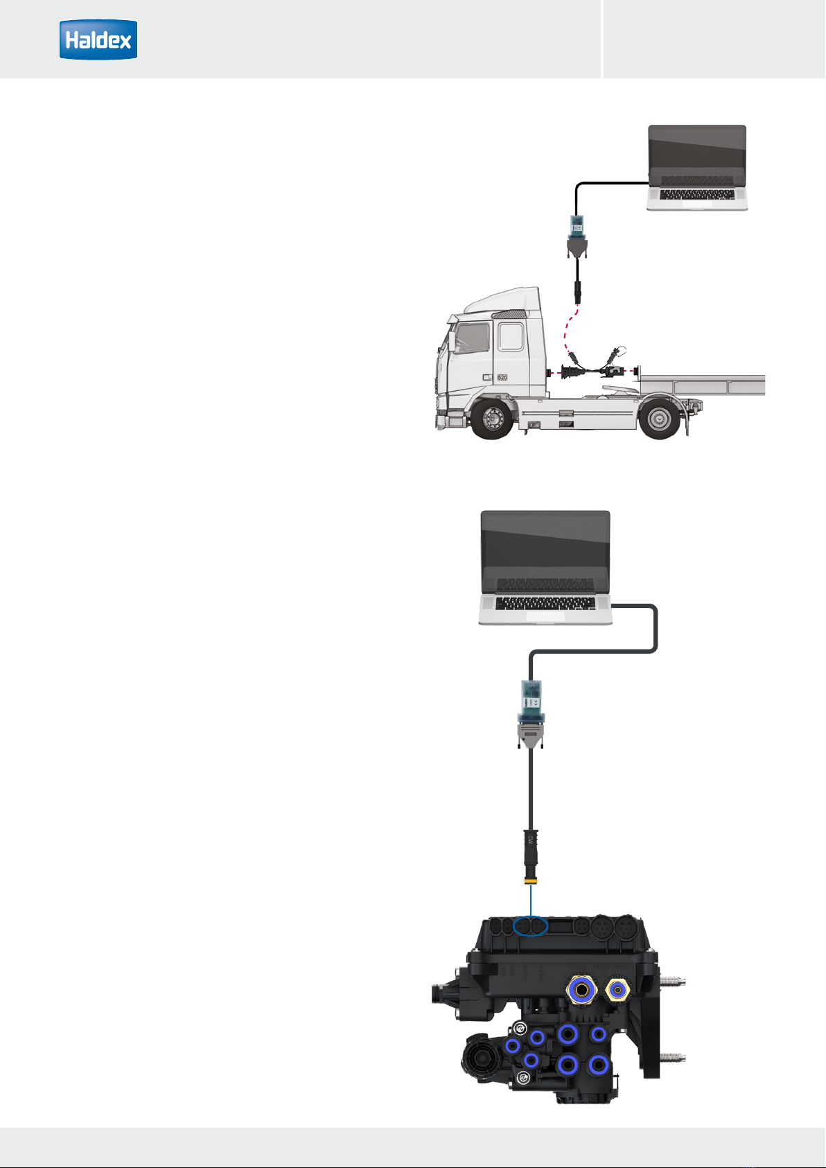
Connecting a PC directly to EB+ 4.0
To access the ECU directly, connect one end of the USB
cable (042707309) into a USB port on the back of your
PC or laptop and the other end into the PC Interface
(815023001).Then connect the PC Interface to either
T-CAN or H-CAN connector on the EB+ 4.0 using cable
series 844 511 xxx.
The LED light on the PC Interface should now be ‘on’,
coloured orange
Power the EB+ 4.0 EBS from an external 24 V dc supply
(i.e. correctly rectified and smoothed) or a tractor unit.
The LED light on the PC Interface should now be ‘on’,
coloured red.
If it is not, please check your connections and try again.
PC Interface 815 023 001
844 511 XXX
USB cable 042 7073 09
Connect to T-CAN or H-CAN
Connecting to EB+ 4.0 via ISO 7638
The ECU can be accessed by using the EB+ ISO diag-
nostic cable (815018001).
Disconnect the ISO 7638 truck to trailer cable and
connect the EB+ ISO diagnostic cable (815018001)
between the truck and trailer.
Connect the PC Interface to the ISO diagnostic cable
using the PC interface cable (814011001).
Connect the PC Interface to the PC USB port using the
USB cable (042707309).
USB cable 042 7073 09
PC Interface 814 011 001
ISO diagnostic 815 018 001

11
2022 Innovative Vehicle Solutions
DIAG++Operator‘s Guide
Updating the USB dongle driver
The USB dongle driver software can be updated to the latest revision.
The required files have been downloaded along with the DIAG++ software and can be found here:
C:\Program Files\Common Files\Haldex\USB
› Run the downloaded dongle driver setup file
CDM21228_Setup.exe
› Follow the on screen instructions to install the
program
› Accept the agreement, click on “next” to proceed
› Software updating
› Software update now complete
› Click on “finish” to proceed
› Restart your computer to apply these changes
Updating the USB dongle software
The USB dongle software can be updated to the latest revision.
The required files have been downloaded along with the DIAG++ software and can be found here:
C:\Program Files\Common Files\Haldex\USB
› Run the downloaded dongle setup file
CDM21228_Setup.exe
› Follow the on screen instructions to install the program
› Switch “off” the power to the ECU
› Switch “on” the power to the ECU
› Software updating
› Software update now complete

12 Innovative Vehicle Solutions 2022
DIAG++ Operator‘s Guide
Starting DIAG++
Connect the USB dongle to the PC
Click on the DIAG++ short cut to start the programme.
If the security warning is displayed click on the run icon
to start DIAG++
The dongle is provided with a multi function LED to confirm correct function of the unit as follows:
Orange: Indicates connection to USB port
Red: Indicates connection to USB and EB+ 4.0 EBS
Green: Indicates data is being transmitted
Power up the ECU. During the self check procedure the
system displays the following functions:
the trailer EBS warning light comes ‘on’ and stays ‘on’.
One audible cycle is produced by the EPRV’s
(EBS valves).
At the same time the LED on the USB dongle
will illuminate ‘red / green’ to show that it is
communicating with the ECU.
The EBS layout schematic should now be showing in
the browser window.
If no EBS layout is shown, click on the binoculars to
auto search for the correct PC connection port.
Red / green led

13
2022 Innovative Vehicle Solutions
DIAG++Operator‘s Guide
Settings
The DIAG++ options can be selected by clicking on the settings link.
DIAG++ only supports EB+ 4.0 EBS
The DIAG++ software can be configured by the user, using the available icons.
› Language - not active at the moment
› General options - not active at the moment
› EOLT settings
› File paths

14 Innovative Vehicle Solutions 2016
14 152022
Innovative Vehicle Solutions Innovative Vehicle Solutions
2022
Operator‘s GuideDIAG++

15
2016 Innovative Vehicle Solutions
EBS
ECU connections 16
Home screen 24
Basic diagnostics (Service menu) 27
Setting parameters 33
Auxiliary operation 43
Soft Docking 79
End of line test (EOLT) 86
14 152022
Innovative Vehicle Solutions Innovative Vehicle Solutions
2022
Operator‘s Guide DIAG++

16 Innovative Vehicle Solutions
DIAG++
2022
Operator‘s Guide
Example - Premium 2M EBS chassis components
Item Description Notes
1 EB+ 4.0 assembly Premium version shown
2 EB+ label
3 ISO 7638 7-pin socket assembly
4 ISO 12098 / PWR-B Optional safety back up cable & Super AUX / Additional inputs
5 EB+ Info Centre
6 Sensor assembly
7 Exciter
8 RTR Programmable via DIAG++
9 Lift axle Programmable via DIAG++
10 Lining Wear System (LWS) Programmable via DIAG++
7
S1B
S1A
S2B
S2A
6
6
6
1
2
3
4
5
10
8 9
6
7 7
7
S1B
S1A S2B
S2A AUX 0
T-CAN
H-CAN
S-CAN
PWR-B
PWR-A
AUX 1
AUX 2
AUX 3
AUX 4
AUX 5
ECU connections

17
2022 Innovative Vehicle Solutions
DIAG++Operator‘s Guide DIAG++
3
12 13111098
2 1
45
67
14
No. Description
1 ISO 7638 PWR-A
2 ISO 12098 / PWR-B
3 S-CAN
4 H-CAN
5 T-CAN
6 Sensor S2A
7 Sensor S1A
No. Description
8 AUX 5
9 AUX 4
10 AUX 3
11 AUX 2
12 AUX 1
13 AUX 0
14 Sensor S2B
15 Sensor S1B
15
Premium 2M EBS connections

18 Innovative Vehicle Solutions
DIAG++
2022
Operator‘s Guide
AUX 1 - 3
COLAS+
Retarder
Trailer lamp
ILAS-E+ front
ILAS-E+ rear
AUX power
Steer axle lock
Service lamp
Overload lamp
Remote overload lamp
Stability lamp
ILAS-E+ front manual
ILAS-E+ rear manual
General purpose output
TA+
Speed lock
TPMS lamp
AUX 4 / AUX 5
Lining wear sensor
General purpose input
Control line sensor
Mechanical height
sensor
Mechanical height
sensor remote
External pressure sensor
Premium EBS auxiliary operation
AUX 0
COLAS+
Retarder
Trailer lamp
ILAS-E+ front
ILAS-E+ rear
AUX power
Steer axle lock
Service lamp
Overload lamp
Remote overload lamp
Stability lamp
ILAS-E+ front manual
ILAS-E+ rear manual
General purpose output
TA+
Speed lock
TPMS lamp

19
2022 Innovative Vehicle Solutions
DIAG++Operator‘s Guide DIAG++
H-CAN
TPMS
Soft Docking
EB+ Info Centre
PC interface
S-CAN
1M Slave
Premium EBS CAN operation
T-CAN
Telematics (Customer)
PC interface

20 Innovative Vehicle Solutions
DIAG++
2022
Operator‘s Guide
2 sensors, 2 modulators, 4 AUX, with EB+ Soft Docking
Example - Wiring Schematic
10
4
6 6 117
9
8 8 3
2
1
Junction box
Additional ECU
Customer specific
installation
Telematics
Customer specific
installation
ISO12098
C1
C7
C8
C9
C13
5
1
C3 C4 C5
C6
C2
C2
C11
C10
C12
Key:
Cables
Options
C1
ISO7638
DIAG+ Interface
PWR-A
Sensor S1B
Sensor S1A
COLAS+ ILASE®-E+ ILASE®-E+ Lining Wear Sensing Traction help switch
S1B
S1A
S2B
S2A
AUX 0
T-CAN
H-CAN
S-CAN
PWR-B
PWR-A
AUX 1
AUX 2
AUX 3
AUX 4
AUX 5
T-CAN T-CAN
EB+ Soft Docking TPMS
Table of contents
Other Haldex Diagnostic Equipment manuals