DENTAURUM orthoX scan User manual

EN
Instructions for use
3D model scanner orthoX®scan.

Contents
1 General information ..................................................................................................................................................... 3
2 Product description ....................................................................................................................................................... 3
3 Technical data ................................................................................................................................................................ 3
4 Safety instructions ........................................................................................................................................................ 4
5 Scanner description....................................................................................................................................................... 5
5.1 Scanner components............................................................................................................................................... 5
5.1.1 Rear view..................................................................................................................................................... 5
5.1.2 Front view.................................................................................................................................................... 5
5.1.3 Interior view................................................................................................................................................. 6
5.2 Operation of orthoX®scan....................................................................................................................................... 6
5.3 Model holder .......................................................................................................................................................... 6
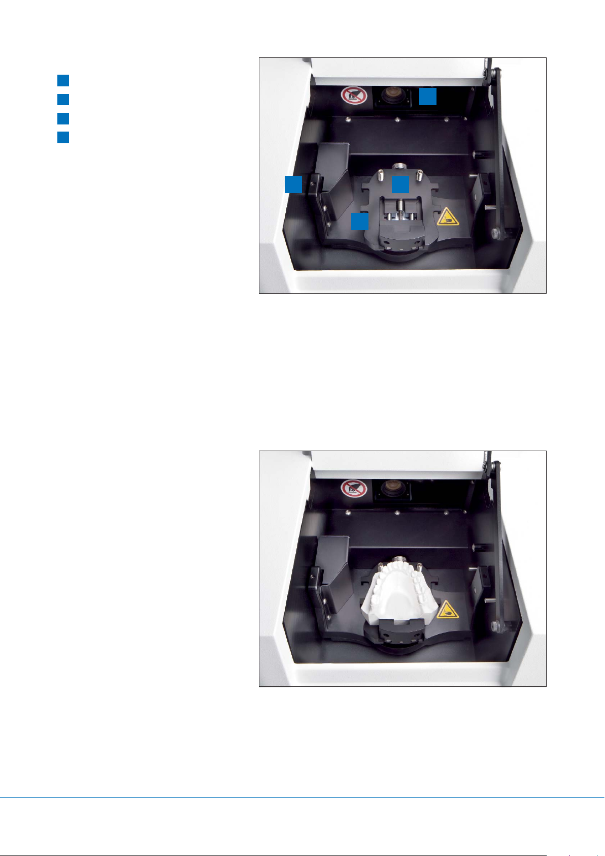
6 Placing model in the 3D model scanner orthoX®scan ................................................................................................ 7
6.1 Securing model on model holder............................................................................................................................. 7
6.2 Placing the upper and the lower model in occlusion in the model holder................................................................. 7
6.3 Placing model holder in the orthoX®scan model scanner ......................................................................................... 7
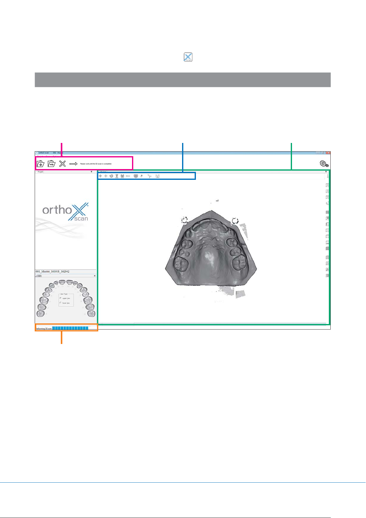
7 Operating orthoX®scan scanner software .................................................................................................................. 8
7.1 Program interface.................................................................................................................................................... 8
7.1.1 Explanation of icons in tool bar.................................................................................................................... 9
7.1.2 Explanation of icons in tool bar for re-scanning and articulation................................................................... 9
7.2 Selecting model to be scanned.............................................................................................................................. 10
7.3 Scanning model set............................................................................................................................................... 10
7.4 Re-scanning .......................................................................................................................................................... 17
7.5 Aligning maxilla and mandible manually................................................................................................................ 19
8 Options ........................................................................................................................................................................ 23
8.1 Matching .............................................................................................................................................................. 23
8.2 General................................................................................................................................................................. 24
8.3 Installation ............................................................................................................................................................ 25
8.4 Axis calibration...................................................................................................................................................... 25
9 Repair and maintenance............................................................................................................................................. 26
10 Malfunction and repair............................................................................................................................................... 26
11 Environment and disposal.......................................................................................................................................... 26
11.1 Packaging ............................................................................................................................................................. 26
11.2 Environment and disposal ..................................................................................................................................... 26
12 Quality information .................................................................................................................................................... 26
13 Explanation of symbols used on the label ................................................................................................................ 26
14 Conformity declaration............................................................................................................................................... 27
2

Dear customer,
Thank you for choosing a quality product from Dentaurum.
It is essential to read these instructions carefully and adhere to them to ensure safe, efficient use and ensure that you and your
patients gain full benefit. Instructions for use cannot describe every eventuality and possible application. In case of questions or
ideas, please contact your local representative.
As our products are regularly upgraded, we recommend that you always carefully read the current instructions for use stored
in the internet at www.dentaurum.com, even though you may frequently use the same product.
1 General information
Identification
Type: 3D model scanner orthoX®scan, REF 075-000-00
Manufacturer: Dentaurum GmbH & Co. KG I Turnstr. 31 I 75228 Ispringen I Germany
JRead the GREY boxes for useful tips.
!Read the BLUE boxes to avoid common errors and find safety information.
2 Product description
orthoX®scan is an optical 3D model scanner designed for digital, three-dimensional scanning of orthodontic models of
human jaws.
3 Technical data
Dimensions 295 x 170 x 360 mm (W x H x D)
Weight 9 kg
Supply voltage 100–240V~, 50 / 60Hz
Fuse protection 2xT1.6A L250V
Power consumption max. 60W
Protection class IP11
Operating temperature 15 °C – 30°C / 59°F – 86°F
Storage temperature -5 °C – 50°C / 23°F–122°F
Measuring point accuracy <20μm
Output data format STL
Ports USB2.0
Components supplied 3D model scanner orthoX®scan, model holder, USB storage device,
1x power cable, 2x USB cable
3

4 Safety instructions
Always observe the following safety instructions when setting up, starting up and using the scanner:
1. The device may only be operated by adequately trained personnel instructed on the intended use of the device and the
following safety instructions.
2. We strongly advise against any use other than the intended use, as improper use may result in property damage and
personal injury.
3. The device is solely intended for use in dry, indoor rooms.
4. The device was developed and manufactured according to the applicable safety standards and with the utmost diligence.
However, the risk of electric shock, overheating or fire due to technical defects of single components cannot be ruled out
completely. Therefore always switch the device off when it is left unattended for extended periods, e.g. over night. This
will also benefit the environment as it reduces electricity consumption.
5. Only operate the device on a sturdy substructure (table, workbench, etc.) with a minimum weight bearing capacity of at
least twice the scanner net weight listed in the technical specifications.
6. To remove objects that dropped into the scanner or to clean the inside of the scanner, the device must first be switched
off using the on/ off switch E(see Fig. 2).
7. If you detect damage or a functional defect, mark the scanner as defective and prevent it from being further operated until
repaired.
8. Please be sure not to place anything other than the objects to be scanned into the scanner. Make sure no objects fall
through the scanner opening.
9. Be careful not to get any body parts caught in the cover or the mechanics. Dentaurum assumes no liability for
improper use.
10. Please do not touch the camera lens Ginside the device (see Fig. 3).
4

5 Scanner description
5.1 Scanner components
5.1.1 Rear view
AType label with technical information
B2 xUSB port
CPower supply with fuse
5.1.2 Front view
DCover
EOn / Off switch
FStatus bar
Blue = ready to use
Red = ongoing scanning process
!
To ensure safe operation, the scanning
process only operates with the cover
closed.
Fig. 1: Supply terminal on back of scanner
CB
A
Fig. 2: Scanner front
D
E
F
B
5

5.1.3 Interior view
GScanner camera
HRemovable model holder
ISwivel axis
JRotation axis
Fig. 3: Interior view
J
I H
G
5.2 Operation of orthoX®scan
The key components of the 3D model scanner orthoX®scan are a 3D sensor in the scanner camera and a positioning mechanism.
During measurement the 3D sensor projects a striped pattern onto the object to be scanned. At the same time a camera records
the striped pattern. The software uses the camera images to calculate a three-dimensional image of the object.
For a complete measurement, the object is positioned at various angles to the 3D sensor using the positioning mechanism of
the scanner. The software then merges the single measurements acquired this way to a closed 3D model of the object.
5.3 Model holder
The model holder is removable and is secured
in position in the orthoX®scan by a magnet.
The model is fixed securely in position on
the removable model holder by a clamping
mechanism with the aid of a sure-grip screw.
Fig. 4: Removable model holder in orthoX®scan
6

6 Placing model in the 3D model scanner orthoX®scan
The model should be placed in the orthoX®scan with the model holder. The model holder is removable and is secured in position
in the unit by a magnet. The model is fixed securely in position on the removable model holder by a clamping mechanism with
the aid of a sure-grip screw.
6.1 Securing model on model holder
Place model in model holder with the anterior teeth facing towards the
sure-grip screw. Secure model on holder by tightening sure-grip screw.
First, scan the maxilla. Then, scan the mandible (see Fig. 5).
6.3 Placing model holder in the orthoX®scan
model scanner
The model holder will only fit on the magnet retention plate in the scanner
if you insert it in the correct position. The anterior teeth of the models on
the holder must always face the camera on the inside of the scanner.
JIf the holder is inserted incorrectly, the holder is loose and
allows a slight tipping movement.
6.2 Placing the upper and the lower model in
occlusion in the model holder
After scanning the upper and the lower model, both models have to be
scanned in occlusion (= vestibular scan). Leave lower model in the model
holder and align upper model in occlusion on lower model. Once both
are correctly positioned, fix the set of models on the model holder using
rubber bands (please cross bands over to secure). Use the lateral hooks on
the model holder to secure the rubber bands.
!
Fix models tightly! Loose models can lead to unusable scan
results. If necessary, insert a wax bite to position models
correctly. The wax bite can stay on the model during scanning.
Fig. 5: Model holder with lower jaw model
Fig. 6: Model holder with upper and lower jaw model
in occlusion
Fig. 7: Lower jaw model with model holder in the orthoX®scan
7

7 Operating orthoX®scan scanner software
Open the software by double-clicking the orthoX®scan icon on your desktop.
JCarry out axis calibration after transportation (see chapter 8.4).
7.1 Program interface
The program interface includes the tool bar with text box, the tool bar for re-scanning and articulation and the 3D Viewer.
Fig. 8: Program interface orthoX®scan
3D Viewer
Tool bar for re-scanning and articulation
Tool bar with text box
Progress bar
8

7.1.2 Explanation of icons in tool bar for re-scanning and articulation
The tool bar for re-scanning and articulation is on the upper left in the 3D Viewer (see Fig. 8). It contains 13 icons that are
active depending on the functions available.
Fig. 10: Tool bar for re-scanning and articulation
Start re-scanning mode Measurement
Measurement with axis
homing reference Cut inwards
Cut outwards Undo
Delete the STL file and
load the raw scan data Hole filling
Articulation Pick-point alignment
Interactive alignment Continue
Save
Mouse buttons
Press and hold left mouse button: Rotate model
Press and hold right mouse button: Move model
Turn mouse wheel: Zoom in / out
7.1.1Explanation of icons in tool bar
The tool bar is on the upper part of the interface (see Fig. 8). It consists of 8 icons that change depending on the functions
available. Tips for the following step appear immediately next to this.
Fig. 9: Tool bar
Open Finalize project Continue
New Move to service Settings
Abort Matching
9

Enter the name of the patient and the
patient ID (optional). The data you enter
will be used as file name.
Select the jaw/s to be scanned by clicking
the respective icon.
Depending on the selection you will be
requested to insert the corresponding jaw
model into orthoX®scan.
7.2 Selecting model to be scanned
Fig. 11: Select jaw to be scanned
Fig. 12: Performs an upper
jaw scan, a lower jaw scan
and a scan of upper and
lower jaw in occlusion.
Fig. 13: Performs an upper
jaw scan
Fig. 14: Performs a lower
jaw scan
Fig. 15: Start 3D scan of upper jaw model
Select one of the three options and follow
the workflow instructions.
The following chapter will explain the scanning process step by step using a scan of an upper jaw, a lower jaw and
upper / lower jaw in occlusion (see Fig. 12). Scanning single jaws follows the same pattern.
7.3 Scanning model set
Maxilla
Fix the upper jaw model on the model
holder, place the model holder in the correct
position in orthoX®scan and close the cover.
Start scanning by clicking on 3D Scan.
orthoX®scan will automatically scan the model with a defined scan strategy and perform a number of individual measurements
from various angles. After a short time the upper jaw model will appear in the 3D Viewer.
10

Analyze the upper jaw scan and re-scan, if necessary (see chapter 7.4).
Fig. 16: Scan of upper jaw in 3D Viewer
Mandible
Continue the process by clicking on
Continue .
The next window will ask you to insert the
lower jaw model.
Fix the lower jaw model on the removable
model holder, close the cover and click on
3D Scan to start scanning.
orthoX®scan will automatically scan the model with a defined scan strategy and perform a number of individual measurements
from various angles. After a short time the lower jaw model will appear in the 3D Viewer.
Fig. 17: Start 3D scan of lower jaw model
11

Analyze the lower jaw scan and re-scan, if necessary (see chapter 7.4).
Fig. 18: Lower jaw scan in the 3D Viewer
Upper and lower jaw in occlusion
Continue the process by clicking on
Continue .
The next window will ask you to insert the
upper and lower jaw models in occlusion.
Place both models into the scanner for the
vestibular scan (see chapter 6.2). Close the
cover and start the scanning process by
clicking on 3D Scan.
JUse a wax bite, if necessary.
The vestibular area will be scanned by the device. A preview of the scan appears in the 3D Viewer.
Fig. 19: 3D scan of upper and lower jaw models in occlusion
12

To automatically align the upper and the lower jaw click on Continue. . The software now includes the previously generated
upper and lower jaw scans in the vestibular scan and creates a preview.
Fig. 20: Vestibular scan in the 3D Viewer
Fig. 21: Vestibular, upper jaw and lower jaw scan
13

JThe various color patterns of the upper and lower jaw as well as the vestibular scans make it easier to
recognize an offset.
Check if preview is correct.
If you find the data set not to be good, you can repeat this step by clicking on Articulation (see chapter 7.5).
JThe jaws will be roughly aligned. Minor deviations are allowed and will be corrected during the matching
process. However, if matching does fail, you can repeat the manual aligning.
If you find the data set to be good you can confirm with Continue . The software automatically starts the matching
process. This may take a few moments.
JThe recorded measurements are automatically assembled using special algorithms and put together to STL
data. This process is called matching. The quality settings of STL files are described in chapter 8.1.
14

Once the images have been matched, the finished data set is reloaded into the 3D Viewer and displayed.
Fig. 22: STL data set
Now you can remove excess areas from the model. Use the cutting icons ( or ) to edit the data set.
Select a cutting tool ( oder ), and left-click around the respective area to select it.
To complete the process, click on the right mouse button. The model is cut and can be reset with Undo if necessary.
JThe smaller the data set, the smaller the data volume to merge.
15

After cutting the data set, save the scan data by clicking on Save .
Click on Finalize project to conclude the project .
Clicking on Finalize project will also open a dialog box for dynamic thinning to adapt the size of the STL file (see Fig. 23).
Fig. 23: Window that opens when you click on Finalize project.
16

Start the re-scan by clicking on Measurement . Repeat the process until all areas are recorded.
7.4 Re-scanning
If the scan displays faulty areas, you can correct the scan using the re-scanning function. Click on Start re-scanning mode
on the top left in the 3D Viewer to open the re-scanning function (see Fig. 24).
A green crosshair will appear in the middle of the 3D Viewer. Position the model in such a way that the crosshair is next to
the area that needs to be filled (see Fig. 24).
Mouse buttons
Press and hold left mouse button: Rotate model
Press and hold right mouse button: Move model
Turn mouse wheel: Zoom in / out
JTo perform a successful re-scan, always position the crosshair on existing data (see Fig. 24).
Fig. 24: Re-scanning function with crosshair
Crosshair
17

After finishing the re-scanning process, continue with the workflow.
Fig. 25: The re-scanned areas appear red
18

7.5 Aligning maxilla and mandible manually
If the upper and lower jaws are not aligned correctly, use the articulation function to correct the alignment.
Start articulation with the Articulation icon in the tool bar above the 3D Viewer. In the window that opens, you can choose
between automatic aligning or manual aligning using at least three reference points.
Fig. 26: Window for manual alignment
JThe individual scans must be merged to obtain a complete STL data set with both jaws aligned. You need to
determine reference points in the scans for the alignment.
19

Select at least three distinctive reference points by clicking once with the left mouse button on the colored jaw. When
selecting, make sure you use points that can definitely be reflected in the vestibular scan.
To set these points and move the models you will need to use the following shortcuts:
CTRL + left mouse-click: Rotate model
CTRL + right mouse-click: Move model
Left mouse-click: Set points
DEL: Delete last point
SPACE BAR: Change to vestibular scan
Fig. 27: Selecting reference points on the lower jaw scan. The selected points must be visible on the vestibular scan.
20
Table of contents
Other DENTAURUM Medical Equipment manuals