Derbi GPR 125 Racing Instruction manual


1
This manual has been produced by Nacional Motor, S.A.U. for use by DERBI dealer and sub-agency works-
hops. It is assumed that those using this publication for training purposes and for repairing DERBI machines
have a basic knowledge of mechanics and of the methods inherent in the technique of vehicle repair. Signifi-
cant variations in the characteristics of the machines or in the specific repair operations will be communicated
by means of updates to this manual.
Completely satisfactory work cannot however be carried out without the availability of suitable facilities
and tools, which is why we ask you to consult the pages of this manual referring to special tools and imple-
ments.
Particularly important items of information in this manual are distinguished by the following annotations:
N.B.
INDICATES A NOTE GIVING KEY INFORMATION, MAKING THE PROCEDURE EASIER AND CLEARER.
ATTENTION
INDICATES SPECIFIC PROCEDURES THAT MUST BE FOLLOWED TO PREVENT DAMAGE TO THE MACHINE.
WARNING
INDICATES SPECIFIC PROCEDURES THAT MUST BE FOLLOWED TO AVOID POSSIBLE INJURIES TO THE
PERSON REPAIRING THE MACHINE.
NACIONAL MOTOR, S.A.U.
The Derbi logo is a registered trademark and property of DERBI - Nacional Motor, S.A. Sociedad Unipersonal.
The total or partial reproduction of any photograph, graphic or text inserted in this manual is prohibited.
© 2006 DERBI - Nacional Motor, S.A. Sociedad Unipersonal.
Design and layout by Cian disseny, S.L. - Sta. Eugènia de Berga (Barcelona) - www.ciandisseny.com


3
GENERAL INFORMATION
MAINTENANCE REGULATIONS
GENERAL TECHNICAL DATA
MAINTENANCE SPECIFICATIONS
TIGHTENING TORQUES
CHASSIS SPECIFICATIONS
ELECTRICAL SYSTEM SPECIFICATIONS
GENERAL TIGHTENING TORQUE SPECIFICATIONS
PERIODICAL INSPECTIONS AND ADJUSTMENTS
SEAT, FAIRING AND FUEL TANK
ENGINE
CHASSIS
ELECTRICAL SYSTEM
ENGINE INSPECTION
DISMANTLING THE ENGINE
INSPECTION AND REPAIR
REASSEMBLING THE ENGINE AND MAKING ADJUSTMENTS
CHASSIS – FRONT WHEEL AND BRAKES
REAR WHEEL AND BRAKES
TRANSMISSION
FORKS
HANDLEBARS
SHOCK ABSORBER AND SWINGING ARM
ELECTRICAL SYSTEM
INSPECTING THE SWITCHES
TROUBLESHOOTING
Page 4
Page 5
Page 6
Page 11
Page 15
Page 17
Page 19
Page 21
Page 24
Page 26
Page 28
Page 35
Page 40
Page 44
Page 45
Page 56
Page 65
Page 96
Page 106
Page 116
Page 119
Page 125
Page 129
Page 131
Page 135
Page 136

4
REGULATIONS
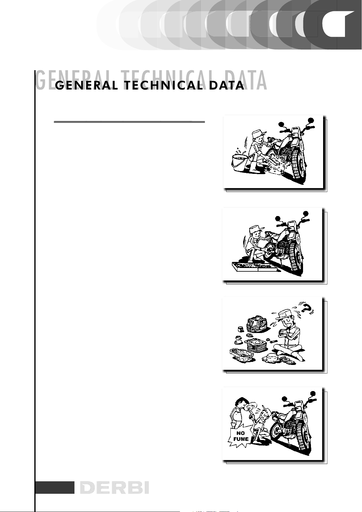
This section describes the machine’s general safety and maintenance work rules.
SAFETY REGULATIONS
In the event of having to carry out work on the engine while this is running, ensure that the area is well ven-
tilated, where possible using extractor fans. Never leave engines running in closed spaces. Exhaust gases
are poisonous.
Petrol is extremely inflammable and in certain conditions may explode. Smoking must not be allowed in the
work area, nor should there be naked flames or sparks.
MAINTENANCE REGULATIONS
- Use genuine DERBI spare parts and lubricants recommended by the Manufacturer. Non-genuine or unau-
thorised parts may damage the engine.
- Always use new gaskets and oil seals during re-assembly.
- After dismantling, clean the components with solvents that are non-inflammable or with a high flammability
point. Lubricate all working surfaces before re-assembling, excluding tapered joints.
- After re-assembly, check that all components have been correctly fitted and that they are functioning per-
fectly.
- For dismantling, checking and re-assembly operations, use only tools with metric measurements. Metric
screws, nuts and bolts are not interchangeable with imperial measurement joining devices. Using unsuitable
tools and joining devices may damage the engine.
- In the case of work on the engine involving the electrical circuitry, check that electrical connections have
been correctly fitted.
REGULATIONS
SAFETY
REGULATIONS
M
AINTENANCE
REGULATIONS

5
Use genuine DERBI spare parts and lubricants recommen-
ded by the Manufacturer. Non-genuine or unauthorised par-
ts may damage the machine.
Only use the specific tools intended for this machine.
During re-assembly, always use new seals, gaskets, piston
rings and grommets.
After dismantling, clean the components with solvents that
are non-inflammable or that have a high flammability point.
Grease all working surfaces before assembling, excluding
tapered joints.
After assembly, check that all components have been correc-
tly fitted and that they are functioning perfectly.
For dismantling, checking and re-assembly operations, use
only tools with metric measurements. Metric screws, nuts
and bolts are not interchangeable with imperial measure-
ment joining devices. Using unsuitable tools and joining de-
vices may damage the machine.
In the case of work on the machine’s electrical circuitry,
check that electrical connections have been correctly fitted,
especially the earth connections.
VEHICLE IDENTIFICATION
VEHICLE
IDENTIFICATION
VEHICLE
GPR 125 Racing
CHASSIS CODE ENGINE CODE
E1 19ExxxxxxVTHGS1A1A?Hxxxxxx

6
RACING 125 GENERAL TECHNICAL DATA
Engine
Diameter x stroke
Cylinder capacity
Carburettor
Cooling
Starting
RACING
125
GENERAL
TECHNICAL
DATA
Compression ratio
Maximum power
Fuel
Greasing system
Ignition
Spark plug
Primary transmission
Clutch
Front suspension
Rear suspension
Gears
Single cylinder 2-stroke EURO 2
56,0 x 50,7 mm
124,9 cm3
Mikuni TM 28-92
Liquid
Electric
12,5 : 1
11 kW (14.9 HP) / 8.000
Lead-free petrol
Wet crankcase
Ignition D.I.U-
NGK BR8ES
Gears
Multi-disk
40 mm Ø hydraulic fork. 110 mm travel
Single shock absorber. 14mm Ø rod. 110 mm travel
6 speed
Tyres 140/70 x 17”
Front disk brake
Rear disk brake
Battery
Distance between axles
Height
Length
Width
Fuel tank
300 mm hydraulic disk
180 mm Ø hydraulic disk
12 V 4 Ah
1.355 mm
1.160 mm
2.024 mm
720 mm
13 L.
7
PREPARATION FOR REMOVAL AND DISMANTLING
1. Remove all the dirt, grime, dust and other foreign material
before removing and dismantling.
2. Use proper cleaning tools and equipment.
See “SPECIAL TOOLS”.
3. On dismantling the motorcycle, always keep paired par-
ts together. This includes gears, cylinders, pistons and other
parts submitted to natural wear in pairs. Paired parts must
always be reassembled or replaced together.
4. While dismantling the motorcycle, clean all the parts and
lay them out on trays in the order dismantled. This speeds up
reassembly and ensures the correct fitting of all the parts.
5. Keep all parts away from any contact with fire.
PREPARATION
FOR
REMOVAL
AND
DISMANTLING

8
SPARE PARTS
1. Use only genuine DERBI spare parts. For all lubrication
tasks use oils and greases recommended by DERBI. Other
makes may seem similar in their function and appearance,
but are inferior in quality.
SEALS, RETAINING RINGS AND O-RINGS
1. Replace all seals, retaining rings and O-rings when servi-
cing the engine.
All surfaces receiving seals, retaining ring edges and O-rings
must be cleaned.
2. Apply oil to all paired parts and bearings during reassem-
bly. Apply grease to the retaining ring edges.
TAB WASHERS/SPACERS AND SPLIT PINS
1. After removing them, renew all tab/spacer washers (1)
and split pins. Bend the tabs to fit the flat surfaces of the
bolt or nut once they have been tightened to the specified
torque.
BEARINGS AND RETAINING RINGS
1. Fit bearings and retaining rings in such a way that the ma-
nufacturers marks remain visible. On fitting retaining rings,
applying a thin film of light lithium soap based grease to
their edges. Where required, apply oil generously when fit-
ting bearings.
WARNING
DO NOT USE COMPRESSED AIR TO DRY BEARINGS. THIS
WILL DAMAGE TO THE BEARING SURFACES.
SS
SEALS,
RETAINING
RINGS
AND
O RINGS
TAB
WASHERS/SPACERS
AND
SPLIT
PINS
GS GGS

9
LOCKING RINGS
1. Examine all the locking rings carefully before fitting.
Always replace the gudgeon pin circlips after every use. Re-
place distorted locking rings. On fitting a locking ring (1),
ensure that the sharp edge (2) is on the opposite side to the
force (3) to be applied to it.
See the figure on the side, (4) Axle.
SPECIAL TOOLS
The following special tools are needed for assembly and for
complete and exact adjustments. Only use the proper special
tools; thereby avoiding damage caused by the use of unsui-
table tools or improvised techniques.
1.00M12501258
Gudgeon pin extractor.
This tool is used for dismantling the gudgeon pin.
00M12501259
Magneto flywheel extractor.
This tool is used for dismantling the magneto flywheel.
LOCKING
RINGS
SPECIAL
TOOLS

10
3. 00M12501260
Clutch holder.
This tool is used to hold the clutch assembly when fitting or
dismantling its axle nut.
4. 00M12501261
Crankcase separator.
This tool is used to separate the crankshaft from the case.
4. 00H05100181
40 mm fork seal inserting tool
This tool is used for inserting the seals into the forks, as des-
cribed in the corresponding section.
11
GENERAL SPECIFICATIONS
GENERAL
SPECIFICATIONS
BASIC WEIGHT
With oil and full fuel tank
AIR FILTER
FUEL
Type
Fuel tank capacity
Reserve volume
Wet-type element
131 kg
TYPE OF FLUID
Engine oil
AGIP CITY 2-stroke API SJ « DONUT» + JASO MA - PART
SYNTHETIC oil, SAE Viscosity: SAE 10W30 or higher
OIL CAPACITY
Engine oil.
Regular oil change.
Total capacity
0,75 L.
0,8 L.
Lead free petrol (95 octane or higher)
12 L.
2 L.
MODEL GPR 125 Racing
CARBURETTOR
Type
Manufacturer
TM 28-92/1
MIKUNI
SPARK PLUG
Type / Manufacturer
Gap between the electrodes
NGK BR8ES
0.7 mm.
CLUTCH TYPECLUTCH TYPE Wet, multi-disk.
TRANSMISSION
Primary reduction system
Primary reduction ratio
Secondary reduction system
Secondary reduction ratio
Type of transmission
Operation
Gear ratio
1
2
3
4
5
6
Helicoidal gears
71/22 (3.227)
Transmission chain
57/16 (3.563)
Constant gearing, 6 speed
With the left foot
34/12 (2.883)
30/16 (1.875)
24/17 (1.412)
24/21 (1.143)
22/23 (0.957)
18/22 (0.818)
CHASSIS
Frame type
Caster angle
Trail
Delta Box
26.4º
109 mm.

12
MODEL GPR 125 Racing
NEUMÀTICOSTYRES
Size
Front
Rear
Tubeless
110/80 – 17 “
140/70 – 17”
TYRE PRESSURES (COLD)
Rider only
Front
Rear
Rider and passenger
Front
Rear
170 kPa (1,7 kg/cm2)
190 kPa (1,9 kg/cm2)
190 kPa (1,9 kg/cm2)
210 kPa (2,1 kg/cm2)
FRENO
Front brake
Type
Operation
Front brake
Type
Operation
300 mm Ø disk. VENTILATED
With the right hand
180 mm Ø disk. VENTILATED
With the right foot
SUSPENSION
Front suspension
Rear suspension
Hydraulic fork
Swnging arm + hydraulic shock absorber
SUSPENSION TRAVEL
Front
Rear
110 mm
110 mm
ELECTRICAL SYSTEM
Ignition system
Charging system
Battery type
Battery capacity
DIU
Magneto flywheel
Yuasa MF YTX5L-BS
12v 4Ah
BULB VOLTAGE AND WATTAGE PER QUANTITY
Headlight
Frontt side-light
Rear side/brake light
Front turn indicators
Rear turn indicators
12v 35W dip H11
12v 35W main beam H11
12v 2.3W
12v 2,3W/16W
12v 10Wx2
12v 2.3Wx2
INDICATOR LIGHTS
Water temperature indicator
Oil indicator
Fuel indicator
Main beam indicator
Turn indicators pilot light
LED
LED
LED
LED
LED

13
ENGINE SPECIFICATIONS
ENGINE
SPECIFICATIONS
CYLINDER HEAD
<Distortion limit> <0,03 mm>
* The lines indicate measurement at a right angle
CYLINDER
Diameter 56,00 ~ 56,02 mm
MODEL GPR 125 Racing
Conicity limit
Ovality limit
0,05 mm
0,01 mm
PISTON
Cylinder-piston play
<Limit>
Diameter of piston “D”
Measurement point “H”
Piston off-set
0.045 ÷ 0.050 mm
<0.10 mm>
55.950 ÷ 55.955 mm
10 mm
0,5 mm
PISTON RINGS
Top ring:
Type
Dimensions (BxT)
Top ring (ignition)
Bottom ring
Gap between points (fitted)
Top ring
Bottom ring
Side play (fitted)
Top ring
Bottom ring
Keystone
1.2 x 2.4 mm
1.2 x 1.89 mm
0.300 ÷ 0.450 mm
0.300 ÷ 0.450 mm
0.020 ÷ 0.060 mm
0.035 ÷ 0.070 mm
T
B
CRANKSHAFT
Width “A”
<Warp limit “C”>
Connecting rod bottom play “D”
< Connecting rod top play limit “F”>
57.90 ÷ 57.95 mm
<0.03 mm>
0.2 ÷ 0.7 mm
<0.026 ÷ 0.040 mm>

14
MODEL GPR 125 Racing
CLUTCH
Thickness of friction disks
Quantity
<Friction disk wear limit>
Thickness of the separators
Quantity
<Distortion limit>
Free length of clutch spring
Quantity
Minimum length
Clutch freeing method
Actioning rod warp limit
2.9 ÷ 3.1 mm
7 parts
2.7 mm
1.05 ÷ 1.35 mm
6 parts
0.05 mm
34.5 mm
5 parts
32 mm
Internal by lever system
<0.15 mm>
GEAR SELECTOR
Type Selector and guide bar
CARBURETTOR
Type
ID mark
Main jet
Main pneumatic jet
Jet needle
Needle jet
Pilot outlet
Pilot jet
Bypass1
Pilot screw (turns)
Valve seat size
Choke jet 1
Choke jet 2
Float height
Chamber level
Engine idle speed
TM 28-92/1
1 DO
#210
0.7
5J40 – 2
Q2M (#939)
0.6
#17.5
1.6
¼
2.8
#40
#60
15.5 ÷ 16.5 mm
1.5 ÷ 2.5 mm
1250 ÷ 1450 rpm
LUBRICATION SYSTEM
Colour code
Minimum run
Maximum run
Minimum output
Maximum output
Pulley adjustment mark
Dark blue
0.15 ÷ 0.20 mm
1.85 ÷ 2.05 mm
0.38 ÷ 0.50 cm3
4.65 ÷ 5.15 cm3
Self-adjusting
REED VALVE
Valve thickness
Stop plate heigh
Valve bend limit
0.5 mm
8.8 mm
0.5 mm

15
PARTS TO BE TIGHTENED
TIGHTENING TORQUE
m.Kg
Nm
OBSERVATIONS
Spark plug
Cylinder LOCTITE
bolt securing
adhesive
Cylinder head Cap nuts
Stud bolt
Nut
ENGINE TIGHTENING TORQUES
Exhaust valve support, valve
cover
Seal
Stud
Exhaust valve pulley Stud
Thermostat valve cover Bolt
Water pump cover
AMNT.
1
5
9
4
6
3
2.0
2.2
1.3
2.8
0.7
1.0
0.8
20
22
13
28
7
10
8
Bolt
Water drain bolt
THREAD
SIZE
M14 x 1.25
M8 x 1.25
M8 x 1.25
M8 x 1.25
M5 x 0.8
M6 x 1.0
M6 x 1.0
2
1
0.8
1
8
10
M6 x 1.0
M6 x 1.0
Radiator Stud 20.88M6 x 1.0
Radiator cover Bolt 10.55M5 x 0.8
Oil pump Bolt 20.55M5 x 0.8
Carburettor gasket Stud 40.88M6 x 1.0
Air filter Bolt 20.55M6 x 1.0
Silencer Nut
Stud bolt
Stud
2
2
3
1.8
1.0
0.8
18
10
8
M8 x 1.25
M8 x 1.25
M6 x 1.0
LOCTITE
bolt securing
adhesive
Oil change drain plug
11.515M8 x 1.25
Left hand crankcase cover
Bolt 60.55M6 x 1.0
Right hand crankcase cover Bolt 60.88M6 x 1.0
Oil pump cover
Bolt 30.55M6 x 1.0
Crankcase
Bolt 12 0.88M6 x 1.0
Oil seal support
Bolt 11.616M8 x 1.25
Cover
Bolt 20.88M6 x 1.0
Clutch housing
Nut 1770M12 x 1.0
Clutch spring
Stud 50.66M5 x 0.8
Clutch disk cover
Bolt 2110M6 x 1.0

16
PARTS TO BE TIGHTENED
TIGHTENING TORQUE
m.Kg
Nm
OBSERVATIONS
Drive sprocket
Tachometer cog housing Stud
Rotor
AMNT.
1
1
6
0.5
60
5
Nut
THREAD
SIZE
M6 x 1.0
M6 x 1.0
1
1
1.5
8
15
80M12 x 1.25
Nut
Stop lever Stud 11.414M6 x 1.0 LOCTITE
bolt securing
adhesive
Change pedal Stud 11.515M6 x 1.0
Starter motor

17
MODEL GPR Racing 125 c.c.
STEERING SYSTEM
Type of steering bearing
FRONT SUSPENSION
Free length of forks spring
<Limit>
Spring strength
Travel
Oil/bar capacity
Type of oil
Rigid ball bearing
851 mm
845 mm
20 N/mm
110 mm
340 cm3
FSAE 7.5W fork oil or higher
REAR SWINGING ARM
<Play limit> At the end
At the side
<1,0 mm>
<1,0 mm>
REAR SUSPENSION
Shock absorber travel
Free length of spring
Length of spring fitted
Spring strength
34 mm
140 mm
130 mm
100 N/mm (0<32 mm)
170 N/mm (32<50 mm)
FRONT WHEEL
Type
Wheel size
Wheel material
<Wheel distortion limit>
Radial Side
Injected metal
17”
Aluminium alloy
<0.5 mm>
<0.5 mm>
REAR WHEEL
Type
Wheel size
Wheel material
<Wheel distortion limit>
Radial Lateral
Injected metal
17”
Aluminium alloy
<0.5 mm>
<0.5 mm>
DRIVE CHAIN
Number of links
ChaIn play.
130
11 mm

18
MODEL GPR Racing 125 c.c.
FRONT DISK BRAKES
Type
Disk width
<Wear limit>
Brake pad thickness
<Wear limit>
VENTILATED hydraulic disk
4.0 mm
3.5 mm
4.5 mm
1.5 mm
LEVERS AND TWISTGRIP
Brake lever clearance
(at the end)
Clutch lever clearance
(at the end)
Throttle twist grip clearance
10 ~ 15 mm
10 ~ 15 mm
2 ÷ 6 mm
REAR DISK BRAKES
Type
Inner diameter of brake drum
<Wear limit>
Brake shoe thickness
<Wear limit>
VENTILATED hydraulic disk
4.0 mm
3.5 mm
4.5 mm
1.5 mm

19
MODEL GPR 125 Racing
VOLTAGE
Ignition system:
Ignition point (B.T.D.C)
Advance type
12V
17 º a 1.500 rpm
Digital
IGNITION COIL
Model
Primary winding resistance
Secondary winding resistance
3RW/YAMAHA
0.23 Ω ± 20%
7.9 k Ω ± 20%
DIU
Model of magneto/manufacturer
Detector coil resistance
Generator coil resistance
Generator coil resistance
Model of DIU/manufacturer
F4FU/YAMAHA
310 Ω ± 20% W/R-W/L
730 Ω ± 20% B/R-G/W
600 Ω ± 20% G/L-G/W
1D0/YAMAHA
SPARK PLUG CONNECTOR
Type
Resistance
Resin
5KΩ ± 20% a 20º C
CHARGING SYSTEM
Type
Magneto flywheel Model/Manufacturer
Output
Charging coil resistance
(colour of the conductors)
Magneto
F4FU / YAMAHA
14V 170 W 5000 rpm
0.6Ω ± 20% a 20º C W-W
LIGHTING VOLTAGE (Min)
(Max)
12V / 3.000 rpm
15V / 8.000 rpm
RECTIFIER/ REGULATOR
Type
Model
Voltage regulated without charge
Capacity
Resistance limit voltage
Shortcircuit type semiconductor
SH629B-11/SHINDENGEN
14.1 ~ 14.9 V
25 A
200 V
Other manuals for GPR 125 Racing
1
Table of contents
Other Derbi Motorcycle manuals

Derbi
Derbi SENDA R DRD PRO 50 c.c. User manual

Derbi
Derbi SENDA 50 DRD RACING X-TREME User manual

Derbi
Derbi Dirtboy 10 Instruction manual

Derbi
Derbi GPR 50 2009 User guide

Derbi
Derbi GP1 50 cc Instruction manual

Derbi
Derbi X-TREME R/SM User manual

Derbi
Derbi GPR 125 Racing Instruction manual

Derbi
Derbi Senda DRD Evo 50 SM User manual

Derbi
Derbi RAMBLA 250 i.e. 2008 User manual

Derbi
Derbi SENDA R/SM 125 4T Baja User manual


 Owner's service manual")


