Derbi GP1 50 cc Instruction manual

GP150 cc
WORKSHOP MANUAL

1
DERBI - NACIONAL MOTOR, S.A., manufacturer of DERBI motorcycles and mopeds, has produced this
manual with the aim of documenting and simplifying as much as possible the work you need to do to in dis-
mantling and assembling the GP1 50 c.c.
The intention is to provide as much assistance as possible to mechanics working for our brand’s dealers and
sub-dealers.
Due to its constant commitment to improving its products, DERBI - NACIONAL MOTOR, S.A. Sociedad
Unipersonal reserves the right to introduce any modifications it deems fit, without prior warning.
All the information included in this manual is based on the latest data available at the time of its publication.
The drawings and photographs in this manual are for reference purposes only, and may therefore not be
exactly the same as the corresponding parts of the current model itself.
NACIONAL MOTOR, S.A.


3
INTRODUCTION
GENERAL INFORMATION
GENERAL TECHNICAL DATA
RECOMMENDED TOOLS
REGULAR MAINTENANCE
DISMANTLING
SEAT SIDE TRIM
COWLING
COWLING BOTTOM COVER
WATER-OIL TANK COVER
SIDE COVERS
SHIELD BOTTOM COVER
PETROL TANK COVER
HELMET HOLDER
FOOTRESTS
SIDE COVERS
SHIELD
DIRECT ACCESS TO THE BOTTOM OF THE CARBURETTOR
DISMANTLING FOOTRESTS
EXTRACTING COMPLETE AIR FILTER BOX
DISCONNECTING SECONDARY AIR PIPE
EXTRACTING CARBURETTOR AIR INTAKE PIPE
EXTRACTING CARBURETTOR
THE MACHINE’S ENGINE
DISMANTLING THE ENGINE
TRANSMISSION COVER
DISMANTLING DRIVEN PULLEY SHAFT SUPPORT BEARINGS
FITTING DRIVEN PULLEY SHAFT SUPPORT BEARINGS
DISMANTLING DRIVEN PULLEY
CHECKING CLUTCH BELL HOUSING
DISMANTLING CLUTCH
CHECKING CLUTCH
BRAKE RETAINING RING
DISMANTLING DRIVEN PULLEY HALF BEARINGS
CHECKING FIXED DRIVEN HALF PULLEY
CHECKING MOBILE DRIVEN HALF PULLEY
FITTING DRIVEN HALF PULLEY BEARINGS
CHECKING VARIATOR SPRING
Page 1
Page 8
Page 9
Page 18
Page 24
Page 35
Page 35
Page 36
Page 36
Page 36
Page 37
Page 37
Page 38
Page 39
Page 39
Page 39
Page 40
Page 40
Page 40
Page 40
Page 41
Page 43
Page 43
Page 44
Page 44
Page 45
Page 45
Page 45
Page 46
Page 46
Page 47
Page 47
Page 48
Page 49
Page 49

4
ASSEMBLING CLUTCH
FITTING DRIVEN PULLEY
TRANSMISSION BELT
DISMANTLING DRIVING PULLEY
MIXER GEARING AND BELT
CHECKING ROLLER CONTAINER
FITTING DRIVING PULLEY
FINAL REDUCTION
DISMANTLING ENGINE PINION
DISMANTLING HUB COVER
DISMANTLING OUTPUT PINION SHAFT
DISMANTLING OUTPUT PINION SHAFT BEARING
DISMANTLING DRIVEN PULLEY SHAFT BEARING
CHECKING THE HUB SHAFTS
CHECKING THE HUB COVER
FITTING DRIVEN PULLEY SHAFT BEARING
FITTING WHEEL PULLEY SHAFT BEARING
FITTING THE HUB COVER
MAGNETO COVER
DISMANTLING THE ENGINE
FITTING THE STATOR
FITTING THE MAGNETO COVER
MAGNETO AND STARTING
DISMANTLING THE STARTER MOTOR
DISMANTLING THE MAGNETO
CHECKING THE MAGNETO COMPONENTS
FITTING THE MAGNETO
FITTING THE STARTER MOTOR
CYLINDER UNIT AND TIMING
DISMANTLING THE SUCTION COLLECTOR
DISMANTLING THE CYLINDER HEAD
DISMANTLING THE PISTON CYLINDER
CHECKING THE CONNECTING ROD BIG END
CHECKING THE GUDGEON PIN
CHECKING THE PISTON
CHECKING THE CYLINDER
Page 49
Page 50
Page 50
Page 51
Page 51
Page 51
Page 52
Page 53
Page 53
Page 54
Page 54
Page 54
Page 55
Page 55
Page 55
Page 56
Page 57
Page 57
Page 57
Page 58
Page 58
Page 58
Page 59
Page 59
Page 60
Page 60
Page 60
Page 61
Page 61
Page 61
Page 62
Page 62

5
CHECKING THE OIL SEALS
FITTING THE PISTON
CHECKING TIMING COMPONENTS
CRANKCASE
OPENING THE CRANKCASE
DISMANTLING THE CRANKSHAFT
DISMANTLING THE MAIN BEARINGS
FITTING THE MAIN BEARINGS
CHECKING THE CRANKSHAFT ALIGNMENT
FITTING THE CRANKSHAFT
REJOINING THE CRANKCASE
LUBRICATION
OIL PUMP
DISMANTLING
FITTING
FUEL SUPPLY
FORKS
SEBAC FORKS
MARZOCCHI FORKS
DISMANTLING THE FRONT SUSPENSION
INSPECTING THE FRONT FORKS
SHOCK ABSORBER AND SWINGING ARM
SHOCK ABSORBER AND SWINGING ARM
DISMANTLING
INSPECTION
FRONT WHEEL AND BRAKES
FRONT WHEEL DIAGRAM
DISMANTLING
INSPECTING THE FRONT WHEEL
DISMANTLING THE FRONT DISK CALLIPER
FITTING THE FRONT WHEEL
Page 63
Page 63
Page 64
Page 65
Page 65
Page 65
Page 66
Page 67
Page 67
Page 68
Page 69
Page 70
Page 70
Page 71
Page 72
Page 73
Page 74
Page 76
Page 78
Page 79
Page 79
Page 80
Page 81
Page 81
Page 83
Page 90

6
REAR WHEEL AND BRAKES
REAR WHEEL DIAGRAM
DISMANTLING
DISMANTLING THE REAR DISK CALLIPER
INSPECTING THE REAR WHEEL
REFITTING THE REAR WHEEL
TRANSMISSION
DISMANTLING
INSPECTING THE TRANSMISSION CHAIN
CROWN WHEEL
REFITTING THE CROWN WHEEL AND THE TRANSMISSION CHAIN
COOLING SYSTEM
BLEEDING THE SYSTEM
CHECKING THE WATER PUMP
THERMOSTAT
DISMANTLING
CHECKING
FITTING
ELECTRICAL SYSTEM
GP1 50C.C. WIRING DIAGRAM
GP1 50C.C. WIRING DIAGRAM (SWITZERLAND)
CHECKING CONNECTORS
STEPS FOR THE INSPECTION
DIGITAL INSTRUMENTS UNIT
IGNITION
AUTOMATIC CHOKE AND LIGHTS
BATTERY RECHARGE AND STARTING
LEVEL INDICATORS
TURN INDICATORS AND HORN
CHECKS AND CONTROLS
CHECKING PICK-UP
REFITTING IGNITION
Page 91
Page 92
Page 92
Page 99
Page 99
Page 100
Page 101
Page 101
Page 102
Page 103
Page 103
Page 106
Page 106
Page 106
Page 107
Page 108
Page 109
Page 110
Page 111
Page 111
Page 112
Page 113
Page 114
Page 115
Page 116
Page 117
Page 117
Page 118

7
CHECKING THE STATOR
CHECKING THE VOLTAGE REGULATOR
OPERATIONS
FUSES
DISMANTLING THE BATTERY
BATTERY-INITIAL CHARGE
CAPACITY
INSPECTING THE CHARGING CONDITIONS
RECHARGING
CHECKING THE ELECTRICAL SYSTEM
TROUBLESHOOTING
ENGINE
REAR WHEEL TURNS WITH ENGINE TICKING OVER
DIFFICULTY STARTING
EXCESSIVE CONSUMPTION OF OIL/SMOKY EXHAUST
THE ENGINE TENDS TO STOP AT FULL THROTTLE
THE ENGINE TENDS TO STOP WHEN TICKING OVER
HIGH FUEL CONSUMPTION
EXCESSIVELY NOISY EXHAUST
ENGINE OVERHEATING
FAULTS
TRANSMISSION AND BRAKES PULLING OR ABNORMAL CLUTCH OPERATION
POOR BRAKING POWER
BRAKES OVERHEATING
ELECTRICAL WIRING
STEERING AND SUSPENSION – REAR WHEEL
STIFF STEERING
TOO MUCH PLAY IN STEERING
NOISY SUSPENSION
SUSPENSION LEAKING OIL
Page 118
Page 118
Page 119
Page 122
Page 122
Page 124
Page 124
Page 125
Page 126
Page 127
Page 128
Page 129
Page 129
Page 130
Page 130
Page 130
Page 131
Page 131
Page 131
Page 132
Page 132
Page 133
Page 133
Page 134
Page 134
Page 135
Page 135
Page 135
Page 136

8
REGULATIONS
This section describes the machine’s general safety and maintenance work rules.
SAFETY REGULATIONS
- In the event of having to carry out work on the engine while this is running, ensure that the area is well
ventilated, where possible using extractor fans. Never leave engines running in closed spaces. Exhaust gases
are poisonous.
Petrol is extremely inflammable and in certain conditions may explode. Smoking must not be allowed in the
work area, nor should there be naked flames or sparks.
MAINTENANCE REGULATIONS
- Use genuine DERBI spare parts and lubricants recommended by the manufacturer. Non-genuine or unau-
thorised parts may damage the engine.
Always use new gaskets and oil seals during re-assembly.
After dismantling, clean the components with solvents that are non-inflammable or with a high flammability
point. Lubricate all working surfaces before assembling, excluding tapered joints.
After assembly, check that all components have been correctly fitted and that they are functioning perfectly.
For dismantling, checking and assembly operations, use only tools with metric measurements. Metric screws,
nuts and bolts are not interchangeable with imperial measurement joining devices. Using unsuitable tools
and joining devices may damage the engine.
- In the case of work on the engine involving the electrical circuitry, check that electrical connections have
been correctly fitted.
N.B.
Indicates a note that gives key information to make the procedure easier and clearer.
ATTENTION
Indicates specific procedures that must be carried out to avoid damage to the machine.
WARNING
Indicates specific procedures that must be followed to avoid possible accidents to the person repairing the
machine.
GU O S
SGUOS
MAINTENANCE
REGULATIONS

9
CHARACTERISTIC DIMENSION/VALUE
Maximum length
Maximum height
Length between axles
Handlebar width
Handlebar height
Total weight of machine
GP1 50 c.c. C451M
GP1
50
c.c.
MACHINE ENGINE PREFIX FRAME PREFIX
VTHPR1A1A
DIMENSIONS AND WEIGHT
1875 mm.
1212 mm.
1338 mm.
705 mm.
1050 mm.
117 kg.
CHARACTERISTIC DIMENSION/VALUE
Engine type
Diameter per stroke
Cubic capacity
Compression ratio
Carburettor
CO regulation
Tick over
Air filter
Ignition system
Lubrication
ENGINE
Single cylinder 2-stroke
40 x 39.3 mm
49.40 cm3
11.3 ÷ 12.8 :1
DELL’ORTO PHVA 17,5 ID
3.5%±0.5
1800 ÷ 2000 rpm
Sponge soaked in oil for filters.
Electric starter motor.
Carried out using the mixture oil, and variable depen-
ding on the engine revs and the throttle butterfly valve
aperture by means of a pump driven by the crankshaft
by way of a toothed belt.
10
Fuel tank capacity
Fuel reserve capacity
Oil tank capacity
Oil reserve capacity
Cooling system capacity
7.7 l
2.7 l
1.75 l
0.25 l
1.0 l
CHARACTERISTIC DIMENSION/VALUE
Alimentación
Sistema de refrigeración
Embrague
Piñón salida cambio
Plato de arrastre
ENGINE
By forced circulation of liquid.
Dry automatic centrifugal
Z 19
Z 45
Depression fuel pump supplying lead free petrol via the
carburettor.
CHARACTERISTIC DIMENSION/VALUE
Transmission
TRANSMISSION
Automatic speed variator with expandable pulleys, tra-
pezoidal belt, automatic clutch, gear reducer.
CHARACTERISTIC DIMENSION/VALUE
CAPACITY
CHARACTERISTIC DIMENSION/VALUE
Ignition system
Ignition advance (before T.D.C.)
Spark plug
Battery
Main fuse
ELECTRICAL SYSTEM
17º a 4000 rpm
CHAMPION RN1C
12 V 6 Ah
7.5 A
Electronic 12v 88 W with central intermittence unit +
check control

11
Frame
Front suspension
Diameter / Travel
Oil capacity
Oil type
Rear suspension
Travel
Aluminium, Delta Box type
Telescopic forks with inverted bars
35 mm / 80 mm
95 c.c.
SAE 7,5 W
Swinging arm with single shock absorber.
80 mm
CHARACTERISTIC DIMENSION/VALUE
FRAME AND SUSPENSIONS
Front brake
Front disk diameter
Rear brake
Rear disk diameter
Brake fluid type
Hydraulically operated disk
245 mm
Hydraulically operated disk
180 mm
DOT 4
CHARACTERISTIC DIMENSION/VALUE
BRAKING SYSTEM
Front wheel type
Front tyre inflated pressure.
Rear wheel type
Rear tyre inflated pressure
120 / 70 x 14in (tubeless)
190 kPa / 200 kPa (with pillion passenger)
140 / 60 x 14in (tubeless)
200 kPa / 220 kPa (with pillion passenger)
CHARACTERISTIC DIMENSION/VALUE
WHEELS AND TYRES
Type
Diameter of diffuser
Main jet
Minimum air jet
Carburettor needle setting
Needle position (slots from above)
DELL’ORTO PHVA 17.5 ID
Ø 17.5 mm
53
Ø 1.5 mm
A22
1
CHARACTERISTIC DIMENSION/VALUE
CARBURETTOR

12
Emulsifier
Idle jet
Minimum air jet
Secondary minimum air orifice
Minimum mixture screw initial opening
Choke jet
Choke air jet
Choke needle travel
Fuel entry orifice
209HA
32
Libre
Ø 2.5 mm
1 1/2
50
Ø 1.5 mm
11 mm
Ø 1.0 mm
CHARACTERISTIC DIMENSION/VALUE
CARBURETTOR
13
CHASSIS TIGHTENING TORQUES
Top shock absorber - chassis securing device M10x150 8.8
Bottom shock absorber – engine securing device M10x150 8.8
Engine Silent bloc – chassis securing device M10x150 8.8
Engine support securing bolt M10x150 8.8
Engine rear – support securing device M8x125 8.8
Engine rear support - chassis securing device M10x150 8.8
Engine rear Silent bloc clamp securing device M6x100 8.8
Swinging arm securing device M14x200
Change output pinion bush securing device M16x125
Change output pinion securing device M35x100
Filter box – engine securing device M6x100
Horn – chassis securing device M6x100
Steering forks – chassis securing device M24x100
Exhaust pipe –cylinder securing device M6x100 8.8
Exhaust pipe –crankcase securing device M8x125 8.8
Steering lock – chassis securing device M6x100 8.8
Handlebars – steering forks securing device M6x100 8.8
Handlebar clamp securing device M8x125 8.8
Counterweight- handlebars securing device M5x80 8.8
Front wheel – forks securing device M14x200
Fork arm lock securing device M8x125
Brake disk – front wheel securing device M6x100
Brake disk calliper – forks securing device M10x1.5
Rear wheel securing device M14x200
Drag plate – wheel securing device M6x100 10.9
Brake disk – rear wheel securing device M8x125 10.9
Prop stand – chassis securing device M8x125
Brake puller securing device M10x150 10.9
Gripper – chassis securing device M8x125 8.8
Radiator - chassis securing device M6x100
Various metal elements to chassis securing device M5x80
Various metal elements to chassis securing device M6x100
Various metal elements to chassis securing device M8x125
Various plastic elements to chassis securing device M6x100
Various plastic elements to chassis securing device M6x100
30 ÷ 40
30 ÷ 40
30 ÷ 40
20 ÷ 30
17 ÷ 19
30 ÷ 40
8 ÷ 10
70 ÷ 80
115 ÷ 125
115 ÷ 125
8 ÷ 10
8 ÷ 10
90 ÷ 130
9 ÷ 12
17 ÷ 19
8 ÷ 10
17 ÷ 19
17 ÷ 19
3.5 ÷ 4.5
35 ÷ 50
15 ÷ 19
8 ÷ 10
35 ÷ 40
70 ÷ 80
10 ÷ 12
25 ÷ 29
15 ÷ 19
35 ÷ 40
17 ÷ 19
8 ÷ 10
3.5 ÷ 4.5
8 ÷ 10
15 ÷ 19
1 ÷ 2
2 ÷ 3.5
DESCRIPTION TORQUES (N.M)
3 ÷ 4
3 ÷ 4
3 ÷ 4
2 ÷ 3
1.7 ÷ 1.9
3 ÷ 4
0.8 ÷ 1
7 ÷ 8
11.5 ÷ 12.5
11.5 ÷ 12.5
0.8 ÷ 1
0.8 ÷ 1
9 ÷ 13
0.9 ÷ 1.2
1.7 ÷ 1.9
0.8 ÷ 1
1.7 ÷ 1.9
1.7 ÷ 1.9
0.35 ÷ 0.45
3.5 ÷ 5
1.5 ÷ 1.9
0.8 ÷ 1
3.5 ÷ 4
7 ÷ 8
1 ÷ 1.2
2.5 ÷ 2.9
1.5 ÷ 1.9
3.5 ÷ 4
1.7 ÷ 1.9
0.8 ÷ 1
0.35 ÷ 0.45
0.8 ÷ 1
1.5 ÷ 1.9
0.1 ÷ 0.2
0.2 ÷ 0.35
TORQUES (M.KG)
•
•
•
•
•
•
SEALER
14
12 ÷ 13
8 ÷ 9
1 ÷ 2
3.5 ÷ 5
3 ÷ 4
4 ÷ 5
3 ÷ 4
12 ÷ 13
ENGINE TIGHTENING TORQUES
Clutch bell housing nut
Clutch locking nut
Nut for locking the driving pulley on the crankshaft
Kick start lever bolt
Magneto nut
Magneto fan bolts
Crankcase halves joining bolts
Bolts for securing exhaust pipe to the crankcase
Bolts for securing the filter box to the crankcase
Cylinder head nuts
Starter motor bolts
Spark plug
Oil sump drain plug
Rear hub cover bolts
DESCRIPTION TORQUES (N.M) TORQUES (M.KG)
40 ÷ 44
55 ÷ 60
40 ÷ 44
12 ÷ 13
40 ÷ 44
3 ÷ 4
12 ÷ 13
22 ÷ 24
4 ÷ 5
10 ÷ 11
12 ÷ 13
25 ÷ 30
3 ÷ 5
12 ÷ 13
4 ÷ 4.4
5.5 ÷ 6
4 ÷ 4.4
1.2 ÷ 1.3
4 ÷ 4.4
0.3 ÷ 0.4
1.2 ÷ 1.3
2.2 ÷ 2.4
0.4 ÷ 0.5
1 ÷ 1.1
1.2 ÷ 0.3
2.5 ÷ 3
0.3 ÷ 0.5
1.2 ÷ 1.3
DESCRIPTION TORQUES (N.M) TORQUES (M.KG)
1.2 ÷ 1.3
0.8 ÷ 0.9
0.1 ÷ 0.2
0.35 ÷ 0.5
0.3 ÷ 0.4
0.4 ÷ 0.5
0.3 ÷ 0.4
1.2 ÷ 1.3
Transmission cover bolts
Suction collector bolts
Magneto cover securing bolts
Cylinder casing securing bolts
Stator securing bolt
Pick-up securing bolt
Mixer securing bolt
Bolt securing brake pedal to shaft in the engine

15
CONECTION PISTON AND CYLINDER
Standard fitting
Standard fitting
Standard fitting
Standard fitting
1st oversize fitting
1st oversize fitting
1st oversize fitting
1st oversize fitting
2nd oversize fitting
2nd oversize fitting
2nd oversize fitting
2nd oversize fitting
NAME PLAY
<⁄>
<⁄>
<⁄>
<⁄>
<⁄>
<⁄>
<⁄>
<⁄>
<⁄>
<⁄>
<⁄>
<⁄>
INITIALS
M
N
O
P
M1
N1
O1
P1
M2
N2
O2
P2
CYLINDER
39,997-40,004
40,004-40,011
40,011-40,018
40,018-40,025
40,197-40,204
40,204-40,211
4,211-40,218
40,218-40,225
40,397-40,404
40-404-40,411
40-411-40,418
40,418-40,425
PISTON
39,943-39,95
39,95-39,957
39,957-39,964
39,964-39,971
40,143-40,15
40,15-40,157
40,157-40,164
40,164-40,171
40,343-40,35
40,35-40,357
40,357-40,364
40,364-40,371
PLAY ON FITTING
0,047-0,061
0,047-0,061
0,047-0,061
0,047-0,061
0,047-0,061
0,047-0,061
0,047-0,061
0,047-0,061
0,047-0,061
0,047-0,061
0,047-0,061
0,047-0,061
PISTON RINGS
Compression lining
Compression lining 1˚ Greater
Compression lining 2˚ Greater
NAME DIMENSIONS
40
40,2
40,4
INITIALS
A
A
A
QUANTITY
0,10 ÷ 0,25
0,10 ÷ 0,25
0,10 ÷ 0,25
DESCRIPTION

16
END PLAY BETWEEN CRANKCASE, CRANKSHAFT AND CONNECTING ROD
Connecting rod
Packing washer
Half shaft transmission side
Half shaft flywheel side
Spacing between shoulders
Cage
NAME DIMENSIONS
11,750 ÷ 0,05
0,5 ÷ 0,03
13,75 ÷ 0,040
13,75 ÷ 0,040
40,64
11,80 ÷ 0,35
INITIAL
A
G
C
D
H
B
C
onnectin
g
rod
P
ac
ki
ng was
h
er
Ha
lf
s
h
a
ft tr
a
n
s
mi
ss
i
o
n
s
i
de
H
alf shaft fl
y
wheel sid
e
S
pac
i
ng
b
etween s
h
ou
ld
ers
C
a
ge
QUANTITY
Play E=0,25÷0,50
Play F= 2,20÷0,75
DESCRIPTION
Play E=0,25÷0,50
Play F= 2,20÷0,75
Play E=0,25÷0,50
Play F= 2,20÷0,75
Play E=0,25÷0,50
Play F= 2,20÷0,75
Play E=0,25÷0,50
Play F= 2,20÷0,75
Play F= 2,20÷0,75
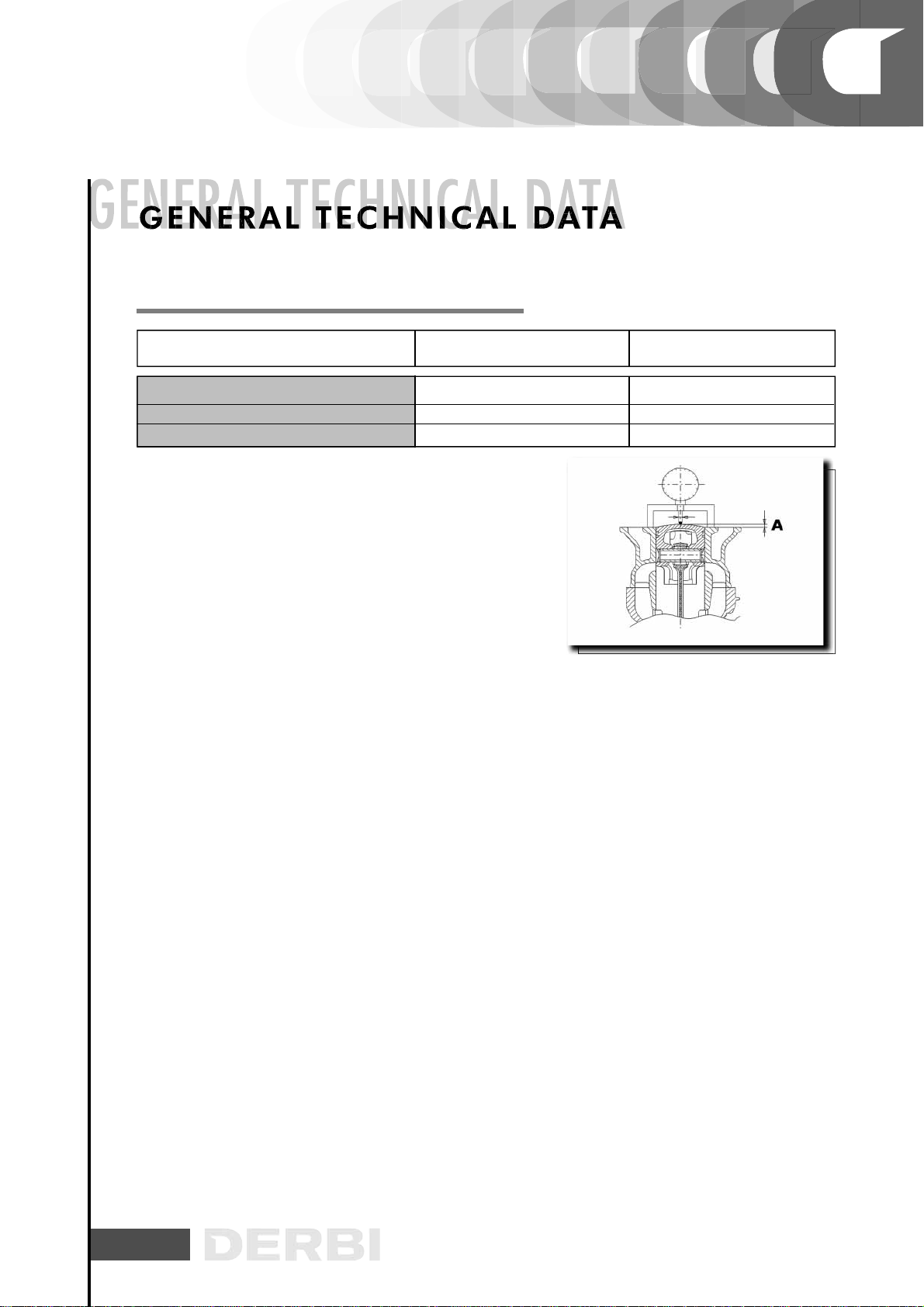
SLOT PACKING SYSTEM
- Fit the cylinder without positioningthe base gasket
- Position a dial gauge on the special tool and zeri it on rectified surface.
- Fis the tool on the top of the cylinder using two nuts to fix it to the studs and then bring the piston to T.D.C.
- The gasket thickness to be adopted varies with the measurement. For this reason gaskets with three diffe-
rent thicknesses ara available as spares.
Specific tooling
020272Y Tool for checking the piston of the piston.
S
LOT
PACKING
S
YSTEM
17
SISTEMA DE MONTAJE DE ESPESORES
Packing
Packing
Spacing
NAME THICKNESS
0,4
0,6
0,8
MEASURE A
2,80 ÷ 3,04
3,04 ÷ 3,24
3,24 ÷ 3,48

18
PPREPARATION FOR REMOVAL AND DISMANTLING
1. Remove all the dirt, grime, dust and other foreign material
before removing and dismantling.
2. Use properly cleaned tools and equipment.
See “SPECIAL TOOLS”.
3. On dismantling the motorcycle, always keep paired parts
together. This includes gears, cylinders, pistons and other
parts submitted to natural wear in pairs. Paired parts must
always be reassembled or replaced together.
4. While dismantling the motorcycle, clean all the parts and
lay them out on trays in the order dismantled. This speeds up
reassembly and ensures the correct fitting of all the parts.
5. Keep all parts away from any contact with fire.
P
PREPARATION
FOR
REMOVAL
AND
DISMANTLING

19
REPLACEMENT PARTS
1. Use only genuine DERBI spare parts. For all lubrication
tasks use oils and greases recommended by DERBI. Other
makes make seem similar in their function and appearance,
but are inferior in quality.
SEALS, RETAINING RINGS AND O-RINGS
1. Replace all seals, retaining rings and O-rings when servi-
cing the engine.
All surfaces receiving seals, retaining ring edges and O-rings
must be cleaned.
2. Apply oil to all paired parts and bearing during reassem-
bly. Apply grease to the retaining ring edges.
TAB/SPACER WASHERS AND SPLIT PINS
1. After removing them, replace all tab/spacer washers (1)
and split pins Bend the tabs to fit the flat surfaces of the
bolt or nut once they have been tightened to the specified
torque.
BEARINGS AND RETAINING RINGS
1. Fit bearings and retaining rings in such a way that the ma-
nufacturers marks remain visible. On fitting retaining rings,
applying a thin film of light lithium soap based grease to
their edges. Where required, apply oil generously when fit-
ting bearings.
WARNING
DO NOT USE COMPRESSED AIR TO DRY BEARINGS. THIS
DAMAGES THE BEARING SURFACES.
C S
SEALS,
RETAINING
RINGS
AND
O RINGS
/SC SS S S
GS GGS
Table of contents
Other Derbi Motorcycle manuals

Derbi
Derbi GPR 125 Racing Instruction manual

Derbi
Derbi Dirtboy 10 Instruction manual

Derbi
Derbi SENDA R DRD PRO 50 c.c. User manual

Derbi
Derbi GPR 125 Racing Instruction manual

Derbi
Derbi SENDA R/SM 125 4T Baja User manual

Derbi
Derbi RAMBLA 250 i.e. 2008 User manual

Derbi
Derbi SENDA 50 DRD RACING X-TREME User manual

Derbi
Derbi GPR 50 2009 User guide

Derbi
Derbi Senda DRD Evo 50 SM User manual

Derbi
Derbi X-TREME R/SM User manual


 Owner's service manual")


