Derbi Dirtboy 10 Instruction manual

MINIMOTO 50 C.C.4T
WORKSHOP MANUAL

1
NACIONAL MOTOR, S.A., manufacturer of DERBI motorcycles and mopeds, has produced this manual with
the aim of documenting and simplifying as much as possible the work you need to do to in dismantling and
assembling the MINIMOTO 50 c.c. 4-stroke engine.
The intention is to provide as much assistance as possible to mechanics working in our brand’s dealers and
sub-dealers.
Due to its constant commitment to improving its products, DERBI - NACIONAL MOTOR, S.A.U. reserves the
right to introduce any modifications it deems fit, without prior warning.
All the information included in this manual is based on the latest data available at the time of its publication.
The drawings and photographs in this manual are for reference purposes only, and may therefore not be
exactly the same as the corresponding parts of the current model itself.
NACIONAL MOTOR, S.A.U.
E
PREFACE
P
P
PREFACE
PREFACE

3
INDEX
INDEX
I
I
INDEX
NDEX
GENERAL INFORMATION
CARACTERISTICS
TIGHTENING TORQUES
MAINTENANCE
MAINETANCE CHART
ENGINE OIL
DISTRIBUTION
DISTRIBUTION - COMPRESSION
MOTOR
TRANSMISSION
CLUTCH
END GEAR SHAFT
STATOR-FLYWHEEL
REMOVING THEROCKER - ARMS COVER
CAM SHAFT
CYLINDER HEAD - VALVES
CYLINDER - PISTON - SMALL END
INSPECTING THE CYLINDER HEAD
DISTRIBUTION CHAIN VALVES
INSPECTING THE CAM SHAFT
REFITTING THE TIMING CHAIN
ASSEMBLING THE TIMING CHAIN TENSIONER
REFITTING PICK-UP
REFITTING CARTER
REFITTING CRANKSHAFT
REFITTING THE CRANKASE HALVES
OIL PUMP
CARBURETTOR
Pág. 4
Pág. 5-6
Pág. 7
Pág. 10
Pág. 10-11
Pág. 11
Pág. 13
Pág. 14
Pág. 15
Pág. 16
Pág. 17
Pág. 18
Pág. 19
Pág. 20-21
Pág. 21-28
Pág. 29
Pàg. 30-33
Pág. 34-36
Pág. 36-37
Pág. 37
Pág. 38
Pág. 39
Pág. 39-41
Pág. 42-43
Pág. 44-45
Pág. 46-47

4
RULES
This section describes the general safety rules and service recommendations to be observed.
SAFETY RULES
- Should it be necessary to run the engine in order to perform certain operations, please ensure the area is
adequately ventilated and, if required, use appropriate fume extractors; Never run the engine in an enclosed
space; exhaust gases are toxic.
- Petrol is extremely flammable and, under certain conditions, may be explosive. Do not smoke and do not
allow live flames or sparks in the work area.
SAFETY RULES
- Use genuine PIAGGIO spare parts and recommended lubricants. Use of non-genuine spare parts may
damage the engine.
- For operations requiring special tools, use only those specifically designed for this engine.
- Always replace seals, gaskets and split pins with new ones, when refitting new or old components.
- After removal, clean the components with a non-flammable or high flash-point solvent. Lubricate all contact
surfaces and inspect taper fit couplings, before refitting.
- After refitting, ensure all components have been correctly fitted and work properly.
- Use only metric-sized tools for removing, repairing and refitting operations. Metric screw fasteners, nuts
and bolts are not interchangeable or compatible with Imperial-sized fasteners. Use of Imperialsized tools or
fasteners may damage the engine.
- For engine repairs involving the electric system, carefully inspect the refitting of the connections.
GENERAL INFORMATION
G
G
GENERAL INFORMATION
RULES
SAFETY RULES
S US

5
CHARACTERISTICS
C
C
CHARACTERISTICS
DIRTBOY 10
DIRTKID 12
ZEMMR4CC24 ¿AXXXXXX?
ZEMMS4CC64 ¿AXXXXXX?
CHASSIS CODE ENGINE CODE
C391M ¿XXXX?
C391M ¿XXXX?
CARACTERISTICS
CHASSIS,
WHEELS AND
BRAKES
DIMENSIONS
Frame Steel
Steel
Fork
Inner tube
Tyre
2,5 x 10”
3,00 x 10”
2,50 x 12”
3,00 x 10”
Front suspension 120mm travel
hydraulic fork
135mm travel
hydraulic fork
160mm mechanical disk.
90mm mechanical drum.
Front brake
Rear brake
Rear suspension 140mm travel pneumatic
shock absorbers.
160mm travel pneumatic
shock absorbers.
Total lenght 1290mm. 1430mm
Total width 590mm. 590mm
Distance between axles 905mm. 995mm
Seat height 610mm. 685mm
2,3L.
Fuel tank capacity
Weight 44Kg. 47Kg.
CARACTERISTICS

6
SPECIFICATION
Engine
CHARACTERISTICS
C
C
CHARACTERISTICS
DESC. / QUANTITY
Displacement
Compression ratio
Carburettor Dell’orto
Recommended spark plug
Timing system
Valves play: induction
Valves play: exhaust
Lubrication
Fuel system
Transmission
Max. power
Engine oil
Grear-shaft teeth
Gearing retio
Four-stroke mono-cyl-inder
39 x 41,8 mm.
49,93 mm.
11,5 ÷12,5:1
PHVA
Champion RG 4 HC
overhead single camshaft, two valves, chain controlled on l.h. side.
0,10 mm. (en cold)
0,10 mm. (en cold)
Engine lubrication by chain-driven lobe pump (in crankase) with gauze
strainer and centrifugal filter.
Gravity, unlead petrol (minimum octane number 95), through carbu-
rettor.
Automatic wet clutch and gear reducer.
3,3 Kw (4,6 CV ) 8500 rpm.
Capacity: ~ 600c.c.
10
1 / 4,1
Bore per stroke
SPECIFICATION DESC. / QUANTITY
Transmission Automatic wet clutch and gear reducer.
TECHNICAL DATA
TECHNICAL DATA

7
TIGHTENING TORQUES
T
T
TIGHTENING TORQUES
ENGINE ASSEMBLY
NAME
Spark plug:
TORQUE IN Nm
Head-cylinder stud nut
Head-cylinder / crankcase fixing screw
Chain-tensioning pad screw
Timing chain tensioner screw
Timing chain tensioner central screw
Camshaft pulley screw
Rocker-arm shaft and camshaft bearing screw
Rocker-arm adjusting nuts
Engine oil pre-filter cap
Oil drain cap
Flywheel nut (electric starter version)
Stator screws
Pick-up screw
Mounting bracket / crankcase (flywheel side) fixing screws
Head cover screw
Oil pump /crankcase fixing screws
Intake manifold fixing screws
Carburettor manifold clamp screw
Starter motor fixing screw
Flywheel cover fixing screw
Transmission cover fixing screw
Oil conveying plate fixing screws
(half-crankcase transmission side)
Half-crankcase joining screws
When installing new studs, proceed as follows
10 ÷ 15 Nm
6 ÷ 7 + 135º+90º Nm for first fitting,
6 ÷ 7 90º+90º Nm for refitting/locking
8 ÷ 10 Nm
5 ÷ 7 Nm
8 ÷ 10 Nm
5 ÷ 6 Nm
12 ÷ 14 Nm
3 ÷ 4 Nm
7 ÷ 9 Nm
25 ÷ 28 Nm
25 ÷ 28 Nm
40 ÷ 44 Nm
2 ÷ 3 Nm
8 ÷ 10 Nm
8 ÷ 10 Nm
8 ÷ 10 Nm
2 ÷ 3 Nm
7 ÷ 9 Nm
1,5 Nm
11 ÷ 13 Nm
2,5 ÷ 3 Nm
8 ÷ 10 Nm
8 ÷ 10 Nm
8 ÷ 10 Nm
6 ÷ 7 Nm + 135º + 90º
following a diagonally crosswie sequence.
ENGINE ASSEMBLY

8
MAINTENANCE
M
M
MAINTENANCE
MAINTENANCE CHART
ACTION FREQUENCY
Engine Oil - Level Check/Top up
Spark plug/electrode gap - Check
Air Filter - Cleaning
Idle speed / Fuel - Adjust
Acceleration command - Adjustment
Clutch - Check
Oil filter - Clean
Engine oil - Replacement
Engine Oil - Level Check/Topup
Spark plug/electrode gap - Check
Idle speed / Fuel - Change
Oil filter - Clean
Oil filter - Replacement
Air Filter - Cleaning
Valve clearance” Check
Idle speed / Fuel - Adjust
Acceleration command -Adjustment
Clutch - Check
Eletrical system - Check
Every 3 month
Every 3 month
Every 3 month
Every 3 month
Every 6 month
Every 6 month
Every engine oil replacement
At 5 hours or 1 month
At 5 hours or 1 month
At 5 hours or 1 month
At 5 hours or 1 month
At 5 hours or 1 month
At 5 hours or 1 month
At 5 hours or 1 month
At 5 hours or 1 month
At 5 hours or 1 month
At 5 hours or 1 month
At 5 hours or 1 month
At 5 hours or 1 month
Engine oil - Replacement At 20 hours or 6 month
Engine oil - Replacement
Idle speed / Fuel - Change
Oil filter - Replacement
Valve clearance - Check
At 40 hours or 12 month
At 40 hours or 12 month
At 40 hours or 12 month
At 40 hours or 12 month
Clutch - Replacement
Eletrical system - Check
At 40 hours or 12 month
At 40 hours or 12 month
Engine oil - Replacement At 60 hours or 18 month
MAINTENANCE CHART

9
SPARK PLUG
The spark plug inspection must be carried out with the engine cold and as described below:
- Detach the spark plug cap at the end of the HT cable.
- The spark plug must be unscrewed using the supplied box spanner.
- Carefully inspect the insulator; replace if dented or damaged.
- Measure the spark gap using a suitable thickness gauge and, if necessary, adjust it by carefully bending
the outer electrode.
- Ensure the seal washer is in good conditions.
- Refit the spark plug by screwing it in carefully by hand, and then locking it with the supplied box spanner.
CHARACTERISTICS
Recommended spark plug
Champion RG 4 HC
MAINTENANCE
M
M
MAINTENANCE
MAINTENANCE CHART
ACTION FREQUENCY
Engine oil - Replacement
Idle speed / Fuel - Change
Filtro aceite - Sustitución
Valve clearance - Check
At 80 hours or 24 month
At 80 hours or 24 month
At 80 hours or 24 month
At 80 hours or 24 month
Clutch - Replacement
Eletrical system - Check
At 80 hours or 24 month
At 40 hours or 12 month
Engine oil - Replacement At 100 hours or 30 month
Engine oil - Replacement
Idle speed / Fuel - Change
Oil filter - Replacement
Valve clearance - Check
At 120 hours or 36 month
At 120 hours or 36 month
At 120 hours or 36 month
At 120 hours or 36 month
Clutch - Replacement
Eletrical system - Check
At 120 hours or 36 month
At 120 hours or 36 month
SPARK PLUG
MAINTENANCE CHART
10
ELECTRICAL CHARACTERISTICS
Distance between electrodes
0.8 ÷ 0.9 mm
Locking torques (N*m)
Spark plug: 10 ÷ 15Nm
EN
G
INE
O
IL
REPLACEMENT
Renew the oil when the engine is hot. Place a container
under the oil sump and remove the oil drain plug. After
draining the oil, clean the gauze strainer with a suitable
solvent and then blow it with compressed air. To gain access
to the gauze strainer, remove plug «A» (see figure). Refit the
strainer and tighten the oil plug with the prescribed torque
using a new O-ring.
MAINTENANCE
M
M
MAINTENANCE
MAGNETIC FLYWHEEL RESISTANCE
YELLOW EARTH
RED 55 ± 10%
EARTH Infinite
Infinite
BROWN EARTH
BLACK 100 ± 10%
EARTH 100 ± 10%
0-1
MAGNETIC FLYWHEEL RESISTANCE
A

11
Fill up the engine with the recommended oil, using the filler
hole on the RHS engine cover.
Tighten the cap manually.
N.B.
LET THE ENGINE RUN FOR A FEW MINUTES, THEN
CHECK THE OIL LEVEL AGAIN, WITH THE ENGINE COLD;
THIS MUST ALWAYS BE AT THE LOWER EDGE OF THE
INSPECTION HOLE.
N.B.
WHEN REPLENISHING FOR THE FIRST TIME, OR AFTER
AN OVERHAUL, POUR IN 600 CC OF ENGINE OIL. IN ALL
OTHER CASES USE 550 CC AND IF NECESSARY TOP UP.
Recommended products
AGIP CITY 4 T
Synthetic oil 20W40
The oil level must be at the lower edge of the filler cap.
Therefore, before starting the «cold» engine, it is necessary
to check the oil level using the inspection hole on the RHS
engine cover.
CHARACTERISTIC
Engine oil
Capaciity: ~ 600c.c.
CHECKING TIMING PHASE
Turn the magnetic flywheel in a clockwise direction until the
mark on it is lined up with the reference mark on the Pick-
up/Stator bracket, as shown in the figure, always bearing in
mind that the mark on the magnetic flywheel is the reference
for the first magnet (in a clockwise direction).
MAINTENANCE
M
M
MAINTENANCE
CHECKING TIMING PHASE
CC
12
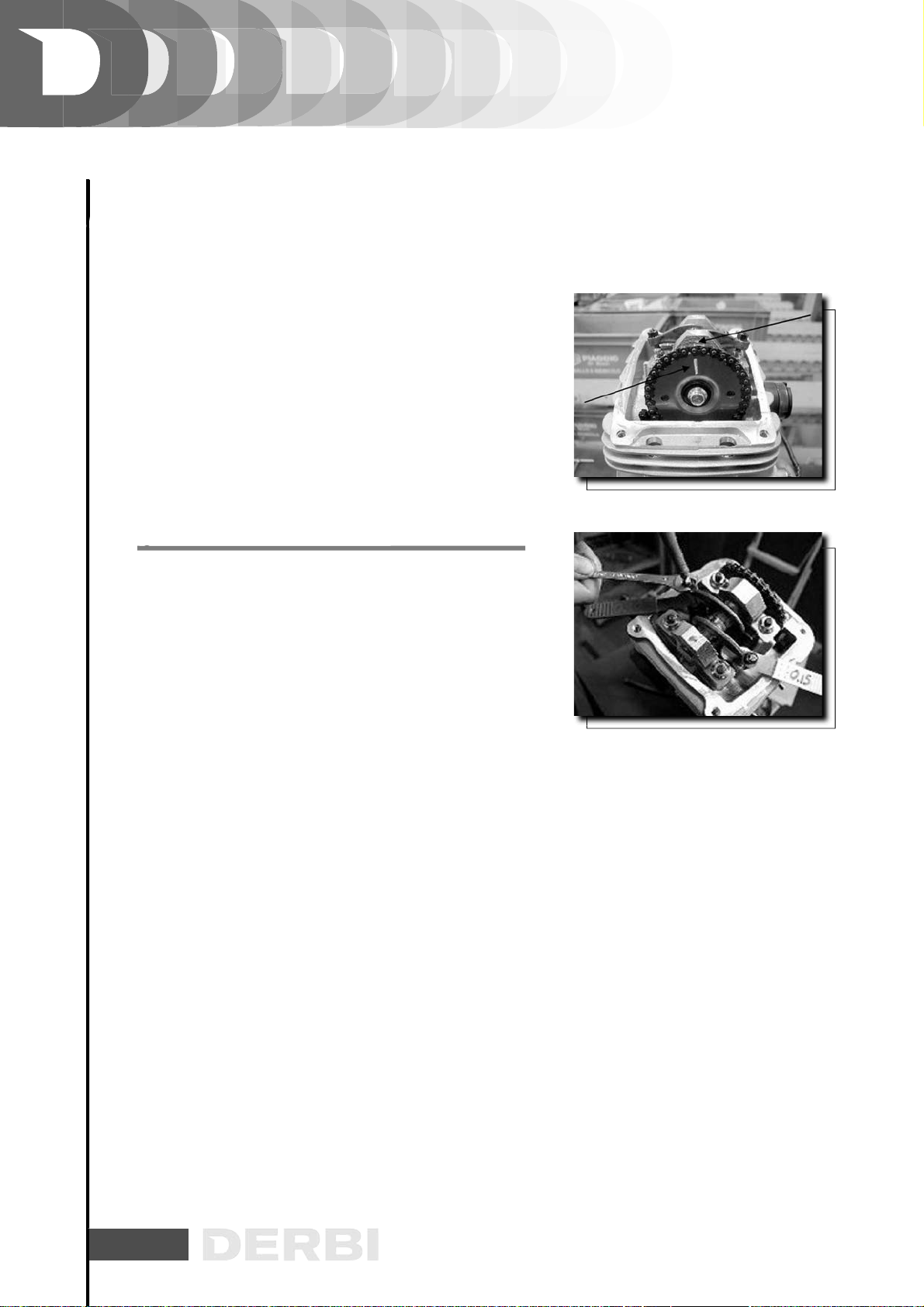
Ensure the reference mark on the camshaft control ring is
aligned with that machined on the head, as shown in the
second figure.
If the marking is on the side opposite to the reference on the
head, perform a complete revolution of the crankshaft, since
the piston must be at the TDC of the ignition phase.
C
HECKING
THE
VALVE
CLEARANCE
In order to carry out the inspection of the valve clearances,
align the reference marks as for the valve timing point,
described earlier.
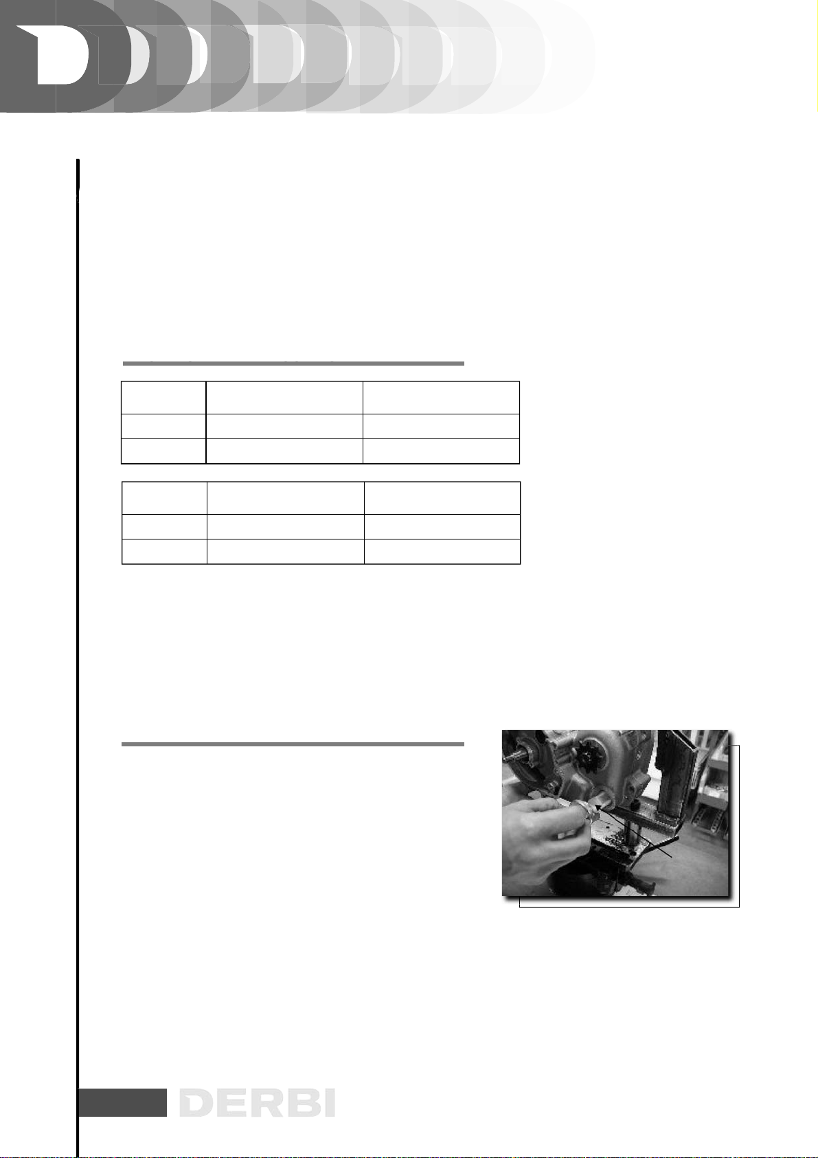
Using a thickness gauge, ensure the clearance between the
valve and the valve adjuster is within the indicated values.
If the valve clearance values differ from those shown below
(for intake and exhaust respectively), proceed with the
adjustment, by loosening the counter nut and then, with the
aid of a screwdriver, loosening or tightening the adjusting
screw as shown in the figure.
CHARACTERISTIC
Valves play:
induction 0,10mm (cold)
Valves play:
exhaust 0,15mm (cold)
Locking torques (N*m)
Rocker-arm adjusting nuts: 7 ÷ 9 Nm
MAINTENANCE
M
M
MAINTENANCE
C

13
C
HE
C
KIN
G
THE
END
CO
MPRE
SS
I
O
N
PRE
SSU
RE
- With the engine cold, remove the spark plug cap.
- Remove the spark plug.
- Using a 10mm adapter, install a compression test manometer on the spark plug housing, and tighten at
the prescribed torque.
- Crank the engine using the starter motor and with the carburettor fully opened, as long as the manometer
reading has stabilized. If the pressure is within the prescribed limits, remove the manometer and refit the
components following the removal procedure in the reverse order.
- If the pressure is below the min allowable pressure, check the engine speed in test conditions. If this is too
low, check the starting system, if this is acceptable, or slightly faster, ensure the proper cylinder base gasket
is installed, and inspect the sealing of the thermal components (piston rings, valves, head, timing system,
etc.).
CHARACTERISTIC
Compression pressure
Min allowable value: 10,5 Kgr
Engine revs:
~ 630 rpm (starting speed).
Locking torques (N*m)
Tightening torque ~10 ÷15 Mm
MAINTENANCE
M
M
MAINTENANCE
CCG CO SS O SSU

14
AUTOMATIC TRANSMISSION
TRAN
S
MI
SS
I
O
N
CO
VER
- Remove the seven cover fixing screws.
- Remove the screw and the kick-start.
- Remove the seeger ring and the washer shown in the figure.
- Remove the sector gear.
KICKSTART
- Search for excessive wear in the toothed segment, the toothed
segment shaft, the gear shaft and its housing in the crankcase,
and the return spring.
- Replace any damaged part.
- Refit the toothed segment as show in the
figure, pre-loading the spring by hand.
REMOVING THE ENGINE PINION
- Using the special tool, retain the engine gear shaft.
- Remove the lock nut and then the gear shaft.
Specific tooling
020288Y Gear shaft retaining tool
- Remove the clutch masses with their gear.
- Remove the two circlips so to free the clutch masses.
- Ensure the teeth are not deformed and/or worn.
ENGINE
E
E
ENGINE
KICKSTART
REMOVING THE ENGINE PINION

15
- Check the thickness of the friction material of the masses.
If the friction material of the mass is found to be missing
the circumferential grooves or cleats, the clutch is to
be considered excessively worn and the masses should
therefore be replaced.
N.B.
WHILE RUNNING-IN, THE MASSES SHOULD SHOW A
CENTRAL CONTACT SURFACE AND MUST DIFFER ONE
FROM THE OTHER. DIFFERENT CONDITIONS MAY CAUSE
A CLUTCH GRABBING PHENOMENON.
CAUTION
DO NOT USE TOOLS TO OPEN THE MASSES, SO TO AVOID
LOAD VARIATIONS IN THE SPRINGS.
INSPECTING THE CLUTCH DRUM
- Check that the clutch bell housing is not worn or
damaged.
- Measure the inside diameter of the clutch bell housing.
N.B.
CHECK THE ECCENTRICITY OF THE CLUTCH DRUM AND
ITS KEYING: MAX 0.15 mm.
CHARACTERISTIC
Standard value:
Ø 92 +0,2 -0 mm
Max allowable value:
Ø 92,3 mm
R
EM
O
VIN
G
THE
C
L
U
T
C
H
- Lock the clutch bell housing with the specific tool.
- Remove the nut, the clutch bell housing and the whole of
the driven pulley assembly.
Specific tooling
020565Y Compass flywheel stop spanner
ENGINE
E
E
ENGINE
INSPECTING THE CLUTCH DRUM

16
REFITTING THE CLUTCH
- Before refitting the assembly, carefully grease the roller
bearing inside the gear housing.
- Refit the clutch assembly, the drum washer, and the nut
using the special tool.
-After refitting, ensure the drum spins freely.
Specific tooling
020565Y Compass flywheel stop spanner
Locking torques (N*m)
Coppia di bloccaggio 40-44 Nm
END GEAR SHAFT
Insert the chain gear shaft and secure with its circlip, as
shown in the figure.
REFITTING THE TRANSMISSION COVER
- Refit the gasket (new).
- Refit the cover tightening the seven screws at the prescribed
torque.
- Refit the oil filler cap.
Locking torques (N*m)
Transmission cover fixing screw: 8 ÷ 10 Nm.
FLYWHEEL COVER
REMOVING THE HUB COVER
Remove the shroud by acting upon the four fittings, as shown
in the figure.
ENGINE
E
E
ENGINE
REFITTING THE CLUTCH
END GEAR SHAFT
REFITTING THE TRANSMISSION COVER
FLYWHEEL COVER

17
REMOVING THE STATOR
- Remove the two stator fixing screws as shown in the figure.
REFITTING THE FLYWHEEL COVER
According to the versions (kick-start/electric). Locking
torques (N*m)
Flywheel cover fixing screw: 2,5 - 3 Nm
F
LYWHEEL
AND
S
TARTIN
G
- Restrain the rotation of the flywheel using the special tool.
- Remove the M10X1.25 flanged nut.
- Extract the flywheel with the specially designed extractor.
Specific tooling
020565Y Compass flywheel stop spanner.
Flywheel tool: 2-claw universal extractor.
Locking torques (N*m)
Flywheel nut 15 Nm
Removing the pick-up:
Remove the two pick-up screws, as shown in the figure.
ENGINE
E
E
ENGINE
REFITTING THE FLYWHEEL COVER
REMOVING THE STATOR
SG

18
REMOVING THE ROCKER
-
ARMS COVER
Remove the four tappet cover fastenings; remove the cover
complete with the 0-ring.
N.B.
IN THE CASE OF LONG MILEAGE OR POOR MAINTENANCE,
CLEAN THE OIL BREATER TUBE.
REMOVING THE TIMING SYSTEM DRIVE
- Remove the chain tensioner central screw, together with its
spring, washer and O-ring.
- Loosen the chain tensioner central screw and remove it
with the spring and the washer.
ENGINE
E
E
- CYLINDER ASSY. AND TIMING SYSTEM
ENGINE - CYLINDER ASSY. AND TIMING SYSTEM
REMOVING THE ROCKER ARMS COVER
REMOVING THE TIMING SYSTEM DRIVE

19
- Remove the tappet cover.
- Remove the central screw and the belleville washer shown
in the figure using the specific tool to lock camshaft ring
gear.
- Remove the camshaft drive pulley and the shim below it.
N.B.
TO FACILITATE THE REMOVAL OF THE CYLINDER HEAD
COMPONENTS, IT IS ADVISABLE TO BRING THE CRANKS-
HAFT TO THE TDC, AT THE END OF THE COMPRESSION
STROKE.
Specific tooling
020565Y Compass flywheel stop spanner
REMOVING THE CAM SHAFT
Remove the bearing check screw shown in the figure.
Remove the camshaft complete with the bearing using the
specific tool shown in the figure.
Eject the bearing from the camshaft using the specific tool
and taking care to fit a screw on the camshaft so as to protect
the camshaft thread.
N.B.
WHENEVER THE BEARING IS SEPARATED FROM THE
CAMSHAFT, REPLACE IT WITH A NEW ONE.
ENGINE
E
E
- CYLINDER ASSY. AND TIMING SYSTEM
ENGINE - CYLINDER ASSY. AND TIMING SYSTEM
REMOVING THE CAM SHAFT

20
Specific tooling
020450Y Camshaft fitting/removing tool
004499Y Bearing extractor
Remove the rocker arm pivot through the hole on the flywhe-
el side and simultaneously remove the rocker arms.
N.B.
MARK THE INSTALLING POSITION OF EACH ROCKER ARM
SO AS TO AVOID FITTING THE INTAKE ROCKER ARM IN
PLACE OF THE EXHAUST ROCKER ARM OR VICE VERSA.
REMOVING THE CYLINDER HEAD
- Remove the timing assembly, the camshaft, and the rocker-
arms.
- Remove the spark plug.
- Remove the two side fastenings shown in the figure.
- Loosen the four cylinder head locknuts in two or three
phases following a crosswise pattern.
- Remove the cylinder head, the two dowel bolts and the
gasket.
N.B.
SHOULD IT BE NECESSARY, THE HEAD MAY BE REMOVED
WITH THE CAM SHAFT AND RACOKERARM PIN. IT SHOULD
BE REMEMBERED, HOWEVER, THAT IT IS THEN NECESSARY
TO HOLD THE CHAIN IN PLACE WITH A METALLIC WIRE AND
CARRY OUT THE CHAIN ADJUSTMENT WHEN REFITTING,
AS DESCRIBED IN THE PARAGRAPH “REFITTING THE TIMING
COMPONENTS”.
- Ensure the chain correctly engages the timing gear-shaft
keyed to the crankshaft, on the flywheel-side.
REMOVING THE CYLINDER HEAD
ENGINE
E
E
- CYLINDER ASSY. AND TIMING SYSTEM
ENGINE - CYLINDER ASSY. AND TIMING SYSTEM
This manual suits for next models
1
Table of contents
Other Derbi Motorcycle manuals

Derbi
Derbi Senda DRD Evo 50 SM User manual

Derbi
Derbi GPR 125 Racing Instruction manual

Derbi
Derbi GP1 50 cc Instruction manual

Derbi
Derbi X-TREME R/SM User manual

Derbi
Derbi SENDA R DRD PRO 50 c.c. User manual

Derbi
Derbi GPR 125 Racing Instruction manual

Derbi
Derbi SENDA 50 DRD RACING X-TREME User manual

Derbi
Derbi GPR 50 2009 User guide

Derbi
Derbi RAMBLA 250 i.e. 2008 User manual

Derbi
Derbi SENDA R/SM 125 4T Baja User manual


