Derbi GPR 125 Racing Instruction manual

WORKSHOP MANUAL
GPR 125 4-stroke

INTRODUCTION ...................................................................
SAFETY REGULATIONS ......................................................
MAINTENANCE REGULATIONS .......................................
SPECIAL TOOLS FOR THE ENGINE ..................................
SPECIAL TOOLS - CHASSIS ..............................................
TECHNICAL DATA ...............................................................
TIGHTENING TORQUES .....................................................
PDI (Pre-delivery inspection) .................................................
LOCATION OF ELEMENTS .................................................
REMOVING BODYWORK ELEMENTS ................................
PERIODICAL MAINTENANCE TABLE .................................
LUBRICATION POINTS .......................................................
INSPECTION AND MAINTENANCE ..................................
INSPECTION AND MAINTENANCE .................................
IDENTIFICATION OF SETS ...................................................
REMOVING THE ENGINE FROM THE FRAME ...................
DISMANTLING THE ENGINE ...............................................
INSPECTING THE ENGINE ELEMENTS ...............................
ASSEMBLING THE ENGINE ..................................................
FITTING THE ENGINE INTO THE FRAME ...........................
DISMANTLING THE CARBURETTOR ...................................
ASSEMBLING THE CARBURETTOR ......................................
CHECKING LEVEL OF THE FLOAT CHAMBER ...................
CHECKING THE VACUM VALVE AND TAPERED NEEDLE
...........
CHECKING THE AUTOMATIC CHOKE ..............................
ENGINE
4
9
10
13
16
17
26
31
34
36
48
51
52
83
85
89
91
104
119
150
155
160
164
164
166
FUEL
SYSTEM
CONTENTS
4
5
MAINTENANCE
3
1
GENERAL
INFORMATION
0
2

COOLING
SYSTEM
CHASSIS
BRAKE SYSTEM
CONTENTS
DIAGRAM OF THE SYSTEM ..................................................
DESCRIPTION OF THE SYSTEM AND CHECKING OF ELEM
....
RENEWING THE WATER PUMP OIL SEAL
..........................
DIAGRAM OF THE SYSTEM ..................................................
DESCRIPCIÓN OF THE LUBRICATION SYSTEM ................
INSPECTING THE WHEELS ...................................................
FRONT WHEEL .......................................................................
FRONT SUSPENSION ...........................................................
STEERING ................................................................................
REAR WHEEL ...........................................................................
REAR SUSPENSION ...............................................................
FRONT BRAKE ........................................................................
REAR BRAKE ............................................................................
GENERAL INDICATIONS ......................................................
LOCATING ELECTRICAL COMPONENTS ..........................
WIRING DIAGRAM ................................................................
CHARGING SYSTEM .............................................................
IGNITION SYSTEM ................................................................
STARTER MOTOR SYSTEM ....................................................
INSTRUMENT PANEL .............................................................
LIGHTING AND INDICATING .............................................
FITTING NEW COMPONENTS ............................................
INSPECTING THE BATTERY AND FUSES ............................
6
7
8
9
10
169
171
175
179
181
185
187
189
195
198
200
203
211
221
223
224
225
226
227
228
235
241
245
LUBRICATING
SYSTEM
ELECTRICAL SYSTEM

4
0
- INTRODUCTION
Particularly important items of information in this manual are distinguished by the following annota-
tions:
Indicates a serious possibility of suffering SEVERE PERSONAL INJURIES OR DEATH if the instructions are
not followed.
Indicates the possibility that the ELEMENT WILL BE DAMAGED if the instructions are not followed.
Presents USEFUL INFORMATION.
This manual has been produced by Nacional Motor, S.A.U. for use by DERBI dealer and sub-agency works-
hops. It is assumed that those using this publication for training purposes and for repairing DERBI machines
have a basic knowledge of mechanics and of the methods inherent in the technique of vehicle repair. Signifi-
cant variations in the characteristics of the machines or in the specific repair operations will be communicated
by means of updates to this manual.
Completely satisfactory work cannot however be carried out without the availability of suitable facilities
and tools, which is why we ask you to consult the pages of this manual referring to special tools and imple-
ments.
NACIONAL MOTOR, S.A.U.
CAUTION
The DERBI logo is the registered trademark and property of DERBI - Nacional Motor, S.A.U.
The total or partial reproduction of any photograph, graphical image or text inserted in this manual is prohibited.
© 2009 DERBI - Nacional Motor, S.A.U.
Created by: www.ciandisseny.com
WARNING
N.B.

5
0
-
I
NTRODUCTION
The aim of this manual is to provide the mechanic with a handy and easy to use reference source. It contains
comprehensive explanations of all the installation, extraction, dismantling, assembly, repair and checking
procedures organized step by step in sequence.
Each chapter is divided into sections whose titles appear at the top of each page.
The titles of the subsections appear in a smaller format than the section titles.
Each operation is accompanied by photographs or illustrations.
Numbering corresponding to the chapter.
1
2
3
4
4
3
1
2

6
0
- INTRODUCTION
LEFT-HAND SIDE (facing forwards)
RIGHT-HAND SIDE (facing forwards)
VIEWS OF THE MACHINE
Whenever Right-hand or Left-hand Side are specified in this manual, it
is understood as meaning facing forward (i.e. in the riding direction).
N.B.
7
0
-
I
NTRODUCTION
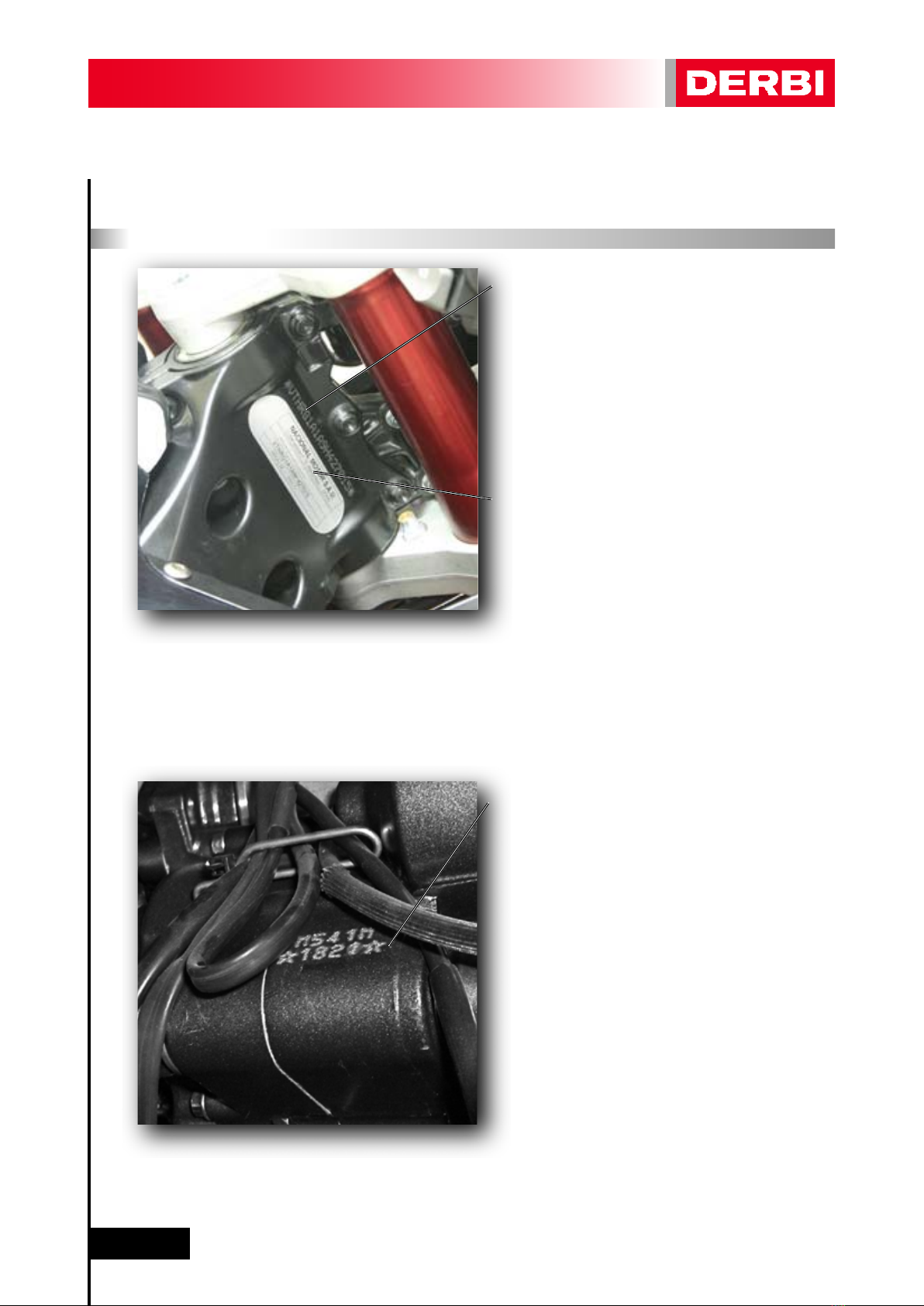
IDENTIFICATION OF THE MACHINE
FRAME SERIAL NUMBER
VTHRG1A1Axxxxxxxx
The frame serial number is located to the right
of the steering column.
MANUFACTURER’S PLATE
The manufacturer’s plate is located to the right
of the steering column.
It includes information about the exhaust
system’s noise emissions (useful in MOT inspec-
tions).
ENGINE SERIAL NUMBER
*xxxx*
The frame serial number is on the rear of
the chassis.

1
-
G
ENERAL INF
O
RMATI
O
N
8
1 - GENERAL INFORMATION
SAFETY REGULATIONS ............................................................
MAINTENANCE REGULATIONS .............................................
SPECIAL TOOLS FOR THE ENGINE .......................................
SPECIAL TOOLS FOR THE CHASSIS .......................................
TECHNICAL DATA ....................................................................
TORQUE TIGHTENING VALUES .............................................
9
10
13
16
17
26
1.1 -
1.2 -
1.3 -
1.4 -
1.5 -
1.6 -

1
-
G
ENERAL INF
O
RMATI
O
N
9
1.1 - SAFETY REGULATIONS
- In the event of having to carry out work on the machine while the engine is running, ensure that the work
area is well ventilated, where possible using suitable extractor fans. Never leave engines running in closed
spaces. The exhaust gases produced contain CO (carbon monoxide) which can cause loss of consciousness
and can lead to death when inhaled.
- The battery electrolyte contains sulphuric acid. Protect eyes, clothing and skin. Sulphuric acid is highly co-
rrosive; in the event of contact with the eyes or skin, wash with copious amounts of water and seek medical
attention immediately. If electrolyte is swallowed accidentally, drink copious amounts of water or milk and seek
medical attention immediately.
- The battery produces hydrogen, a gas that can be highly explosive. Do not smoke, and avoid flames or sparks
close to the battery, especially during battery charging operations.
- Avoid prolonged contact of used engine oil with the skin. Either wear gloves or wash your hands on finishing
handling used oil.
- Petrol is extremely inflammable, and in certain conditions can be explosive. Do not smoke, and avoid sparks
or other points of ignition in the work area.
- Clean brake pads in a well-ventilated place. DO NOT use compressed air to clean brake pads or brake calli-
pers. Although the dust does not contain asbestos, its inhalation can cause respiratory illnesses.
- Brake liquid attacks painted surfaces very aggressively. Protect painted elements with a clean cloth when
performing operations with brake fluid. Wear gloves if possible, since contact of brake fluid with the skin is not
advisable.
- Prevent coolant from spilling onto hot elements, since it produces an “invisible flame” which may lead to a
person receiving burns as a result of not seeing the flame.
- Do not remove the radiator cap when the engine is hot, since the coolant is under pressure and at a high
temperature, and may cause severe burning.
- If coolant enters the eyes, they must be washed immediately with cold water and medical attention sought.
- During normal functioning, the exhaust system and the engine are at a high temperature.
If work has to be carried out on these, either wait until they have cooled down or wear suitable gloves to avoid
being burnt.
WARNING
1
-
G
ENERAL INF
O
RMATI
O
N
10
1.2 - MAINTENANCE REGULATIONS
- Use genuine DERBI spare parts and lubricants recommended by DERBI. Non-genuine or unauthorised parts
may damage the machine.
- Only use the specific tools intended for this machine.
- During re-assembly, always use new oil seals, gaskets, piston rings and grommets.
- After dismantling, clean the components with solvents that are non-inflammable or that have a high flam-
mability point. Grease all working surfaces before assembling, excluding tapered joints.
- After assembly, check that all components have been correctly fitted and that they are functioning perfectly.
- For dismantling, checking and re-assembly operations use only tools with metric measurements. Metric
screws, nuts and bolts are not interchangeable with imperial measurement joining devices. Using unsuitable
tools and joining devices may damage the machine.
- In the case of work on the machine’s electrical circuitry, check that electrical connections have been correc-
tly fitted, especially the earth connections.
Use only genuine DERBI spare parts. For all lubrication tasks use
oils and greases recommended by DERBI. Other makes make
seem similar in their function and appearance, but are inferior
in quality.
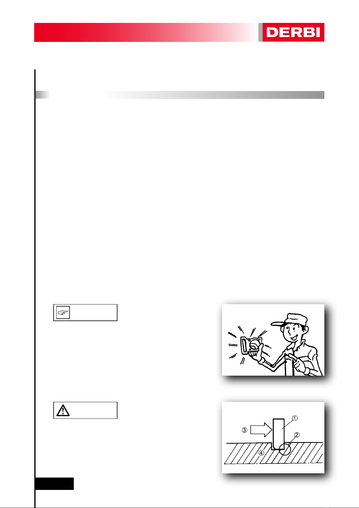
Examine all the locking rings carefully before fitting. Always re-
place the gudgeon pin circlips after every use. Replace distorted
locking rings. On fitting a locking ring (1), ensure that the sharp
edge (2) is on the opposite side to the force (3) to be applied to
it.
See the figure on the side, (4) Axle.
CAUTION
N.B.

1
-
G
ENERAL INF
O
RMATI
O
N
11
Replace all seals, retaining rings and O-rings when servicing the
engine. All surfaces receiving seals, retaining ring edges and O-
rings must be cleaned.
Apply oil to all paired parts and bearing during reassembly.
Apply grease to the retaining ring edges. After removing them,
replace all tab/spacer washers (1) and split pins. Bend the tabs
to fit the flat surfaces of the bolt or nut once they have been
tightened to the specified torque.
WHEN FITTING BEARINGS, EN-
SURE THAT THE SAME PRESSURE
IS APPLIED TO BOTH RACES TO
AVOID DAMAGING THEM.
Fit bearings and retaining rings in such a way that the manufac-
turers marks remain visible. On fitting retaining rings, applying
a thin film of light lithium soap based grease to their edges.
Where appropriate, apply oil generously when fitting bearings.
DO NOT USE COMPRESSED AIR
TO DRY BEARINGS. THIS WILL DA-
MAGE THE BEARING SURFACES.
Remove all the dirt, grime, dust and other foreign material befo-
re removing and dismantling.
N.B.
CAUTION
CAUTION

1
-
G
ENERAL INF
O
RMATI
O
N
12
Use properly cleaned tools and equipment.
See “SPECIAL TOOLS”.
On dismantling parts, always keep paired items together.
This includes gears, cylinders, pistons and other parts submitted
to natural wear in pairs. Paired parts must always be reassem-
bled or replaced together.
While dismantling the motorcycle, clean all the parts and lay
them out on trays in the order dismantled. This speeds up reass-
embly and ensures the correct fitting of all the parts.
KEEP ALL PARTS WELL AWAY FROM
ANY SOURCE OF IGNITION (CIGA-
RETTES, FLAMES, SPARKS, ETC.).
CAUTION
N.B.
WARNING

1
-
G
ENERAL INF
O
RMATI
O
N
13
1.3 - SPECIAL TOOLS FOR THE ENGINE
The following special tools are needed for assembly and for com-
plete and exact adjustments. Only use the proper special tools;
thereby avoiding damage caused by the use of unsuitable tools
or improvised techniques.
Ref. 864486
Camshaft sprocket locking tool.
Ref. 864487
Crankshaft sprocket locking tool.
Ref. 864567
Set of camshaft locking keys.
Ref. 864592
TDC measuring tool (must be accompanied by a dial depth gauge).
This is used to calculate the thickness of the cylinder base gasket
to be used.

1
-
G
ENERAL INF
O
RMATI
O
N
14
Ref. 865207
Set of tools for 125cc 4-stroke 4v engine.
THE SET OF TOOLS FOR THE ENGI-
NE DOES NOT INCLUDE TOOL REF.
866380.
Ref. 865259
Camshaft crown wheel locking tool.
Ref. 865260
Magneto flywheel locking tool.
Ref. 865261
Tool for supporting piston.
N.B.
1
-
G
ENERAL INF
O
RMATI
O
N
15
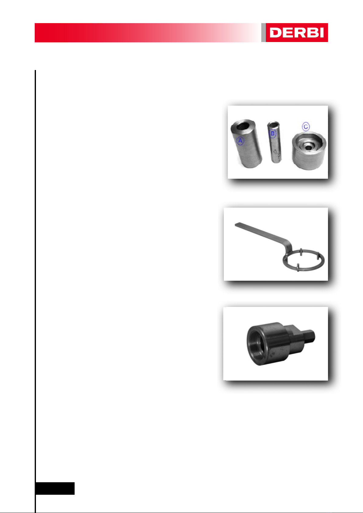
Ref. 866380
Tool kit (A-B-C) for extracting and fitting water pump oil seal.
Ref. 00H05300041
Clutch bell housing locking tool.
Ref. 864868
Magneto flywheel extractor tool.

1
-
G
ENERAL INF
O
RMATI
O
N
16
1.4 - SPECIAL TOOLS - CHASSIS
The following special tools are needed for assembly and for com-
plete and exact adjustments. Only use the proper special tools;
thereby avoiding damage caused by the use of unsuitable tools
or improvised techniques.
Ref. 866714
Tool for adjusting the swinging arm nut.

1
-
G
ENERAL INF
O
RMATI
O
N
17
1.5 - TECHNICAL DATA
GENERAL
MACHINE DIMENSIONS
Distance between wheel shafts
Length
Wide
High
Weight
ENGINE
Diameter x stroke
Cubic capacity
Power
Type
Timing
Compression ratio
Cylinder material
Cylinder head material
Type of lubrication
Cooling
Idling
Gearchange
Final transmission
Polluting emissions reduction system
OTHER PARTS OF THE MOTORCYCLE
Type of chassis
Steering angle
Front suspension
Front suspension travel
Rear suspension
Rear suspension travel
Swinging arm
Front tyre
Rear tyre
Make and model of tyres
Front brake
Rear brake
POWER SUPPLY
Carburettor
TRANSMISSION
Clutch type
Primary transmission ratio
1st gear ratio
2nd gear ratio
3rd gear ratio
4th gear ratio
5th gear ratio
6th gear ratio
Final transmission ratio
Type of chain
1353 mm
1968 mm
720 mm
810 mm
135 Kg
58 mm. x 47 mm
124,2 cm3
15 HP at 9.250 rpm
Single cylinder 4-stroke, 4 valves, Euro 3
Double overhead camshaft (DOHC) chain driven
12:1
Cast iron
Cast aluminium
Semi-wet crankshaft
Liquid
1680 ±50 rpm
Manual, 6 gears
Chain driven
Secondary air system and 2-way catalyser
Double beam of injected aluminium alloy
25º
41 mm Ø inverted hydraulic forks
110 mm
Single shock absorber
135 mm
Double asymmetrical aluminium arm
100/80x17” Tubeless type
130/70X17” Tubeless type
Pirelli Sport Demon
300mm Ø disk
220mmØ disk
Keihin CVK Ø30
Multi-disk in oil bath
(5 driving disks and 4 driven disks).
24/73=1/3,04
11/33=1/3
15/30=1/2
18/27=1/1,5
20/24=1/1,2
25/27=1/1,08
23/22=1,045
14/49=1/3,50
With coupling and 130 links

1
-
G
ENERAL INF
O
RMATI
O
N
18
GENERAL
ELECTRICAL SYSTEM
Spark plug
Gap between electrodes (plug gap)
Charging system
Regulated voltage to battery
Ignition system
Battery
Starting system
CAPACITIES AND TYPES OF FLUIDS
Periodical engine oil change (with oil filter)
Total engine oil (complete dismantling of the engine)
Type of engine oil recommended
Engine oil viscosity
Petrol
Fuel tank capacity
Coolant in radiator
Coolant in expansion chamber (up to max.)
Recommended coolant
Brake fluid
NGK CR8 EB
0,7÷0,8 mm
Three-phase magneto
13v-15v at 8.000 rpm
Electronic CDI type
FTX7L-BS, 12v - 6Ah (MF type)
Electric
1150 ml
1200 ml
AGIP TECH 4T
SAE 10W-40
Lead free 95 octane
14,5 litres
780 ml
230 ml
AGIP PLUS 30%
DOT 4

1
-
G
ENERAL INF
O
RMATI
O
N
19
ENGINE
PISTON DIAMETER (D) CAT M
CAT N
CAT O
CAT P
EXT. DIAMETER MEASUREMENT POINT PISTON (C)
DIAMETER OF PISTON GUDGEON PIN ORIFICE (E)
DIAMETER OF PISTON GUDGEON PIN (a)
Standard
Service limit
PISTON RING TYPE
1st compression ring
Type
Dimension (BxT)
2nd compression ring
Type
Dimension (BxT)
3rd oil scraper ring
Dimension (BxT)
PISTON RING GAP
1st compression ring
2nd compression ring
3rd oil scraper ring
57,953-57,960 mm
57,960-57,967 mm
57,967-57,974 mm
57,974-57,981 mm
7,5 mm
15,003-15,008 mm
14,997-15,00 mm
14,995 mm
Tapered
1 x 2,5 mm
Tapered
1,2 x 2,5 mm
2 x 2,5 mm
0,2-0,35 mm
0,2-0,35 mm
0,2-0,7 mm
C
D
B
T
T
B
B
T
E

1
-
G
ENERAL INF
O
RMATI
O
N
20
ENGINE
CYLINDER DIAMETER CAT M
CAT N
CAT O
CAT P
CYLINDER WARP
CYLINDER-PISTON ASSEMBLY
CYLINDER HEAD WARP SET
ENGINE COMPRESSION VALUE
Standard
Minimum
VALVE ADJUSTMENT VALUE
Inlet (engine cold below 35ºC)
Exhaust (engine cold below 35ºC)
MAXIMUM CAMSHAFT WARP
Inlet
Exhaust
MAXIMUM CAMSHAFT AXIAL PLAY
Inlet
Exhaust
CAM SIZE
Inlet “A”
Inlet “B”
Inlet (lifted) “C”
Exhaust “A”
Exhaust “B”
Exhaust (lifted) “C”
TIMING CHAIN
Type
Timing chain tensioner
58,010-58,017 mm
58,017-58,024 mm
58,024-58,031 mm
58,031-58,038 mm
0,05 mm
0,050-0,064 mm
0,05 mm
more than 15 kg/cm2
13 Kg/cm2
0,012 - 0,015 mm
0,015 - 0,020 mm
0,008 mm
0,008 mm
0,4 mm
0,4 mm
31,44-31,54 mm
23,95-24,05 mm
7,49 mm
30,81-30,91 mm
23,95-24,05 mm
6,86 mm
92RH2005 114 links
Automatic (ratchet)
B
A
C
Other manuals for GPR 125 Racing
1
Table of contents
Other Derbi Motorcycle manuals

Derbi
Derbi GP1 50 cc Instruction manual

Derbi
Derbi Dirtboy 10 Instruction manual

Derbi
Derbi GPR 125 Racing Instruction manual

Derbi
Derbi SENDA R/SM 125 4T Baja User manual

Derbi
Derbi SENDA R DRD PRO 50 c.c. User manual

Derbi
Derbi X-TREME R/SM User manual

Derbi
Derbi Senda DRD Evo 50 SM User manual

Derbi
Derbi RAMBLA 250 i.e. 2008 User manual

Derbi
Derbi SENDA 50 DRD RACING X-TREME User manual

Derbi
Derbi GPR 50 2009 User guide


 2010 Service manual")
