Derbi GP1 125-250 c.c. Instruction manual

GP1125-250 c.c.
WORKSHOP MANUAL

1
DERBI - NACIONAL MOTOR, S.A.U., manufacturer of DERBI motorcycles and mopeds, has produced this
manual with the aim of documenting and simplifying as much as possible the work you need to do to in dis-
mantling and assembling the GP1 125/250 c.c.
The intention is to provide as much assistance as possible to mechanics working for our brand’s dealers and
sub-dealers.
Due to its constant commitment to improving its products, DERBI - NACIONAL MOTOR, S.A.U. Sociedad
Unipersonal reserves the right to introduce any modifications it deems fit, without prior warning.
All the information included in this manual is based on the latest data available at the time of its publication.
The drawings and photographs in this manual are for reference purposes only, and may therefore not be
exactly the same as the corresponding parts of the current model itself.
NACIONAL MOTOR, S.A.U.


3
INTRODUCTION
GENERAL INFORMATION
GENERAL TECHNICAL DATA
RECOMMENDED TOOLS
PERIODIC MAINTENANCE
DISMANTLING
SEAT SIDE TRIM
COWLING
COWLING BOTTOM COVER
WATER-OIL TANK COVER
SIDE COVERS
SHIELD INNER COVER
BATTERY COVER
PETROL TANK COVER
HELMET CARRIER
FOOTRESTS
SIDE COVERS
SHIELD
ENGINE
EXHAUST ASSY - REMOVAL
REMOVAL OF THE WNGINE FROM THE VEHICLE
AUTOMATIC TRANSMISSION
AIR DUCT
REMOVING THE DRIVEN PULLEY SHOFT BEARING
REFFITING THE DRIVEN PULLEY SHOFT BEARING
BAFFLE ROLLER
REMOVING THE DRIVEN PULLEY
INSTEPTING THE CLUTCH DRUM
REMOVING THE CLUTCH
INSPECTING THE CLUTCH
PIN RETAINING COLLAR
REMOVING THE DRIVEN HALF-PULLEY BEARING
INSPECTING THE DRIVEN FIRED HALF-PULLEY
INSPECTING THE DRIVEN SUDING HALF-PULLEY
REFITTING THE DRIVEN HALF-PULLEY BEARING
REFITTING THE DRIVEN PULLEY
INSPECTING THE CLUTCH SPRING
Pág. 1
Pág. 8
Pág. 9
Pág. 30
Pág. 40
Pág. 64
Pág. 64
Pàg. 65
Pág. 65
Pág. 65
Pág. 66
Pág. 66
Pág. 66
Pág. 67
Pág. 68
Pág. 68
Pág. 68
Pág. 69
Pág. 69
Pág. 71
Pág. 71
Pág. 72
Pág. 72
Pág. 73
Pág. 73
Pág. 73
Pág. 74
Pág. 76
Pág. 76
Pág. 77
Pág. 77
Pág. 78
Pág. 78
Pág. 80
Pág. 81

4
REFITTING THE CLUTCH
REFITTING THE DRIVEN PULLEY
DRIVE-VELT
REMOVING THE DRIVING PULLEY
INSPECTING THE ROLLERS CASE
REFTTING THE DRIVING PULLEY
REFITTING THE TRANSMISSION COVER
END GEAR
REMOVING THE WHEEL AXLE
REMOVING THE HUB BEARING
REMOVING THE WHEEL ASXLE BEARING
REMOVING THE DRIVEN PULLEY SHAFT BEARING
INSPECTING THE HUB SHAFT
INSPECTING THE HUB COVER
REFITTING THE WHEEL AXLE BEARING
REFITTING THE HUB COVER BEARING
REFITTING THE HUB BEARING
REFITTING THE HUB COVER
FLYWHEEL COVER
REMOVING THE STATOR
FLYWHEEL AND STARTING
REMOVING FLYWHEEL MAGNETO
INSPECTING THE FLYWHEEL COMPONENTS
REFITTING THE FLYWHEEL MAGNETO
REFITTING THE STATOR MOTOR
CYLINDER ASSY AND TIMING SYSTEM
REMOVING THE ROCKER ARMS COVER
REMOVING THE CAMSHAFT
REMOVING THE CYLINDER HEAD
REMOVING THE VALVES
REMOVING THE CYLINDER - PISTON ASSY
INSPECTING THE SMALL END
INSPECTING THE WRIST PIN
INSPECTING THE PISTON
INSPECTING THE CYLINDER
Pág. 82
Pág. 85
Pàg. 85
Pág. 86
Pág. 87
Pág. 88
Pág. 89
Pág. 90
Pág. 90
Pág. 92
Pág. 92
Pág. 92
Pág. 93
Pág. 93
Pág. 95
Pág. 95
Pág. 95
Pág. 96
Pág. 97
Pág. 97
Pág. 98
Pág. 99
Pág. 101
Pág. 101
Pág. 102
Pág. 103
Pág. 103
Pág. 105
Pág. 105
Pág. 106
Pág. 106
Pág. 107
Pág. 107
Pág. 107
Pág. 110

5
INSPECTING THE PISTON RING
REMOVING THE PISTON RING
CHOOSING THE GASKET
COMPRESSION RATIO VERSION 250
REFITTING THE PISTON RINGS
REFITTING THE CYLINDER
INSPECTING THE CYLINDER HEAD
INSPECTING THE TIMING SYSTEM COMPONENTS
INSPECTING THE VALVE SEALINGS
INSPECTING THE VALVE HOUSINGS
INSPECTING THE VALVES
INSPECTING THE SPRINGS AND HALF-CONES
REFITTING THE VALVES
INSPECTING THE CAMSHAFT
REFITTING THE TIMING SYSTEM COMPONENTS
REFITTING THE ROCKER - ARMS COVER
REFITTING THE INTAKE MANIFOLD
REFITTING THE TIMING SYSTEM COMPONENTS
CRANKCASE - CRANKSHAFT
INSPECTING THE CRANSHFT ALIGNMENT
INSPECTING THE CRANKCASE HALVES
INSPECTING THE CRANKSHAFT PLAIN BEARING
REFITTING THE CRANKCASE HALVES
LUBRICATION
OIL PRESSURE CHACK
OIL PUMP
INSPECTION
REFITTING
REMOVING THE OIL - SUMP
INSPECTING THE BY-PASS VALVE
REFITTING THE OIL SUMP
SAS VALVE
INSPECTING THE CUT-OFF
FUEL SUPPLY
REFITTING THE CARBURETTOR
LEVEL CHECK
INSPECTING THE VALVE AND NEEDLE
INSPECTING THE AUTOMATIC CHOCKE DEVICE
Pág. 111
Pág. 112
Pág. 113
Pág. 115
Pág. 116
Pág. 116
Pág. 117
Pág. 117
Pág. 118
Pág. 118
Pág. 118
Pág. 120
Pág. 120
Pág. 121
Pág. 122
Pág. 128
Pág. 128
Pág. 128
Pág. 129
Pág. 133
Pág. 134
Pág. 135
Pág. 137
Pág. 139
Pág. 140
Pág. 143
Pág. 144
Pág. 145
Pág. 145
Pág. 146
Pág. 146
Pág. 147
Pág. 148
Pág. 149
Pág. 159
Pág. 164
Pág. 166
Pág. 169

6
FORK, SHOCK ABSORBER. ENGINE SUPPORT AND STAND
DISMANTLING FRONT SUSPENSION
INSPECTING THE FRONT FORKS
DISMANTLING
INSPECTION
SWING-ARM
CHECKING THE SWINING ARM
EXHAUST BRACKET
OVERHAUL
REFITTING
CENTRE - STAND
FRONT WHEEL AND BRAKES
REAR WHEEL 125 C.C.
REAR WHEEL 250 C.C.
DISMANTLING
INSPECTING THE FRONT WHEEL
DISMANTLING THE FRONT DISCK CALLIPER
ASSEMBLING THE FRONT WHEEL
REAR WHEEL AND BRAKES
REAR WHEEL 125 C.C.
REAR WHEEL 250 C.C.
DISMANTLING
DISMANTLING THE REAR DISCK CALLIPER
INSPECTING THE REAR WHEEL
RIFTTING THE REAR WHEEL
CIRCUITO DE REFRIGERACIÓN
CIRCUIT DIAGRAM 250 C.C.
CIRCUIT DIAGRAM 150 C.C.
WATER PUMP - OVERHAUL
ELECTRICAL SYSTEM
ELECTRICAL SYSTEM GP1 125-250 C.C.
CHECK CONNECTORS
INSPECTIONS STEPS
DIGITAL INSTRUMENTS UNIT
IGNITION
LIGHTS AND AUTOMATIC CHOKE
RECHARGING THE BATTERY AND STARTTING
Pág. 173
Pág. 175
Pág. 179
Pág. 179
Pág. 180
Pág. 181
Pág. 181
Pág. 182
Pág. 182
Pág. 183
Pág. 184
Pág. 185
Pág. 186
Pág. 186
Pág. 188
Pág. 194
Pág. 196
Pág. 197
Pág. 198
Pág. 198
Pág. 205
Pág. 205
Pág. 206
Pág. 207
Pág. 208
Pág. 218
Pág. 219
Pág. 220
Pág. 220
Pág. 221
Pág. 222
Pág. 223

7
SENSORS AND INDICATORS
TURN INDICATORS AND HORN
IGNITION CIRCUIT
SPARK PLUG
STATOR CHECK
VOLTAGE REGULATOR CHECK
FUSES
DISMANTLING THE BATTERY
BATTERY - INITIAL CHARGE
CAPACITY
INSPECTION THE CHARGING CONDITIONS
RECHARGING
CHARGING SYSTEM
TROUBLESHOOTING
ENGINE
REAR WHEEL TURNS WITH ENGINE TICKING OVER
DIFFICULTY STARTING
EXCESSIVE CONSUMPTION OF OIL/SMOKY EXHAUST
INSUFFICIENT LUBRICATION PRESSURE
THE ENGINE TENDS TO STOP AT MAX GAS OPENING
THE ENGINE TENDS TO STOP AT IDLE
HIGH CONSUMPTION
EXCESSIVELY NOISY WITH EXHAUST
SECONDARY AIR DEVICE ANOMALIES
TRANSMISSION AND BRAKES
INSUFFICIENT BRAKING
BRAKES OVERHEATING
VARIATIONS OR REFRAINED NOISINESS
BATTERY
FLASHING LICHTS NOT WORKING
HEARDENING STERRING
EXCESSIVE STEERING PLAY
NOIZY SUSPENSION
SUSPENSION OIL LEAKAGE
Pág. 224
Pág. 225
Pág. 226
Pág. 226
Pág. 227
Pág. 227
Pág. 230
Pág. 230
Pág. 232
Pág. 232
Pág. 233
Pág. 234
Pág. 235
Pág. 236
Pág. 237
Pág. 237
Pág. 238
Pág. 238
Pág. 239
Pág. 239
Pág. 240
Pág. 240
Pág. 240
Pág. 241
Pág. 241
Pág. 242
Pág. 242
Pág. 242
Pág. 243
Pág. 244
Pág. 244
Pág. 245
Pág. 245

8
REGULATIONS
This section describes the machine’s general safety and maintenance work rules.
SAFETY REGULATIONS
- In the event of having to carry out work on the engine while this is running, ensure that the area is well
ventilated, where possible using extractor fans. Never leave engines running in closed spaces. Exhaust gases
are poisonous.
Petrol is extremely inflammable and in certain conditions may explode. Smoking must not be allowed in the
work area, nor should there be naked flames or sparks.
MAINTENANCE REGULATIONS
- Use genuine DERBI spare parts and lubricants recommended by the manufacturer. Non-genuine or unau-
thorised parts may damage the engine.
Always use new gaskets and oil seals during re-assembly.
After dismantling, clean the components with solvents that are non-inflammable or with a high flammability
point. Lubricate all working surfaces before assembling, excluding tapered joints.
After assembly, check that all components have been correctly fitted and that they are functioning perfectly.
For dismantling, checking and assembly operations, use only tools with metric measurements. Metric screws,
nuts and bolts are not interchangeable with imperial measurement joining devices. Using unsuitable tools
and joining devices may damage the engine.
- In the case of work on the engine involving the electrical circuitry, check that electrical connections have
been correctly fitted.
N.B.
Indicates a note that gives key information to make the procedure easier and clearer.
ATTENTION
Indicates specific procedures that must be carried out to avoid damage to the machine.
WARNING
Indicates specific procedures that must be followed to avoid possible accidents to the person repairing the
machine.
GU O S
S GUOS
MAINTENANCE REGULATIONS

9
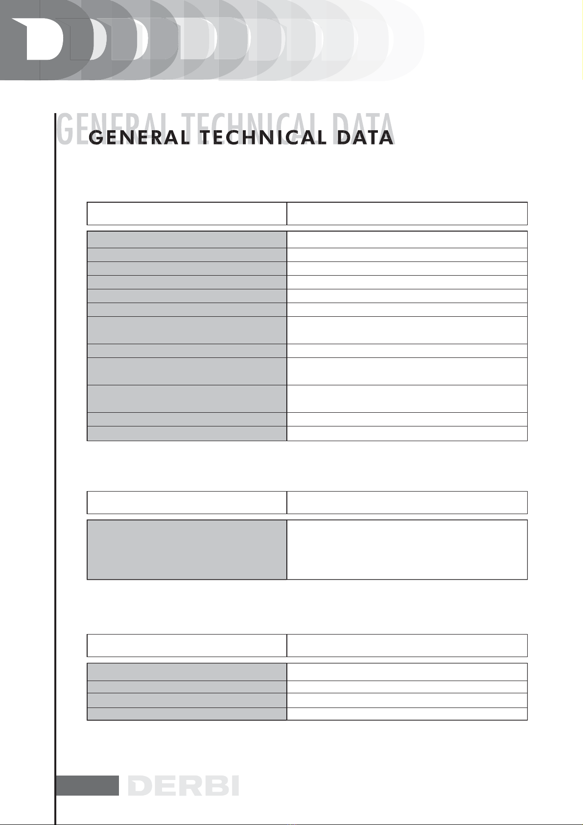
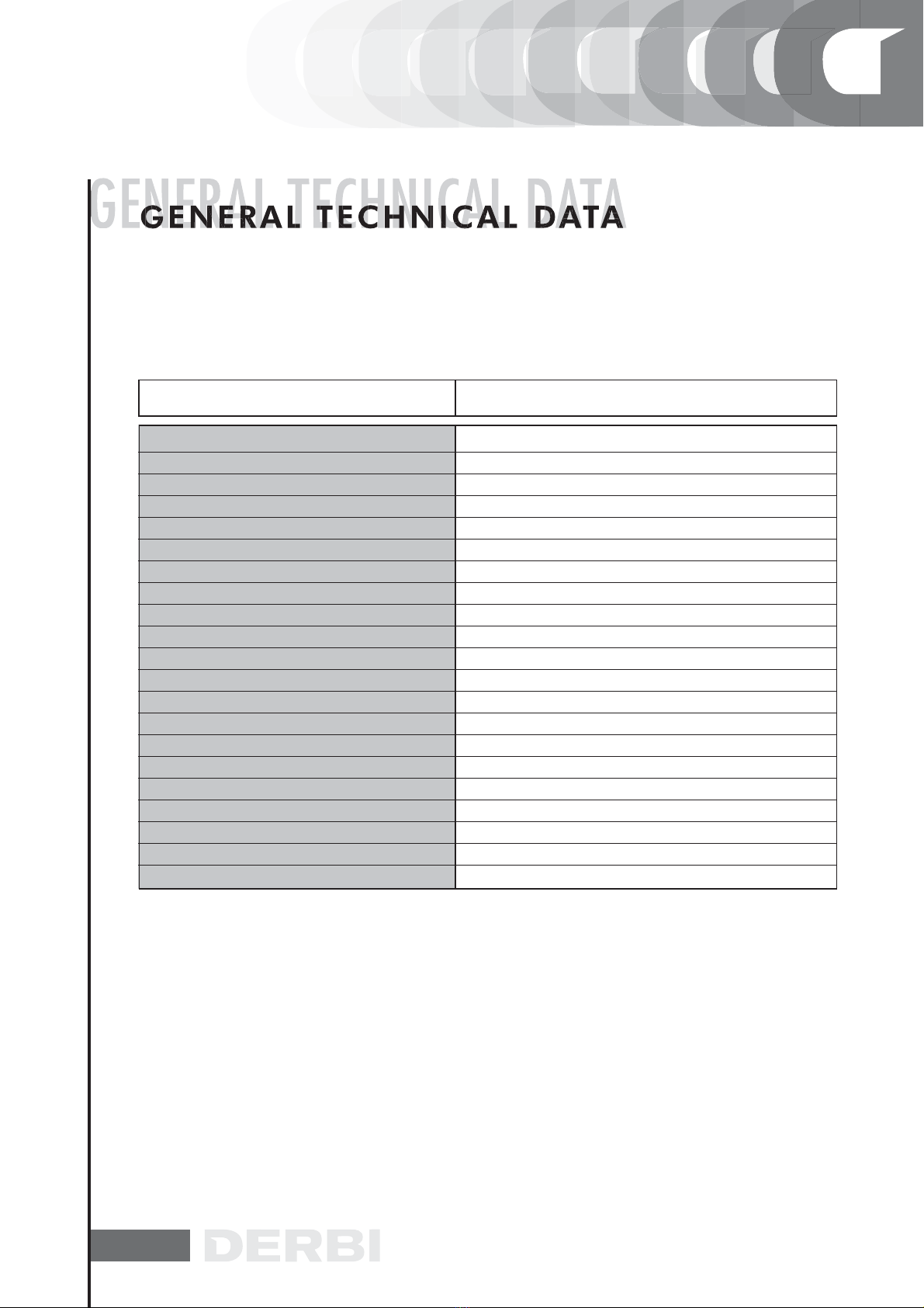
SPECIFICATIONS DESC. / QUANTITY
Maximum length
Maximum height
Length between axles
Handlebar width
Handlebar height
GP1 125 c.c.
GP1 250 c.c.
M434M
M237M
G
P1 12
5
c.c.
G
P1 2
50
c.c.
MACHINE ENGINE PREFIX FRAME PREFIX
VTHPS1A1A
VTHPT1A1A
DIMENSIONS AND WEIGHT
1930 mm.
1225 mm.
1375 mm.
705 mm.
1085 mm.
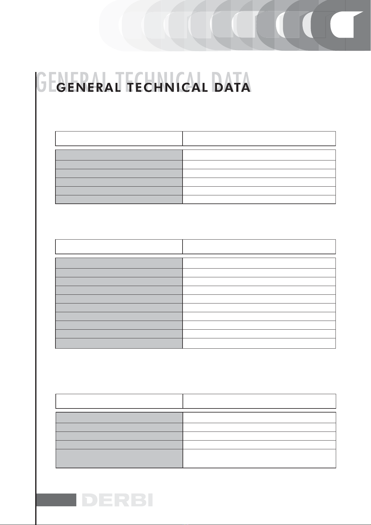
SPECIFICATIONS DESC. / QUANTITY
Engine type
Timing
Int. diameter per stroke (125)
Int. diameter per stroke (250)
Cubic capacity (125)
Cubic capacity (250)
Compression ratio (125)
ENGINE
57x 48,6mm
72 x 60 mm
124,015 cm3
244,290 cm3
12:1
Single cylinder four-stroke and four valve water-cooled
Single overhead cam driven by a chain on the left-hand
side; rockers with three arms and with threaded adjus-
ter.
10
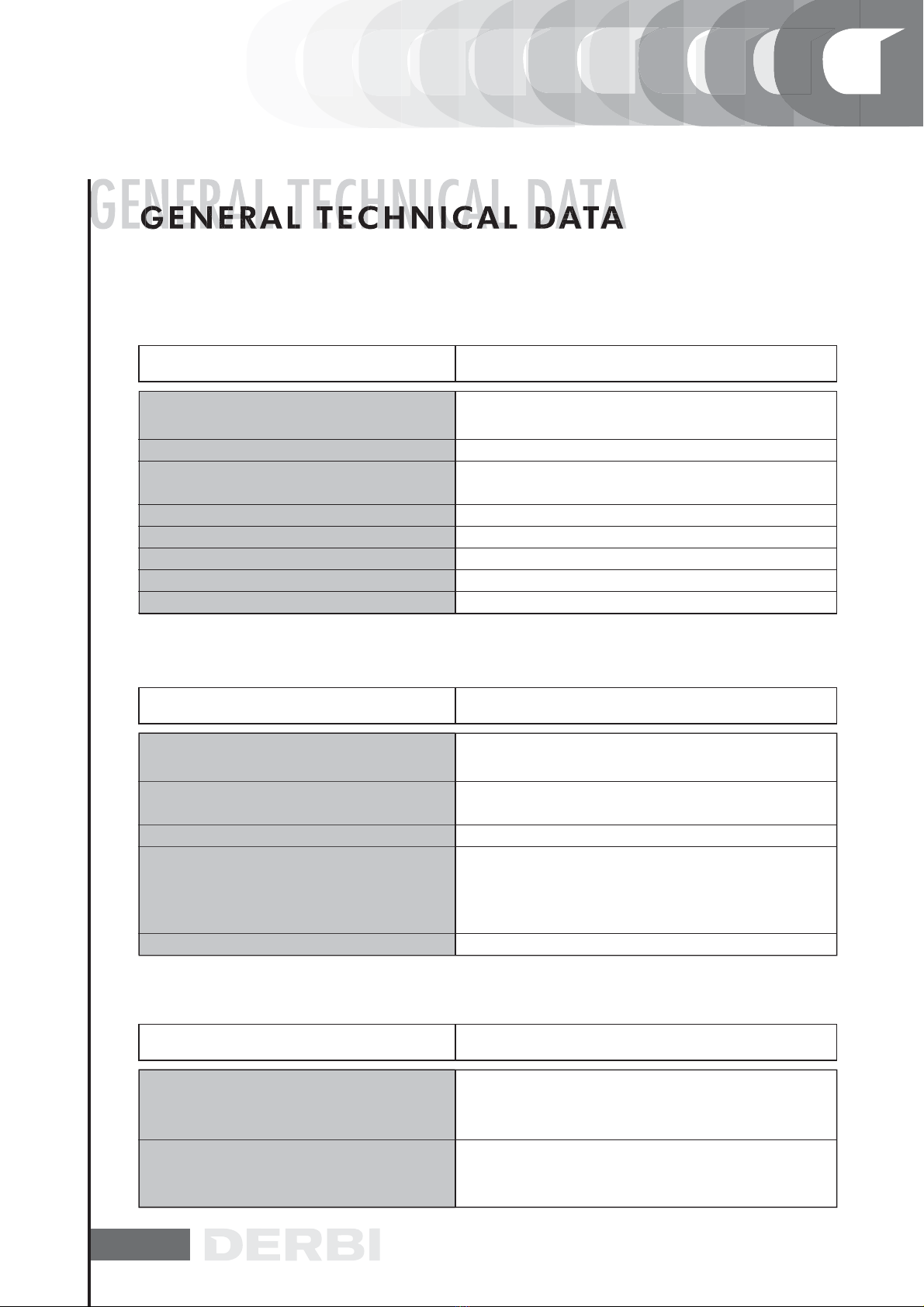
SPECIFICATIONS DESC. / QUANTITY
ENGINE
Engine oil (125)
Engine oil (250)
Fuel tank
Rear hub oil
~ 1100 cc
~ 1200 cc
~ 11 L. with reservation of 2,7 L.)
250 cc
SPECIFICATIONS DESC. / QUANTITY
Transmission
TRANSMISSION
Automatic expandable pulley varistor with servosystem,
trapezoidal belt, self-ventilating dry automatic centrifu-
gal clutch, gear reducer and transmission compartment
with forced air circulation.
SPECIFICATIONS DESC. / QUANTITY
CAPACITIES
10,5-11,5: 1
CVEK-30
WVF 7G* 0 29
WVF-7S*
1650 ±50 r.p.m.
3,8 ± 07
Electric starter motor
11 kw (15CV)at 9700p.r.m.
16,18 Kw (22CV) at 8250 p.r.m.
Sponge-type damped eith a 50% for filters.
Oil - 50% unleaded petrol misture
Engine lubrication with geared twin-screw pump (inside the
oil sump) coomanded by chain and double paper net filter.
With depression pump and petrol through carburettor
Compresion ratio (250)
Keihin Carburettor (125 - 250)
Walbro Carburettor (125)
Walbro Carburettor (250)
Idle speed
Adjustment CO
Air filter
Starter system
Lubrication
Feeding
Max. power (crankshaft) 125cc
Max. power (crankshaft) 250cc
11
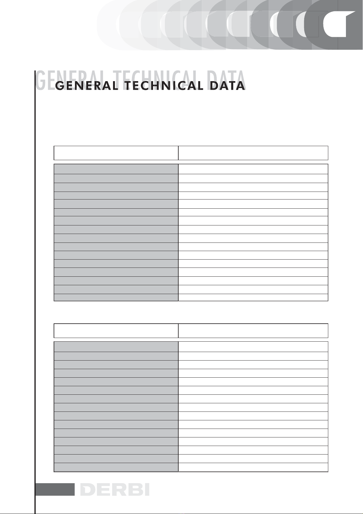
SPECIFICATIONS DESC. / QUANTITY
ELECTRICAL COMPONENTS
10°±1° at 2000 r.p.m. - 34°±1° at 6000 r.p.m.
CHAMPION RG4HC
CHAMPION RG4HC
12V-12Ah
N°1 15A / N°2 15A / N°3 15A
AC current
10° ± 1 at 2000g/min.
28° ± 1 at 6500 g/min.
Electronic with capacitive discharge (CDI) and variable
advance with separate HT coil.
SPECIFICATIONS DESC. / QUANTITY
FRAME AND SUSPENSIONS
100 mm
90/85 mm
Aluminium alloy Delta Box type
Hydraulic telescopic fotk with forward-shifted pin and
Ø 40 mm rods.
Engine functioning as swingarm pivoting on frame
through arm with two degrees of freedom. Pair of
double-acting hydraulic shock absorbers and coaxial
springs with preload adjustment.
SPECIFICATIONS DESC. / QUANTITY
BRAKES
Ø 240 disc with hydraulically operated dual opposed
piston caliper (lever at left end of handlebar).
Ø 245 mm disc with hydraulically operated dual piston
floating caliper (lever at right end of handlebar).
Ignition type
Ignition advance (before T.D.C) 125
Ignition advance
(
before T.D.C
)
Spark plug (125)
Spark plug (250)
Battery
Fuses
Generator
ELECTRICAL SYSTEM
Type
Front suspension
Front wheel max. travel
Rear suspension
Max. rear shock absorber travel
Brakes front
Brakes rear

12
Front wheel rim
Rear wheel rim
Front tyre
Rear tyre
Tyre pressure front wheel (cold)
Tyre pressure rear wheel (cold)
Tyre pressure rear/front wheel (driver and
passenger). (cold)
Aluminium alloy
In light alloy
120 / 70 x 14”
120 / 60 x 14”
1,9 bar
2,0 bar
2,0 / 2.2 bar
SPECIFICATIONS DESC. / QUANTITY
WHEELS AND TYRES
N.B.
CHECK AND ADJUST TYRE PRESSURE WITH TYRES AT AM-
BIENT TEMPERATURE. ADJUST PRESSURE ACCORDING TO
THE WEIGHT OF THE RIDER AND ACCESSORIES.
SECONDARY AIR
The working principie of the SAS for Leader 125 ce engines is
entirely similar to the SAS employed on 2-stroke engines.
The main differences are the following:
Secondary air enters directly into the exhaust duct on the
cylinder head, instead of entering through the exhaust pipe
as in two-stroke engines.
The reed valve found on 2-stroke engines is here replaced by
a membrane. The unit, indicated by an arrow in the figure, is
provided with a cut-off connected to the vacuum inlet on the
intake manifold to shut air intake during deceleraron, so to
prevent detonations in the silencer.
Air is sucked in through hole «A» and flowing through the
first filter is directed towards hole «B».
SECONDARY AIR

13
Flowing through the hole shown in the figure, the air reaches
the second filter, «B», At this point, the tiltered air enters the
membrane device, so to be channelled towards the head.
Flowing through a rigid pipe, flanged to the head, the se-
condary air reaches the exhaust duct thus providing oxygen
addition to the unburnt gases just before they enter the ca-
taiytic converter. The efficiency ofthe catalyzing process is
therefore increased.
El sistema de funcionamiento del SAS para motor Quasar
250 Euro 2 es totalmente similar al funcionamiento del siste-
ma SAS para motor 2T.
Las diferencias son las siguientes:
El aire secundario, en vez de entrar en el silenciador, como
sucede para el 2T entra directamente en el conducto de des-
carga sobre la culata.
14
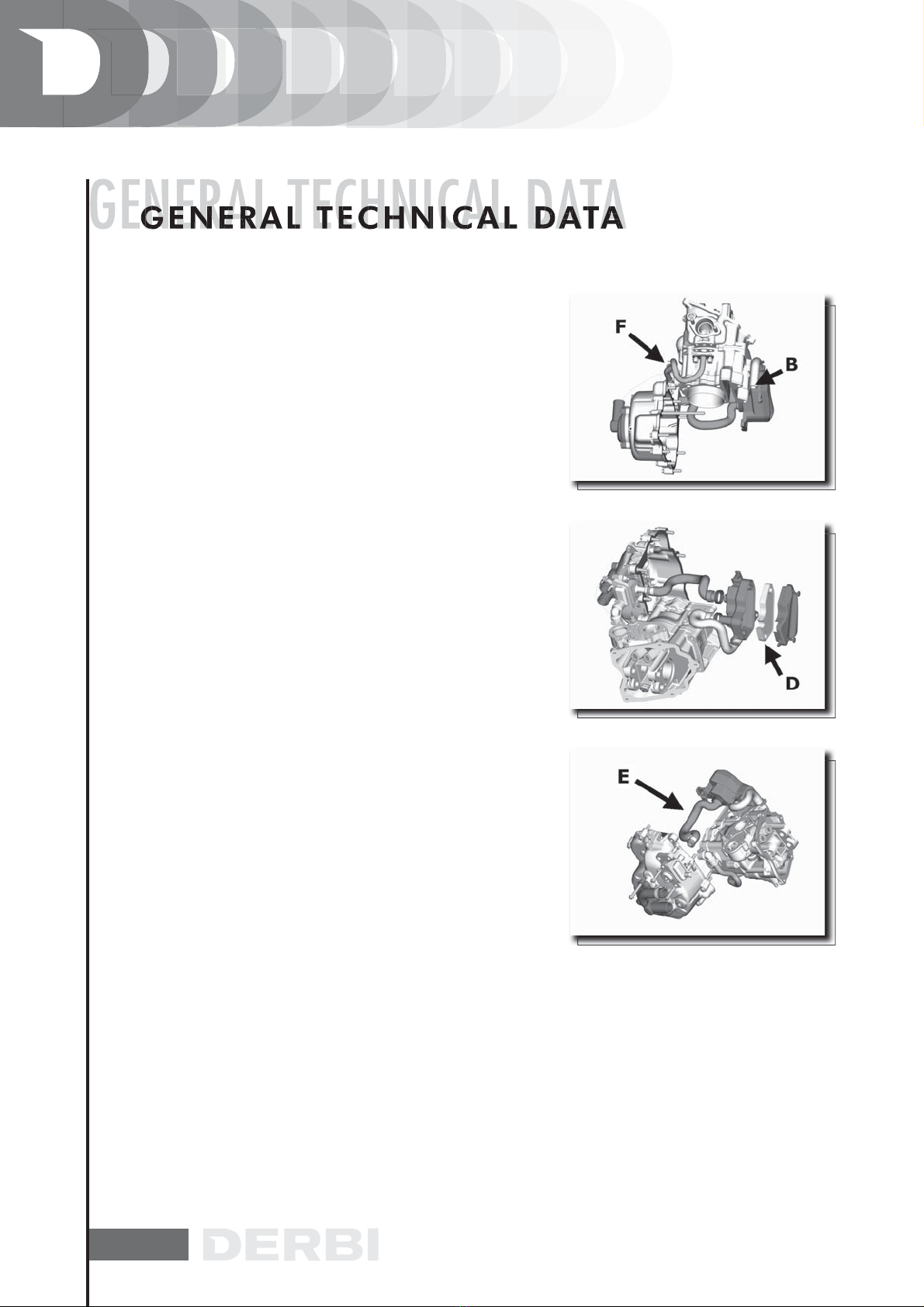
The working principie ofthe SAS for Quasar 250 cc Euro 2
engines is entirely similar to the SAS employed on 2-stroke
engines. The main differences are the following:
Secondary air enters directly into the exhaust duct on the
cylinder head, instead of entering through the exhaust pipe
as in two-stroke engines.
The reed valve found on 2-stroke engines is here replaced
by a membrane.
Unit «A», shown in the figure, is provided with a cut-off con-
nected to the vacuum inlet on the intake manifold to shut air
inlet during deceleration, so to prevent detonations in the
silencer. Air is sucked in through hole «B» and flows inside
the duct into air-box «C» where it is filtered by filtering ele-
ment «D».
The filtered air now enters membrane device «A», through
duct «E» and is then guided towards the head.
Flowing through pipe «F», flanged to the head, secondary
air reaches the exhaust duct thus providing oxygen addition
to the unburnt gases just before they enter the catalytic con
verter.
The efficiency of the catalyzing process is therefore increa-
sed.
15
Depresione type
Printing on the body
Device CUT-OFF
Max. jet
Minimum jet
Max. air jet
Minimum air jet
Idle mixture adjusment screw initial opening
Conical pin
Emulsifier nozzle
Starter air jet
Starter jet
Starter device resistance
Venturi choke
Throttle valve
Choke maximum cone
CVEK30
CVK
Not present
105
35
70
130
2 ±1/4
Ø 2,450
Ø 2,8
Ø 1,5
42
~20
Ø 29
Ø 30,5
Ø 47
SPECIFICATION DESC. / QUANTITY
CARBURATTOR HEIHIN
Version 125
Type to depression
Printing on the body
Device CUT-OFF
Max jet
Minimum jet
Max air jet.
Minimum air jet
Gas valve spring
Idle mixture adjustment screw initial opening
Conical pin printing
Conical pin notches position from top
Emulsifier nozzle
Choke máximum cone
Starter air jet
Starter emulsifier jet
SPECIFICATION DESC. / QUANTITY
CARBURETTOR WALBRO
WVF-7G*
7G
Not present
108
36
115
100
100 gr
2 5/8 ± 1/2
51C
2
Ø 2,7
Ø 1,5
200
130

16
Starter jet
Starter pin diameter
Starter device resistance
Choke
Throttie valve
Choke máximum cone
SPECIFICATION DESC. / QUANTITY
CARBURADOR WALBRO
50
Ø 1,78
~ 40Q
Ø 29 (30,3x27,0)
Ø 33
Ø 48,0
CARBURATTOR HEIHIN
Version 250
Depression type
Printing on the body
CUT-OFF device
Max jet
Minimum jet
Max air jet
Mínimum air jet
Idle mixture adjustment screw initial opening
Conical pin
Emulsifier nozzle
Starter air jet
Starter jet
Starter device resistance
Venturi choke
Throttie valve
Choke máximum cone
SPECIFICATION DESC. / QUANTITY
CVEK30
CVK
Present
100
38
70
115
2½ ± ¼
Ø 2,530
Ø 2,8
Ø 1,5
42
~ 20
Ø 29
Ø 30,5
Ø 47
17
CARBURATTOR WALBRO
Version 250
Depression type
Printing on the body
CUT-OFF device
Max jet
Minimum jet
Max air jet
Mínimum air jet
Gas valve spring
Idle mixture adjustment screw initial opening
Conical pin
Tacche dall’alto spillo cónico
Emulsitier nozzle
Choke máximum cone
Starter air jet
Starter emulsifier jet
Starter jet
Starter pin diameter
Starter device resistance
Choke
Throttie valve
Choke máximum cone
SPECIFICATION DESC. / QUANTITY
WVF-7S*
7S
Presente
118
34
150
31
120 gr
3±½
465
3
Ø 2,7
Ø 1,5
200
130
50
Ø 1,78
~ 40
Ø 29 (30,3x27,0)
Ø 33
Ø 48,0
* The identification letter can vary every time the carburettor is updated.

18
CHASSIS TIGHTENING TORQUES
1,7÷1,9
1,7÷1,9
4,5÷5,5
4,5÷5,5
7÷8
3÷4
3÷4
1,7÷1,9
1,7÷1,9
3÷3,5
6÷6,5
9÷13
0,8÷1
3÷4
1,7÷1,9
1÷1,3
1,7÷1,9
0,8÷1
1,7÷1,9
1,7÷1,9
0,35÷0,45
7÷8
1,5÷1,9
1÷1,2
3,5÷4
2,2÷2,5
11, 5÷12,5
2,7÷2,9
1,7÷1,9
1,7÷1,9
1÷1,2
1,7÷-1,9
0,8÷1
1,7÷2,2
0,4÷0,5
0,35÷0,45
0,8÷1
1,5÷1,9
0,1÷0,2
0,2÷0,35
DESCRIPTION TORQUES
(N.M)
17÷19
17÷19
45÷55
45÷55
70÷80
30÷40
30÷40
17÷-19
17÷19
30÷35
60÷65
90÷130
8 ÷ 10
30÷40
17÷19
10÷13
17÷19
8÷10
17÷19
17÷19
3,5÷4,5
70÷80
15÷19
10÷12
35÷40
22÷25
115÷125
27÷29
17÷19
17÷19
10÷12
17÷19
8÷10
17÷22
4÷5
3,5÷4,5
8÷10
15÷19
1÷2
2÷3,5
TORQUES
(M.KG)
.
.
.
.
.
.
.
SEALER
(•) Sellador the thread type locktite 243
M8X125 8.8 FRONT FRAME-CHASSIS SECUR.DEVICE
M8X125 8.8 SUBCHASSIS-CHASSIS SEC.DEVICE
M10x150 12.9 TOP SHOCK ABSOR.-CHASSIS SEC.DEVICE
M10x150 12.9 BOTTOM SHOCK ABSOR.-ENG. SEC.DEV.
M14x200 8.8 FRONT ENG. SUPPORT-CHASSIS SEC.DEV.
M10X150 8.8 REAR ENG.SUPP-FRONT ENG.SUPP. SEC.DEV.
M10X150 8.8 ENGINE-REAR SUPP. SEC.DEV.
M8X125 8.8 ENGINE SUPP. SILENTBLOC CLAMP SEC.DEV.
M8X125 8.8 SHOCK ABSORBER SUPP. SEC.DEV.
M8X125 12.9 SHOCK ABSOR. SUPP. TO CRANKCASE SEC.DEV.
M12X175 12.9 SHOCK ABSORBER SUPP. TO SUSP. ARM SEC.DEV. M12X175 12.9
M30,5X150 FORKS FLANGE SEC.DEV.
M6x100 HORN-CHASSIS SEC.DEV.
M10X150 8.8 STAND SEC.DEV.
M8Z125 8.8 FOOTREST SUPPORT-CHASSIS SEC.DEV.
M7x100 8.8 EXHAUST PIPE-CYLINDER SEC.DEV.
M8X125 8.8 SILENCER-SUSPENSION ARM SEC.DEV.
M6x100 8.8 STEERING LOCK-CHASSIS SEC.DEV.
M8x125 8.8 HANNDLEBARS-STEERING FORKS SEC. DEV.
M8x125 8.8 HANDLEBAR CLAMP SEC.DEV.
M5x80 8.8 COUNTERWEIGHT-HANDLEBAR SEC.DEV.
M14x150 FRONT WHEEL-FORKS SEC.DEV.
M8x125 FORK ARM LOCK SEC.DEV.
M6x100 10.9 BRAKE DISK-FRONT WHEEL SEC.DEV.
M10x150 8.8 FR. BRAKE CALLIPER-FORKS SEC.DEV.
M8X125 12.9 SUSP. ARM-ENGINE SEC. DEV.
M16X125 10.9 REAR HUB-ENGINE SEC.DEV.
M8X40 10.9 REAR WHEEL-HUB SEC.DEV.
M8X125 8.8 REAR CALLIPER SUPP.-CRANKCASE SEC.DEV.
M8X125 8.8 REAR CALLIPER-CALLIPER SUPP. SEC.DEV.
M6x100 10.9 BRAKE DISK-REAR HUB SEC. DEV.
M8x125 8.8 CLAMP-CHASSIS SEC.DEV.
M6x100 RADIATOR-CHASSIS SEC.DEV.
THERMOSTAT SWITCH-RADIADOR SEC.DEV.
M5X80 8.8 ELECT.FAN-CHASSIS SEC.DEV.
M5x80 VARIOUS METAL PARTS TO CHASSIS SEC.DEV
M6x100 VARIOUS METAL PARTS TO CHASSIS SEC.DEV.
M8x125 VARIOUS METAL PARTS TO CHASSIS SEC.DEV.
M5x80 VARIOUS PLASTIC PARTS TO CHASSIS SEC.DEV.
M6x100 VARIOUS PLASTIC PARTS TO CHASSIS SEC.DEV.
19
Screw clamping manifold to silencer
Screw clamping heat shield to silencer
Exhaust gas intake screw
Screw fixing silencer support arm to crankcase
Exhaust pipe/support bracket fixing screw.
Exhaust pipe/cylinder head fixing nut.
NAME TORQUE IN Nm
EXAUST PIPE
15,5 ÷ 18,5
5 ÷ 6
22 ÷ 26
33 ÷ 41
27 ÷ 30
16 ÷ 18
Hub oilexhaust cap
Oil filter unión on crankcase
Engine oil / net filter drainage cap
Oil filter
Oil pump cover screws
Screws fixing the oil pump to the crankcase
Oil pump control rim screw
Oil pump cover píate screws
Oil sump screws
Minimum oil pressure sensor
NAME TORQUE IN Nm
ENGINE - LUBRICATION
15 ÷ 17
27 ÷ 33
24 ÷ 30
4 ÷ 6
0,7 ÷ 0,9
5 ÷ 6
10 ÷ 14
4 ÷ 6
10 ÷ 14
12 ÷ 14
Spark plug
Cylinder head cover screw (1) (A)
Head fastening side screws
Start up mass screws
NAME TORQUE IN Nm
CYLINDER HEAD
12 ÷ 14
9 ÷ 11 + 180°
11 ÷ 13
7 ÷ 8,5
7 ÷ 8,5
M5 side screw fastening washers on cam
shaft (125 cc)
This manual suits for next models
2
Table of contents
Other Derbi Scooter manuals

Derbi
Derbi BOULEVARD 125 User manual

Derbi
Derbi GP1 OPEN User manual

Derbi
Derbi Variant Sport User manual

Derbi
Derbi GP1 125 E3 User manual

Derbi
Derbi ATLANTIS CITY 50 2T User manual

Derbi
Derbi Rambla 250 User manual

Derbi
Derbi GP1 2004 User manual

Derbi
Derbi Variant Sport User manual

Derbi
Derbi ATLANTIS 50 2004 User manual

Derbi
Derbi boulevard 125 4t Instruction manual


