Derbi BOULEVARD 50 2T Instruction manual

WORKSHOP MANUAL
BOULEVARD 50 2T


INDEX OF TOPICS
CHARACTERISTICS CHAR
TOOLING TOOL
MAINTENANCE MAIN
TROUBLESHOOTING TROUBL
ELECTRICAL SYSTEM ELE SYS
ENGINE FROM VEHICLE ENG VE
ENGINE ENG
SUSPENSIONS SUSP
BRAKING SYSTEM BRAK SYS
CHASSIS CHAS
PRE-DELIVERY PRE DE
TIME TIME

INDEX OF TOPICS
CHARACTERISTICS CHAR

Rules
This section describes general safety rules for any maintenance operations performed on the vehicle.
Safety rules
- If work can only be done on the vehicle with the engine running, make sure that the premises are well-
ventilated, using special extractors if necessary; never let the engine run in an enclosed area. Exhaust
fumes are toxic.
- The battery electrolyte contains sulphuric acid. Protect your eyes, clothes and skin. Sulphuric acid is
highly corrosive; in the event of contact with your eyes or skin, rinse thoroughly with abundant water
and seek immediate medical attention.
- The battery produces hydrogen, a gas that can be highly explosive. Do not smoke and avoid sparks
or flames near the battery, especially when charging it.
- Fuel is highly flammable and it can be explosive given some conditions. Do not smoke in the working
area, and avoid naked flames or sparks.
- Clean the brake pads in a well-ventilated area, directing the jet of compressed air in such a way that
you do not breathe in the dust produced by the wear of the friction material. Even though the latter
contains no asbestos, inhaling dust is harmful.
Maintenance rules
- Use original DERBI spare parts and lubricants recommended by the Manufacturer. Non-original or
non-conforming spare parts may damage the vehicle.
- Use only the appropriate tools designed for this vehicle.
- Always use new gaskets, sealing rings and split pins upon refitting.
- After removal, clean the components using non-flammable or low flash-point solvents. Lubricate all
the work surfaces, except tapered couplings, before refitting these parts.
- After refitting, make sure that all the components have been installed correctly and work properly.
- For removal, overhaul and refit operations use only tools with metric measures. Metric bolts, nuts and
screws are not interchangeable with coupling members with English measurement. Using unsuitable
coupling members and tools may damage the vehicle.
- When carrying out maintenance operations on the vehicle that involve the electrical system, make
sure the electric connections have been done properly, particularly the ground and battery connections.
Characteristics
CHAR - 7

Vehicle identification
VEHICLE IDENTIFICATION
Specification Desc./Quantity
Frame prefix ZAPM44100 ÷ 1001
VTHBR1A1 xxxxxxxxx
Engine prefix
Dimensions and mass
DIMENSIONS AND MASS
Specification Desc./Quantity
Dry weight 97 Kg
Length 1,880
Maximum height 1150 mm
Seat height 785
Width 735
Wheelbase 1,340
Characteristics
CHAR - 8

Engine
ENGINE
Specification Desc./Quantity
Engine type Two-stroke, single cylinder Piaggio Hi-PER2
Bore x stroke 40 X 39.3 mm
Cubic capacity 49.40 cc
Compression ratio 10,3 :1
Carburettor DELL'ORTO PHVA 17.5
CO adjustment 3.5% ± 0.5
Engine idle speed 1800 to 2000 r.p.m.
Air filter Sponge, soaked in a mixture (50% SELENIA Air Filter Oil and
50% unleaded petrol).
Starting system electric starter/kick-starter
Lubrication With blend and variable oil variable according to the engine
revolutions and the throttle valve opening by means of a pump
controlled by the driving shaft with toothed belt.
Fuel supply Gravity feed, with unleaded petrol (with a minimum octane rat-
ing of 95) with carburettor.
Cooling system forced coolant circulation system
Characteristics
CHAR - 9

Transmission
TRANSMISSION
Specification Desc./Quantity
Transmission With automatic expandable pulley variator, torque server, V-
belt, automatic clutch, gear reduction unit.
Capacities
CAPACITIES
Specification Desc./Quantity
Rear hub oil Quantity: approx. 85 cc
oil mixer tank Plastic, capacity ~ 1.2 l
Fuel tank capacity approx. 7.2 litres (of which 1.5 l is reserve)
Electrical system
ELECTRICAL SYSTEM
Specification Desc./Quantity
Type of ignition Capacitive discharge type electronic ignition, with incorporated
high voltage coil
Ignition advance (before TDC) Fixed 17° ± 1
Recommended spark plug CHAMPION RN2C
Battery 12V-4Ah
Main fuse 7.5 A
Generator In alternate current with three output sections
Frame and suspensions
FRAME AND SUSPENSIONS
Specification Desc./Quantity
Type of chassis Welded tubular steel chassis with stamped sheet reinforce-
ments.
Front suspension Telescopic mechanical fork, 76mm travel.
Rear suspension Single hydraulic shock absorber, 72.5-mm travel
Brakes
FRENI
Specification Desc./Quantity
Front brake Disc brake (Ø 200 mm) with hydraulic control (lever on the right
end of the handlebar) and floating calliper.
Rear brake drum brake (Ø 140 mm) with mechanical linkage.(l.h. brake
lever).
Wheels and tyres
WHEELS AND TYRES
Specification Desc./Quantity
Front wheel rim Die-cast aluminium alloy 3.50 x 12"
Front tyre Tubeless, 120/70-12"
Characteristics
CHAR - 10

Specification Desc./Quantity
Rear wheel rim Die-cast aluminium alloy: 3.00"x12"
Rear tyre Tubeless, 120/70 - 12"
Front tyre pressure 1.8 bar
Rear tyre pressure 2 bar
Rear wheel pressure (rider and passenger): 2.3 bar
Secondary air
Follow these steps to clean the sponge filters of
the secondary air system:
1) Remove the snap-on plastic cover (1) on the
transmission cover using a small screwdriver as a
lever on the retaining tongues in order to insert one
of the three slots found on that cap.
2) Wash the polyurethane sponge with water and
soap, dry all components with compressed air and
refit to place. Refit the intake cap respecting the
angle reference.
3) Undo the two fixing screws (2) on the aluminium
cover of the secondary air housing in order to
reach the polyurethane sponge inside that hous-
ing; clean as indicated in point 2) and refit all
elements after checking the steel tab is not de-
formed and/or does not guarantee correct tight-
ness at its fitting; replace if necessary.
N.B.
UPON REFITTING, MAKE SURE TO CORRECTLY FIT THE
TAB IN ITS FITTING ON THE TWO PLASTIC AND ALUMI-
NIUM COVERS.
CAUTION
WHILE CARRYING OUT OPERATION 3), ALWAYS CHECK
THE TWO RUBBER COUPLINGS (3) ON ONE END OF THE
SECONDARY AIR PIPE FOR CORRECT TIGHTNESS AND
CONTINUITY; IF NECESSARY, REPLACE THEM AND USE
NEW CLAMPS TO FIX THEM.
Carburettor
50cc Version
Characteristics
CHAR - 11

Dell'Orto
DELLORTO CARBURETTOR
Specification Desc./Quantity
Type PHVA 17.5 RD
Diffuser diameter Ø 17.5
Regulation reference number 8423
Maximum nozzle: 53
Maximum air nozzle (on the body): Ø 1.5
Tapered pin stamped code: A22
Pin position (notches from above): 1
Diffuser: 209 HA
Minimum nozzle: 32
Minimum air nozzle (on the body): Free
Initial minimum mix screw opening: 1 1/2
Starter jet 50
Starter air nozzle (on the body): Ø 1.5
Stroke of starter pin: 11 mm
Gasoline inlet hole Ø 1.5
Tightening Torques
FRONT BRAKE
Name Torque in Nm
Brake fluid pump - hose fitting 16 ÷20 Nm
Brake fluid pipe-calliper fitting 19 ÷ 24
Calliper tightening screw 24 ÷ 27
Disc tightening screw 8 ÷ 10
Oil bleed screw 7 ÷ 10
FRONT SUSPENSION
Name Torque in Nm
Lower fork fixing screw 15 ÷ 20
Front wheel axle nut 45 - 50
STEERING ASSEMBLY
Name Torque in Nm
Upper steering ring nut 35 ÷ 40
Steering lower ring nut 8 ÷ 10
Handlebar fixing screw 50 ÷ 55
ENGINE ASSEMBLY
Name Torque in Nm
Clutch bell nut (**) 40 ÷ 44
Clutch lock ring nut 55 ÷ 60
Nut locking driving pulley on crankshaft (**) 40 ÷ 44 Nm
Start-up lever screw 12 ÷ 13
Flywheel nut (**) 40 ÷ 44
Flywheel fan screws 3 ÷ 4
Half-crank case joint bolts 12 ÷ 13
Bolts holding exhaust pipe to the crankcase 22 ÷ 24
Screws holding the filter box to the crank case 4 ÷ 5
Head nuts 10 ÷ 11
Starter screws 12 ÷ 13
Ignition spark plug 25 ÷ 30
Hub oil drainage cap 3 ÷ 5
Oil hub level dipstick Manual
Rear hub cap screws 12 ÷ 13
Transmission cover screws 12 ÷ 13
Inlet manifold screws 8 ÷ 9
Characteristics
CHAR - 12

Name Torque in Nm
Flywheel hood fixing screws 1 ÷ 2
Cylinder hood fixing screws 3.5 ÷ 5
Stator clamping screws 3 ÷ 4
Pick-Up clamping screw 4 ÷ 5
Mixer clamping screws 3 ÷ 4
Screw fixing brake lever to the journal on the engine 12 ÷ 13
CHASSIS
Name Torque in Nm
Swinging arm - engine pin* 33 ÷ 41
Frame/swing-arm bolt (*) 64÷72
Shock absorber - chassis nut (*) 20 to 25 Nm
shock absorber - engine pin (*) 33 to 41 N·m
Rear wheel axle (*) 104÷126 N·m
Centre-stand mounting bracket bolt 25÷30 N·m
Centre-stand mounting bracket screw 20÷25 N·m
Side stand fixing screw 12 ÷ 20
Side stand bracket fixing screw 15 ÷ 20
Overhaul data
Assembly clearances
Cylinder - piston assy.
COUPLING BETWEEN PISTON AND CYLINDER
Name Initials Cylinder Piston Play on fitting
Standard coupling M 40.005 - 40.012 39.943 - 39.95 0.055 - 0.069
Standard coupling N 40.012 - 40.019 39.95 - 39.957 0.055 - 0.069
Standard coupling O 40.019 - 40.026 39.957 - 39.964 0.055 - 0.069
Standard coupling P 40.026 - 40.033 39.964 - 39.971 0.055 - 0.069
coupling 1st oversize M1 40.205 - 40.212 40.143 - 40.15 0.055 - 0.069
coupling 1st oversize N1 40.212 - 40.219 40.15 - 40.157 0.055 - 0.069
coupling 1st oversize O1 40.219 - 40.226 40.157 - 40.164 0.055 - 0.069
coupling 1st oversize P1 40.226 - 40.233 40.164 - 40.171 0.055 - 0.069
Coupling 2nd oversize M2 40.405 - 40.412 40.343 - 40.35 0.055 - 0.069
Coupling 2nd oversize N2 40.412 - 40.419 40.35 - 40.357 0.055 - 0.069
Coupling 2nd oversize O2 40.419 - 40.426 40.357 - 40.364 0.055 - 0.069
Coupling 2nd oversize P2 40.426 - 40.433 40.364 - 40.371 0.055 - 0.069
Characteristics
CHAR - 13
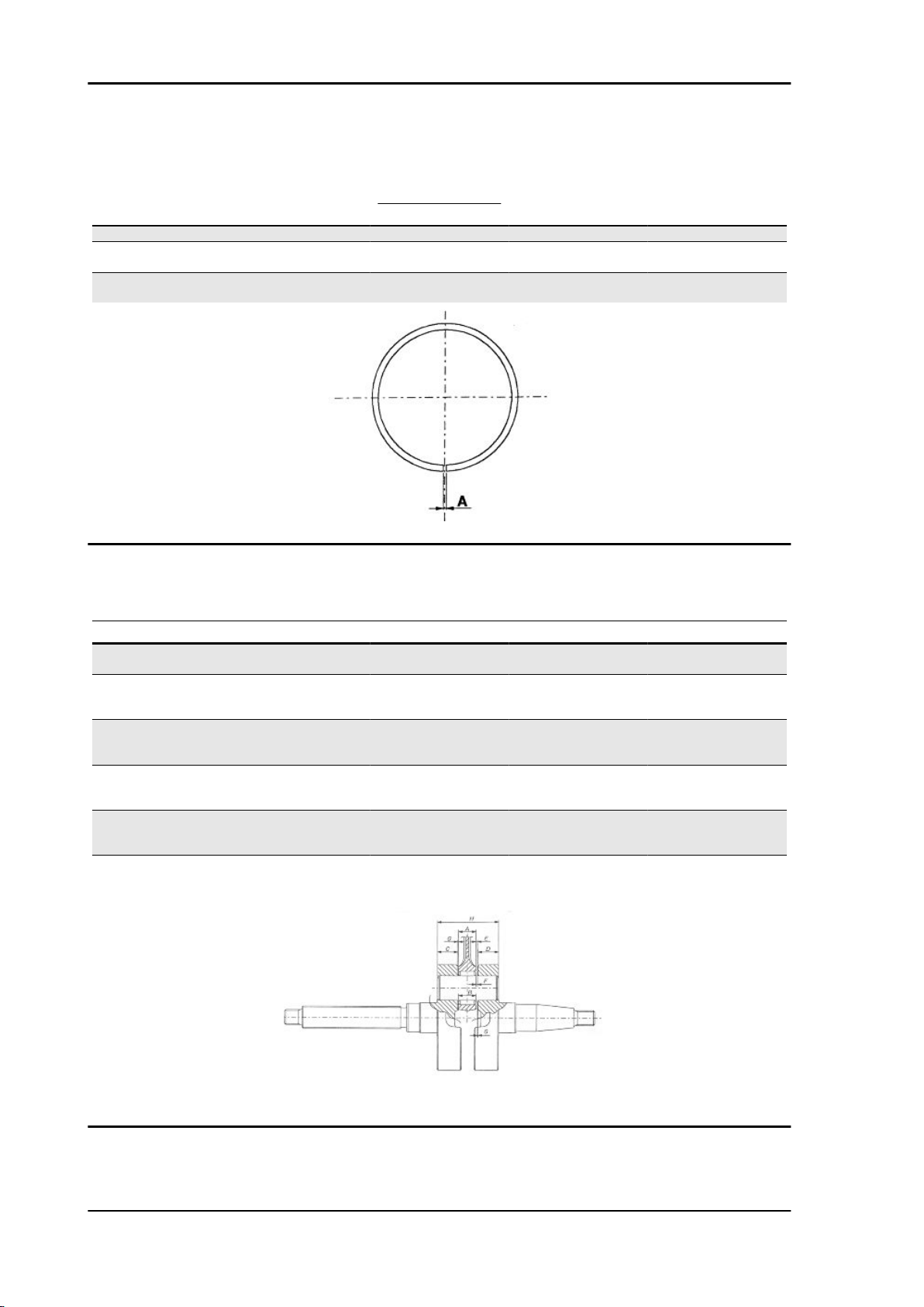
Piston rings
SEALING RING
Name Description Dimensions Initials Quantity
Compression ring 40 A 0.10 to 0.25
Compression ring 1st
oversize
40.2 A 0.10 to 0.25
Compression ring 2nd
Oversize
40.4 A 0.10 to 0.25
Crankcase - crankshaft - connecting rod
AXIAL CLEARANCE BETWEEN CRANKCASE, CRANKSHAFT AND CONNECTING ROD
Name Description Dimensions Initials Quantity
Connecting rod 11.750-0.05 A clearance E = 0.25 to
0.50
shoulder washer 0.5 ± 0.03 G clearance E = 0.25 to
0.50 - clearance F =
0.20 to 0.75
Half-shaft, transmission
side
13.75+0.040 C clearance E = 0.25 to
0.50 - clearance F =
0.20 to 0.75
Flywheel-side half-shaft 13.75+0.040 D clearance E = 0.25 to
0.50 - clearance F =
0.20 to 0.75
Lining between the
shoulders
40.64 H clearance E = 0.25 to
0.50 - clearance F =
0.20 to 0.75
Cage 11.800-0.35 B clearance F = 0.20 to
0.75
Slot packing system
This type of engines foresees the use of one size of basic gaskets.
Characteristics
CHAR - 14

For 25 km/h engine type versions, use 2 gaskets between cylinder and crankcase.
Products
RECOMMENDED PRODUCTS TABLE
Product Description Specifications
AGIP ROTRA 80W-90 Rear hub oil SAE 80W/90 Oil that exceeds the re-
quirements of API GL3 specifications
AGIP CITY HI TEC 4T Oil to lubricate flexible transmissions
(brake, throttle control and mixer, odom-
eter)
Oil for 2-stroke engines: SAE 5W-40, API
SL, ACEA A3, JASO MA
AGIP FILTER OIL Oil for air filter sponge Mineral oil with specific additives for in-
creased adhesiveness
AGIP CITY TEC 2T Mixer oil synthetic oil for 2-stroke engines: JASO
FC, ISO-L-EGD
AGIP BRAKE 4 Brake fluid FMVSS DOT 4 Synthetic fluid
MONTBLANC MOLYBDENUM
GREASE
Grease for driven pulley shaft adjusting
ring and movable driven pulley housing
Grease with Molybdenum disulphide
AGIP GREASE PV2 Grease for steering bearings, pin seats
and swinging arm
White anhydrous-calcium based grease
to protect roller bearings; temperature
range between -20 C and +120 C; with
NLGI 2; ISO-L-XBCIB2.
AGIP GREASE SM 2 Grease for odometer transmission gear
case
Lithium grease with NLGI 2 molybdenum
disulphide; ISO-L-XBCHB2, DIN
KF2K-20
AGIP GP 330 Grease for brake control levers, throttle,
stand
White calcium complex soap-based
spray grease with NLGI 2; ISO-L-XBCIB2
Characteristics
CHAR - 15

INDEX OF TOPICS
TOOLING TOOL

TOOLS
Stores code Description
001330Y Tool for fitting steering seats
001467Y006 Pliers to extract 20 mm bearings
001467Y007 Driver for OD 54 mm bearing
001467Y009 Driver for OD 42-mm bearings
001467Y013 Pliers to extract ø 15-mm bearings
001467Y014 Pliers to extract ø 15-mm bearings
Tooling
TOOL - 17

Stores code Description
001467Y017 Bell for bearings, OD 39 mm
001467Y021 Extraction pliers for ø 11 mm bearings
002465Y Pliers for circlips
006029Y Punch for fitting fifth wheel seat on steer-
ing tube
020004Y Punch for removing fifth wheels from
headstock
020055Y Wrench for steering tube ring nut
020150Y Air heater mounting
Tooling
TOOL - 18

Stores code Description
020151Y Air heater
020162Y Flywheel extractor
020163Y Crankcase splitting plate
020164Y Driven pulley assembly sheath
020165Y Start-up crown lock
020166Y Pin lock fitting tool
Tooling
TOOL - 19

Stores code Description
020261Y Starter spring fitting
020262Y Crankcase splitting plate
020265Y Bearing fitting base
020325Y Pliers for brake-shoe springs
020329Y Mity-Vac vacuum-operated pump
020330Y Stroboscopic light to check timing
Tooling
TOOL - 20
Other Derbi Scooter manuals

Derbi
Derbi GP1 2004 User manual

Derbi
Derbi BOULEVARD 125 User manual

Derbi
Derbi Variant Sport User manual

Derbi
Derbi GP1 OPEN User manual

Derbi
Derbi GP1 125 E3 User manual

Derbi
Derbi boulevard 125 4t Instruction manual

Derbi
Derbi Variant Sport User manual

Derbi
Derbi GP1 125-250 c.c. Instruction manual

Derbi
Derbi Rambla 250 User manual

Derbi
Derbi ATLANTIS 50 2004 User manual


