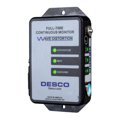
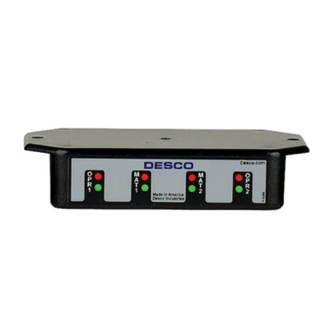
Desco EMIT 50513 Installation guide

TB-6511 01/04 Page 1 of 4
Single Wire Multifunction Wrist Strap
Monitor Operation and Maintenance
Figure 1. Item 50513 Single Wire Multifunction Wrist Strap
Monitor
Description
The Desco EMIT 50513 contains all the monitoring
functions required to ensure that the wrist straps,
worksurface, and ground connections of a workstation are
fully functional at all times.
The 50513 continuously monitors:
1. The operator wrist strap for changes in load, or open
circuit
2. The worksurface for resistance
3. Electrical ground (or earth ground) for continuity and low
resistance
Installation
Fasten the 50513 with the supplied hook-and-loop self
adhesive strip. The 50513 requires only 4 connections to
work properly: 1) electrical ground, 2) worksurface, 3) single
wire wrist strap, and 4) electrical power.
GROUND
The electrical ground connection is made through the cord
of the three-wire US/CSA approved AC adapter. Per the
ESD Association ANSI/ESD S20.20, electrical ground is
preferred.
If you are using earth ground, make the connection by
attaching a wire to a water pipe clamp or use an 8" to 12"
copper ground stake. A large number of workstations can
be connected to a single heavy gauge ground wire. Attach
the ground wire to the pin jack adapter on the back of the
unit labeled “GND”. Solder the wire directly to the banana
plug-to-pin jack adapter or use a banana plug on the
ground wire. This pin jack is internally connected to the
banana jack on the front of the unit marked “WRIST
STRAP/GUEST”. This jack may be used as an auxiliary
electrical ground connection point for another piece of
equipment, or as a plug-in point for a wrist strap by persons
visiting the workstation.
Make the worksurface monitoring connection by attaching
two wires to the worksurface. Use “snap” connectors or a
CK-1 contact kit with the two contact points positioned
approximately 1" or less apart. Attach one wire to the pin
jack adapter on the back of the unit labeled “BENCH” and
the other wire to system ground.
Complete the installation by plugging the UL/CSA approved
AC adapter DIN plug into the DIN jack on the rear panel
marked “POWER”, and the adapter into a grounded outlet.
Proper installation is indicated by a red “STRAP” LED, a
green “BENCH” LED, a green “GND” LED, and an
approximately 3 second activation on the audible alarm.
(NOTE: All three LEDs must be green in order to reset
the audible alarm circuit after an alarm condition.)
Wear the single wire wrist strap and plug the cord into the
front panel “WRIST STRAP MONITOR” jack. Observe that
all three green LEDs are on.
Operation
Ground Monitor:
The green “GND” indicator will illuminate when the total
resistance to ground measures less than 100 ohms. Ground
loop resistance greater than 100 ohms will produce a red
“GND” indicator and an audible alarm for approximately 3
seconds.
Check for proper operation by disconnecting the ground
wire from the “GND” terminal or by floating the ground pin
on the power adapter by way of a two-prong to three-prong
adapter (readily available in hardware stores). The “GND”
indicator should illuminate red and the alarm should sound
for approximately 3 seconds when either ground is
interrupted.
DESCO EMIT WEST - 3651 Walnut Avenue, Chino, CA 91710 • (909) 627-8178 • Fax (909) 627-7449
DESCO EMIT EAST - 90 Hudson Road, Canton, MA 02021-1407 • (781) 821-8370 • Fax (781) 575-0172 • Web Site: http://www.descoemit.com
Made in America
TECHNICAL BULLETIN TB-6511
© 2004 DESCO INDUSTRIES INC.
Employee Owned

TB-6511 Page 2 of 4
DESCO EMIT WEST - 3651 Walnut Avenue, Chino, CA 91710 • (909) 627-8178 • Fax (909) 627-7449
DESCO EMIT EAST - 90 Hudson Road, Canton, MA 02021-1407 • (781) 821-8370 • Fax (781) 575-0172 • Web Site: http://www.descoemit.com
Wrist Strap Test:
When power is supplied to the 50513, the “STRAP”
indicator will illuminate red until a functional single wire wrist
strap is worn and plugged into the “WRIST STRAP
MONITOR” jack. Plug a single wire wrist strap into the
connector marked “WRIST STRAP OPERATOR” place the
strap securely around either wrist. the “STRAP” indication
will be green if the total capacitance of operator and wrist
strap is above approximately 50 picofarads and the series
resistance of the wrist strap cord is less than approximately
2 megohms. Should the capacitance or resistance change
above or below these thresholds, the “STRAP” indication
will illuminate red and the alarm will sound for
approximately 3 seconds.
A wrist strap, plugged into the “WRIST STRAP/GUEST”
banana jack, is connected directly to earth ground and is
not continuously monitored.
Because of the inherent nature of single-wire wrist strap
monitoring based on the body capacitance principle, it may
sometimes be necessary to adjust an individual unit to a
particular operator’s body capacitance. Adjust the unit by
removing the top cover of the unit and turning calibration
potentiometer R7 until the “STRAP” indicator just turns red
while the operator is wearing the wrist strap. Then, slowly
turn the potentiometer in the opposite direction until the
“STRAP” indicator just returns to green. Verify that
removing the wrist strap will cause the indicator to turn red
and that the alarm sounds for approximately 3 seconds.
Worksurface Test:
Wear a plugged-in wrist strap to produce a “PASS”
condition for all circuits (all green LEDs are on). Disconnect
the worksurface wire at the rear of the 50513 or at the
bench surface. Observe that the “BENCH” red LED turns
on the the audible alarm is activated for approximately 3
seconds. Reset the alarm circuit by reconnecting the
worksurface wire to the 50513. The green “BENCH” LED
remains on, indicating a bench top OK condition when the
resistance between the worksurface to ground connection
and the worksurface measurement connection from the
50513 is less than 50 megohms.
NOTE: Special order 50513 units may have special factory
set bench top trip-points and may also include the optional
STANDBY switch. Specially ordered 50513 units may also
be factory set for continuous alarm. The volume of the
audible alarm may be adjusted with potentiometer R37.
Figure 2. Item 50513 Hookup
© 2004 DESCO INDUSTRIES INC.
Employee Owned

TB-6511 Page 3 of 4
DESCO EMIT WEST - 3651 Walnut Avenue, Chino, CA 91710 • (909) 627-8178 • Fax (909) 627-7449
DESCO EMIT EAST - 90 Hudson Road, Canton, MA 02021-1407 • (781) 821-8370 • Fax (781) 575-0172 • Web Site: http://www.descoemit.com
Calibration Procedure
Required Material:
1. Either a 56pF dipped mica capacitor, ±5%, soldered in
series with a 1.3 Megohm ±5% resistor, or a single wire
wrist strap identical to the type of strap to be used with
the 50513, or a SpectraScan brand calibration unit.
2. SpectraScan brand Decade Resistance Calibrator or
decade resistors covering 50 ohms to 100 Megohm,
±1%.
3. A SpectraScan brand 14V RMS power adapter.
4. Patch cords
5. #2 Phillips screwdriver
6. Insulated calibration screwdriver
Procedure:
• Remove the top cover the 50513 using a #2 Phillips
screwdriver
• Connect the 50513 power adapter to the large DIN
connector at the rear of the 50513
• Observe that all three red LEDs are lit and the audible
alarm is sounding for approximately 3 seconds
Ground Test/Calibration
• Connect a known ground (an independent earth ground
is preferred) to the jack marked “GND” at the rear of the
50513. A metal cord water pipe is ideal for this ground
connection.
• Observe that the green “GND” LED turns on.
• Connect a decade resistor set to 50 ohms, in series with
the “GND” connection, and increase the resistance in
small increments until the red “GND” LED turns on. the
value of resistance that causes the “GND” indication to
go from green to red should be 100 ohm, ±20%. If the
value is not within this range, the unit is defective and
needs to be sent back to Desco for service. Reconnect
the ground without the decade resistor.
Bench Test/Calibration
1. If the units being calibrated feature a high and low trip
point, calibrate as described below. If the units have only
a high trip point of 50 Megohm, as is the case for all
newer units made after April 8, 1996, calibrate for this trip
point only, by going directly to paragraph 4 below.
2. Connect a decade resistor, set to 650 K ohm between
system ground and the jack marked “BENCH” at the rear
of the 50513 without disconnecting the ground
connection. The green “BENCH” and “GND” LEDs
should be on.
3. Decrease the decade resistance until the red “BENCH”
LED lights. The value of resistance that causes the
“BENCH” indicator to change from green to red should
be 500 k ohm ±20%. If the trip point is not within this
range, adjust R21 for a trip point as close to 500 k ohm
as possible. If the 50513 was special ordered with a
different setpoint, test and adjust to this special value so
that the trip point is within 20% of the special value.
4. Set the decade resistor to 35 Megohm. The “BENCH”
LED indication should be green. Increase the resistance
in increments until the “BENCH” indication just turns red.
The value of resistance that causes the “BENCH” LED
indication to go from green to red should be 10 Megohm,
±20% for all older units or 50 Megohm ±30% for newer
units made after April 8, 1996. This trip point is not user
adjustable. If the trip point is outside the calibration
limits, the unit must be returned to Desco EMIT for
recalibration. If the 50513 was special ordered with a
different set point, test to this special value. Custom set
points between 20 Megohm and 100 Megohm should be
tested to ±30%.
Wrist Strap Test/Calibration
This can be done three different ways: By using a single
wire wrist strap, or by using a capacitor/resistor
combination, or by using a SpectraScan brand calibration
unit.
Wrist Strap Method:
Rotate R7 until the green wrist strap LED just turns on.
Connect a single wire wrist strap to the “MONITOR” jack at
the front left of the 50513. Wear the wrist strap. Turn R7
until the red “STRAP” LED turns on, then reverse the
direction of R7 until the green “STRAP” LED just turns on.
Alternately wear and remove the strap to verify that the
“STRAP” indication changes from green to red. The
detection circuitry is now calibrated.
Capacitance Method:
A 56pF, ±5% dipped mica capacitor, in series with a 1.3
Megohm, ±5% resistor may be connected with short leads
between the “WRIST STRAP OPERATOR” jack and the
“WRIST STRAP GUEST” jack on the front panel. Adjust R7
until the “STRAP” indication just changes from red to green.
The detection circuitry is now calibrated. (Note: Verify
proper operation with a wrist strap. Re-calibrate if
necessary.)
SpectraScan Brand Calibration Unit Method:
Connect the calibration unit leads to the “WRIST STRAP
OPERATOR” and “WRIST STRAP GUEST” jacks on the
front panel. Adjust R7 until the “STRAP” indication just
changes from red to green. The detection circuitry is now
calibrated.
© 2004 DESCO INDUSTRIES INC.
Employee Owned

DESCO EMIT WEST - 3651 Walnut Avenue, Chino, CA 91710 • (909) 627-8178 • Fax (909) 627-7449
DESCO EMIT EAST - 90 Hudson Road, Canton, MA 02021-1407 • (781) 821-8370 • Fax (781) 575-0172 • Web Site: http://www.descoemit.com
Alarm Volume Calibration
Set the alarm volume pot, R39, to desired volume and
replace the cover. The unit is now calibrated.
Note: The audible alarm should sound for approximately 3
seconds following a fault condition. The alarm will only
sound when ALL circuits are reset, i.e., all green LEDs must
be “ON” to reset the alarm circuit. (The 50513 may also be
special ordered with a continuous alarm.) The
“BENCHTOP” monitoring circuits work with very high
impedances (up to 50 Megohm) and very low currents (less
than 0.5 microamperes). In testing these circuits, take care
to avoid pick-up of extraneous signals, especially strong 60
Hz fields.
Limited Warranty
Desco EMIT expressly warrants that for a period of one
(1) year from the date of purchase, Desco EMIT Monitors
will be free of defects in material (parts) and workmanship
(labor). Within the warranty period, the product will be
tested, repaired, or replaced at Desco EMIT’soption, free
of charge. Call our Customer Service Department at 909-
627-8178 (Chino, CA) or 781- 821-8370 (Canton, MA) for
a Return Material Authorization (RMA) and proper shipping
instructions and address. Include a copy of your original
packing slip, invoice, or other proof of purchase date. Any
unit under warranty should be shipped prepaid to the
Desco EMIT factory.Warranty repairs will take
approximately two weeks.
If your unit is out of warranty call Customer Service at
909-627-8178 (Chino, CA) or 781-821-8370 (Canton, MA)
for a Return Material Authorization (RMA) and proper
shipping instructions and address. Desco EMIT will quote
repair charges necessary to bring your unit up to factory
standards.
Warranty Exclusions
THE FOREGOING EXPRESS WARRANTY IS MADE IN
LIEU OF ALL OTHER PRODUCT WARRANTIES,
EXPRESSED AND IMPLIED, INCLUDING
MERCHANTABILITY AND FITNESS FOR A
PARTICULAR PURPOSE WHICH ARE SPECIFICALLY
DISCLAIMED. The express warranty will not apply to
defects or damage due to accidents, neglect, misuse,
alterations, operator error, or failure to properly maintain,
clean or repair products.
Limit of Liability
In no event will Desco EMIT or any seller be responsible
or liable for any injury, loss or damage, direct or
consequential, arising out of the use of or the inability to
use the product. Before using, users shall determine the
suitability of the product for their intended use, and users
assume all risk and liability whatsoever in connection
therewith.
TB-6511 Page 4 of 4 © 2004 DESCO INDUSTRIES INC.
Employee Owned
Table of contents
Other Desco Monitor manuals

Desco
Desco 19234 Service manual

Desco
Desco 19665 Installation and operating instructions

Desco
Desco 19325 Service manual

Desco
Desco 19325 Installation and operating instructions

Desco
Desco 19228 Service manual

Desco
Desco TB-3086 Service manual

Desco
Desco 19246 Instruction Manual

Desco
Desco 19668 Installation and operating instructions

Desco
Desco 19226 Service manual

Desco
Desco 19208 Service manual