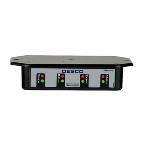
Desco 19665 Installation and operating instructions

DESCO WEST - 3651 Walnut Avenue, Chino, CA 91710 • (909) 627-8178
DESCO EAST - One Colgate Way, Canton, MA 02021-1407 • (781) 821-8370 • Website: Desco.com
TB-3019 Page 1 of 5 © 2013 DESCO INDUSTRIES, INC.
Employee Owned
Dual-Wire Dual-Operator Programmable Monitor
Installation, Operation and Maintenance
Description
The patented* Desco Dual-Wire Dual-Operator
Programmable Monitor monitors two operators and two
ESD work worksurfaces eliminating the need for periodic
testing and record keeping of wrist straps. The Dual-Wire
Dual-Operator Programmable Monitor uses low-voltage
steady state DC continuous-loop technology to continuously
monitor (versus pulsed or intermittent) dual-wire wrist strap
functionality. Independent audio and visual alarm conditions
make it easy to identify the status of the worksurfaces and
operators. Two operator remotes with 10 foot cables are
included for use at adjacent workstations. Each monitor is
calibrated with accepted procedures and standards traceable
to the National Institute of Standards and Technology (NIST)
and includes a NIST certificate.
ANSI/ESD S20.20 section 7.3 states “Compliance verification
records shall be established and maintained to provide
evidence of conformity to the technical requirements.”
Per ANSI/ESD S1.1 Annex A.3 Daily (wrist strap system)
testing may be omitted if constant monitoring used.” Per
ESD Handbook ESD TR 20.20 section 5.3.2.4.4 “Typical
Test programs recommend that wrist straps that are used
daily should be tested daily. However, if the products that
are being produced are of such value that knowledge of a
continuous, reliable ground is needed, and then continuous
monitoring should be considered or even required.”
Packaging
1 Dual-Wire Dual-Operator Programmable Monitor
1
Power Adapter, 12VDC, N. America
2 Operator Remotes
2 Operator Remote Cables (1 black, 1 white)
2 Mat Monitor Cords (1 black, 1 white)
2 Mat Ground Cords (green and yellow)
1 Monitor Ground Cord (green and yellow)
1 Universal Snap Kit
1 Certificate of Calibration
March 2013
Figure 1. Desco 19665 Dual-Wire Dual-Operator
Programmable Monitor
Features and Components
TECHNICAL BULLETIN TB-3019
Made in the
United States of America
A. Operator 1 Status LEDs: When the green LED is
illuminated, operator 1 is properly grounded. When the LED
is illuminated red or yellow and the alarm sounds, operator 1
is not properly grounded.
B. Worksurface 1 Status LEDs: When the green LED is
illuminated, worksurface 1 is properly grounded. When the
red LED is illuminated and the alarm sounds, worksurface 1
is not properly grounded.
C. Operator 2 Status LEDs: When the green LED is
illuminated, operator 2 is properly grounded. When the LED
is illuminated red or yellow and the alarm sounds, operator 2
is not properly grounded.
D. Worksurface 2 Status LEDs: When the green LED is
illuminated, worksurface 2 is properly grounded. When the
LED is illuminated red and the alarm sounds, worksurface 2
is not properly grounded.
E. Power Jack: Connect to the included 12VDC power
adapter.
Figure 2. Dual-Wire Dual-Operator Programmable
Monitor features and components
A
C
B
D
E F G H I J K L
FRONT VIEW
BACK VIEW
*U.S. Patents 6,052,053 and 6,205,408

DESCO WEST - 3651 Walnut Avenue, Chino, CA 91710 • (909) 627-8178
DESCO EAST - One Colgate Way, Canton, MA 02021-1407 • (781) 821-8370 • Website: Desco.com
TB-3019 Page 2 of 5 © 2013 DESCO INDUSTRIES, INC.
Employee Owned
F. Operator 2 Remote Jack: Connect to the black operator
remote cable.
G. Operator 1 Remote Jack: Connect to the white operator
remote cable.
H. Monitored Mat 1 Terminal: Monitors a worksurface mat
for proper dissipative resistance and static charges. Connect
the white mat monitor cord here.
I. Ground Terminal: Common ground point for the monitor.
Connect to the green and yellow monitor ground cord.
J. Monitored Mat 2 Terminal: Monitors a worksurface mat
for proper dissipative resistance and static charges. Connect
the black monitor cord here.
K. Data Output: To be used with the EMIT 50476 Smart
Hub and EMIT SIM Software for automated record keeping
of the monitor’s performance. Click here to learn more about
the EMIT SIM Software.
L. Alarm Audible Adjustment: Turn the trimpot clockwise to
increase the audible alarm volume and counter-clockwise to
decrease it.
Installation
1. Determine the mounting location of the Dual-Wire
Dual-Operator Monitor. The front panel should be visible
to both operators.
2. Determine the mounting locations of the operator
remotes. Be sure to install the remotes at a distance
that enables the 10 foot leads to reach the back of the
monitor.
3. Install tinned wire ends of the mat cords to their
appropriate screw terminal block located at the back of
the monitor.
4. Attach the worksurface mats to ground using the green
mat ground cord. Install the ring terminal end of the
cord to an appropriate ground point. Attach the
snaps terminals to the snaps on the worksurface mat.
5. Install the tinned wire end of the green and yellow
moniitor ground cord to the ground terminal located
at the back of the monitor. Install its ring terminal to an
appropriate ground point. Be sure to use a different
ground point than the one used for the mats. The face
plate screw of a grounded AC wall outlet may provide a
convenient connection point.
6. Route the mat cords from the back of the monitor to
the snaps on worksurface mats. The white cord is for
worksurface mat #1. The black cord is for worksurface
mat #2.
7. Insert the operator remote cables into their appropriate
jacks located at the back of the monitor. The white cable
is for operator #1. The black cable is for operator #2.
8. Connect the power adapter to the power jack located
at the back of the monitor. Plug the power adapter into
a proper AC power outlet. The monitor is now powered.
Operation
1. Monitoring of the operators will remain in the STANDBY
condition until a wrist cord is plugged into the operator
remote. STANDBY mode is indicated by a blinking
yellow operator LED.
2. Plug a wrist strap cord, not attached to the wristband,
into the monitored jack labeled WRIST STRAP
MONITOR located on the remote. This automatically
activates the selected operator channel. The
corresponding operator LED should illuminate red and
the alarm should sound on the monitor.
3. Remove the charges from your body by making contact
with a properly grounded ESD worksurface.
4. Snap the cord to the wristband, and fit it snugly onto
your wrist. This should silence the audible alarm and
cause the corresponding operator LED to switch from
red to green. If this does not happen, examine the wrist
cord for continuity or damage and your wrist band to
ensure that it is securely fit. If you have dry skin,
apply an approved dissipative hand lotion such as
Menda Reztore™ ESD Hand Lotion.
5. The AUX GND jack located on the operator remote
is a grounded and unmonitored connection for guests. It
must be used with a banana plug wrist cord and
single-wire wristband.
NOTE: Worksurface must have a conductive layer such as
Dual Layer Rubber or Dissipative 3-Layer Vinyl or Micastat®
Dissipative Laminate with conductive buried layers. EMIT
Continuous Monitors are not recommended for use with
homogeneous matting.
10mm snap needs to pierce
and clinch bottom side of
mat. Snap needs to be at
least 12" apart or 72" max.
10mm snap needs to pierce
and clinch bottom side of
mat. Snap needs to be at
least 12" apart or 72" max.
OPERATOR 1
WORKSURFACE
OPERATOR 2
WORKSURFACE
10mm PUSH &
CLINCH SNAP
10mm PUSH &
CLINCH SNAP
BENCH
GROUND
MAT 1 WIRING
WHITE CABLE MAT 2 WIRING
BLACK CABLE
WRIST
STRAP
MONITOR
WRIST
STRAP
MONITOR
ELECTRIC
GROUND
OPERATOR 2
REMOTE JACK
BLACK CABLE
OPERATOR 2
REMOTE JACK
WHITE CABLE
Screw allows ground cord to
be bolted to mat; keeps cord
from disconnecting.
Figure 3. Installing the Dual-Wire Dual-Operator
Programmable Monitor
oror

DESCO WEST - 3651 Walnut Avenue, Chino, CA 91710 • (909) 627-8178
DESCO EAST - One Colgate Way, Canton, MA 02021-1407 • (781) 821-8370 • Website: Desco.com
TB-3019 Page 3 of 5 © 2013 DESCO INDUSTRIES, INC.
Employee Owned
Figure 4. Connecting a dual-wire wrist strap to the
operator remote
SETTING THE OPERATOR TEST VOLTAGE AND TEST
LIMIT
The Dual-Wire Dual-Operator Monitor’s operator test voltage
and high test limit can be set to different values. The
operator test voltage can be set to either +5V or +8V, and
the operator high test limit can be set to either 10 megohms
or 35 megohms. The default voltage is +8V, and the default
operator high test limit is 10 megohms. These settings are
controlled by a set of 3 switches located inside the monitor’s
enclosure.
NOTE: Desco recommends re-calibration of the monitor
should either setting be changed. See the “Calibration”
section for more information.
To gain access to these switches, remove the monitor’s
cover and position the monitor so the PCB matches the
orientation shown in Figure 5. Switches SW1 and SW2
control the operator test voltage. Switch SW3 controls the
operator high test limit.
Operator Test Voltage
+5V
SW1 Position: RIGHT
SW2 Position: LEFT
+8V
SW1 Position: LEFT
SW2 Position: RIGHT
Operator High Test Limit
10 megohms
SW3 Position: RIGHT
35 megohms
SW3 Position: LEFT
Calibration
The
Dual-Wire Dual-Operator Programmable Monitor
is calibrated to standards traceable to NIST. Frequency of
recalibratrion should be based on the critical nature of those
ESD sensitive items handled and the risk of failure for the
ESD protective equipment and materials. In general, we
recommend that calibration be performed annually.
Use the EMIT 50524 Limit Comparator for Dual-Wire
Monitors to perform periodic testing (once every 6-12
months) of the
Dual-Wire Dual-Operator Programmable
Monitor.
The Limit Comparator can be used on the shop
floor within a few minutes virtually eliminating downtime,
verifying that the monitor is operating within tolerances.
See TB-6542 for more information.
Figure 5. Switches SW1, SW2 and SW3 inside the
monitor’s enclosure
Figure 6. EMIT
50524
Limit Comparator for Dual-Wire
Monitors

DESCO WEST - 3651 Walnut Avenue, Chino, CA 91710 • (909) 627-8178
DESCO EAST - One Colgate Way, Canton, MA 02021-1407 • (781) 821-8370 • Website: Desco.com
TB-3019 Page 4 of 5 © 2013 DESCO INDUSTRIES, INC.
Employee Owned
NIST Calibration
Desco provides a basic, National Institute of Standards
and Technology (NIST) traceable calibration for the
products that we manufacture. This is sometimes
referred to as a Level 1 calibration.
For more on National Institute of Standards and
Technology see:
http://www.nist.gov/index.html
For more information on the calibration that Desco’s
provides for products that we manufacture see:
http://desco.descoindustries.com/Calibration.aspx
Specifications
Operating Voltage 12 VDC
Operating Temperature 32°F - 104°F (0 - 40°C)
Monitor Dimensions 4.4" x 4.7" x 2.1"
(11.2cm x 11.9cm x 5.3cm)
Monitor Weight 1.1 lbs (0.5 kg)
TEST VOLTAGES
Operator +8 V** or +5 V
Worksurface 200 mV
TEST LIMITS
Operator Low Fail: < 1.72 megohms
Pass: 2 - 9 megohms**
High Fail: > 11.5 megohms**
or
Pass: 2 - 30 megohms
High Fail: > 40 megohms
Worksurface Pass: < 3.5 megohms
Fail: > 3.8 megohms
**Default
Figure 7. Operator Remote dimensions
Replacement remotes are available as EMIT item
numbers 50525 and 50526.

DESCO WEST - 3651 Walnut Avenue, Chino, CA 91710 • (909) 627-8178
DESCO EAST - One Colgate Way, Canton, MA 02021-1407 • (781) 821-8370 • Website: Desco.com
TB-3019 Page 5 of 5 © 2013 DESCO INDUSTRIES, INC.
Employee Owned
Limited Warranty
Desco expressly warrants that for a period of one (1) year from the date of purchase Desco Continuous Monitors will be free of defects in material (parts)
and workmanship (labor). Within the warranty period, a credit for purchase of replacement Desco Continuous Monitor, or, at Desco’s option, the Ionizer
Motion Sensor will be repaired or replaced free of charge. If product credit is issued, the amount will be calculated by multiplying the unused portion of
the expected one year life times the original unit purchase price. Call our Customer Service Department at 909-627-8178 (Chino, CA) or 781-821-8370
(Canton, MA) for a Return Material Authorization (RMA) and proper shipping instructions and address. Please include a copy of your original packing
slip, invoice, or other proof of date of purchase. Any unit under warranty should be shipped prepaid to the Desco factory. Warranty replacements will take
approximately two weeks.
If your unit is out of warranty, call our Customer Service Department at 909-627-8178 (Chino, CA) or 781-821-8370 (Canton, MA) for a Return Material
Authorization (RMA) and proper shipping instructions and address. Desco will quote repair charges necessary to bring your unit up to factory standards.
Warranty Exclusions
THE FOREGOING EXPRESS WARRANTY IS MADE IN LIEU OF ALL OTHER PRODUCT WARRANTIES, EXPRESSED AND IMPLIED, INCLUDING
MERCHANTABILITY AND FITNESS FOR A PARTICULAR PURPOSE WHICH ARE SPECIFICALLY DISCLAIMED. The express warranty will not apply to
defects or damage due to accidents, neglect, misuse, alterations, operator error, or failure to properly maintain, clean or repair products.
Limit of Liability
In no event will Desco or any seller be responsible or liable for any injury, loss or damage, direct or consequential, arising out of the use of or the
inability to use the product. Before using, users shall determine the suitability of the product for their intended use, and users assume all risk and liability
whatsoever in connection therewith.
Table of contents
Other Desco Monitor manuals

Desco
Desco EMIT 50513 Installation guide

Desco
Desco 19246 Instruction Manual

Desco
Desco 19226 Service manual

Desco
Desco 19239 Installation and operating instructions

Desco
Desco TB-3086 Service manual

Desco
Desco 19241 Service manual

Desco
Desco 19668 Installation and operating instructions

Desco
Desco 19325 Service manual

Desco
Desco 19228 Service manual

Desco
Desco 19234 Service manual