manuals.online logo
Brands
  1. Home
  2. •
  3. Brands
  4. •
  5. Desoutter
  6. •
  7. Controllers
  8. •
  9. Desoutter ESP 7 Operating instructions

Desoutter ESP 7 Operating instructions

TM
P
-+
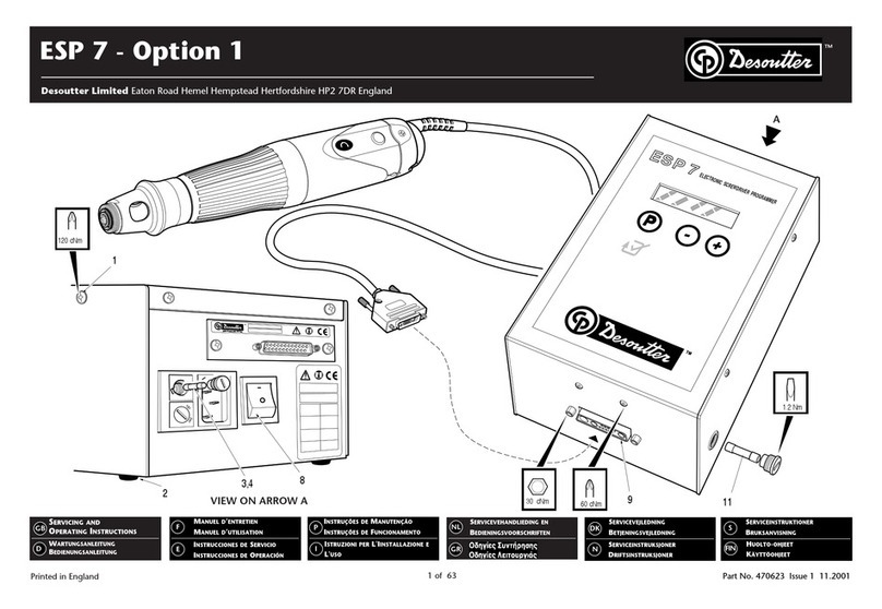
ESP7
PP
PP
ELECTRONIC SCREWDRIVER PROGRAMMER
MADE IN ENGLAND HP2 7DR
14
1 2 3 4 5 6 7 8 9 10 11 12 13
15 16 17 18 19 20 21 22 23 24 25
VIEW ON ARROW A
A
120 cNm
30 cNm 60 cNm
1.2 Nm
11
9
8
1
23,4
Printed in England 1 of 40
SERVICING AND
OPERATING INSTRUCTIONS
WARTUNGSANLEITUNG
BEDIENUNGSANLEITUNG
MANUEL D’ENTRETIEN
MANUEL D’UTILISATION
INSTRUCCIONES DE SERVICIO
INSTRUCCIONES DE OPERACIÓN
INSTRUÇÕES DE MANUTENÇÃO
INSTRUÇÕES DE FUNCIONAMENTO
ISTRUZIONI PER LA MANUTENZIONE
ISTRUZIONI OPERATIVE
SERVICEVEJLEDNING
BETJENINGSVEJLEDNING
SERVICEINSTRUKSJONER
DRIFTSINSTRUKSJONER
SERVICEINSTRUKTIONER
BRUKSANVISNING
HUOLTO-OHJEET
KÄYTTÖOHJEET
GB
D
F
E
P
I
DK
N
S
FIN
Desoutter Limited Eaton Road Hemel Hempstead Hertfordshire HP2 7DR England
ESP 7 - Option 2
TM
Part No. 476033 Issue 1 11.2001
ONDERHOUDSINSTRUCTIES
BEDIENINGSINSTUCTIES
NL
GR
OPTION BOARD
Part No. 108242-C
STATEMENT OF USE:
This control board (Part No. 108242) to be used in
conjunction with Desoutter unit ESP 7 (Part No. 111362).
No other use permitted. For professional use only.
This instruction to be used in conjunction with the ESP 7
Option 1 instructions.
Note: When fitting or removing a new option board:
1. Anti Static precautions must be taken.
2. Ensure the ESP 7 is powered Off before connecting or
disconnecting an Option Board. (Wait at least 10 seconds after
switching power off).
3.The Factory Default values must be re-loaded and parameters
changed as required afterwards.
FUNCTION - PARAMETER CHANGE MODE:
Note that a tool does not have to be connected to carry out
parameter changes.
Parameter - VALUES:
To set-up specific parameter values, depressing the mode key (P)
for3 seconds enters the parameter changemode and the following
is displayed:
If the password feature has been enabled in the “Set-Up-Routine”
described in Option 1 (i.e. Password “Yes”), the following is
displayed when the mode key is released:
If a password has been enabled enter it using up key (increased
+) or down key (decreased -). To validate the number depress
and release the mode key (P). If the wrong password is used the
unit will return to the pre-set operational mode with no parameter
changes.
Note: If no password has been selected this operation will be
bypassed and the first parameter will be presented to
the operator.
When the mode key is next depressed and released the first
parameter is presented to the user. The user can step through a
list of parameters by pressing the mode key. There is always one
parameter presented at one time. This parameter can be changed
by the up key (increased +) or down key (decreased -). By pressing
the mode key (P) a changed value is stored temporarily and the
next parameter is presented. If the mode key (P) is pressed for
greater than 3 seconds, all parameter changes are saved, the
parameter change mode is closed and the unit resumes normal
operation. The following is displayed after the 3 second period,
and disappears when the key is released.
The Set-up and the Parameter Mode will both be exited
automatically, if there is no user input for more than 60 seconds.
In this case NO changes will be stored, and the programme will
operate to the original set values.
Parameter: TOOL/MODE:
Set parameters as Basic version.
Parameter: EXTERNAL FORWARD:
The parameter can be configured as OFF, AND or ONLY and is
used in conjunction with the I/O porting.
OFF: means inactive, so only the tool start (Lever/Trigger and/or
push) will be active.
AND: means that the tools start (Lever/Trigger and/or push) and
the external signal must be supplied to start the operation.
ONLY: means that the fastening or reverse operation will be
triggered only by the corresponding external signal.
Note: If TOOL has been programmed as PUSH, the ONLY
function, although displayed, will be stored as AND. This
is intentional.
Parameter: EXTERNAL REVERSE:
The parameter can be configured as OFF, AND or ONLY and is
used in conjunction with the I/O porting.
OFF: means inactive, so only the tool Reverse (button and push)
will be active.
AND: means that the tools Reverse (button and push) and the
external signal must be supplied to start the operation.
ONLY: means that the reverse operation will be triggered only
by the corresponding external signal.
Note: If TOOL has been programmed as PUSH, the ONLY
function, although displayed, will be stored as AND. This
is intentional.
Parameter: EXTERNAL STOP:
This programme can be selected as NO or YES and is used in
conjunction with the I/O porting.
NO: means inactive.
YES: means an external signal is required to stop the fastening
(i.e. The tool is being used to position a fastener/component to
a specific position, rather than to a torque). If the clutch cut-off
operation occurs before the external signal, the tightening will
be rated as NOK (cycle not completed).
Parameter: SLOW TIME, SLOW SPEED:
If the Slow Time is selected with a value greater than 0, the
parameter slow speed will appear and a value can be selected.
The tool will start with the programmed Slow Speed and will
then switch automatically to the programmed FAST or FINAL
speed after the Slow Time has elapsed. If the Slow start is set to
0,the parameter Slow Speed will beskipped. The Slow Time/Speed
parameters apply only to the fastening operation.
Note: The Slow Phase does not function when using the HT-
Current feature, even though the Slow Time and Slow
Speeds can be programmed.
Parameter: FAST TIME, FAST SPEED:
If the Fast Time is selected with a value greater than 0, the
parameter Fast Speed will appear and a value can be selected.
The tool will run at the programmed Fast Speed and will then
switch automatically to the programmed FINAL speed after the
Fast Time has elapsed.
Note: To ensure correct tightening of fastener, the change from
Fast Speed to Final Speed must occur before the total
rundown time of the fastener.
The Fast Time/Speed parameters apply only to the fastening
operation.
Paramter: FINAL TIME, FINAL SPEED:
The Final Time and Final Speed selection will apply after the slow
and fast time (if programmed). The tool operates at this speed
until either the shut-off operation occurs or the set time if
programmed has elapsed. In non FAS mode, an "E5" message
will be displayed in the right hand digits should a "Final Time "
timeout occur before the operation has completed. In FAS mode,
an "ERR-5" message will be displayed in the second display should
a "Final Time" timeout occur before the operation is completed.
Parameter: SPEED REVERSE:
This is the speed used for reverse operation.
Printed in England
Desoutter Limited Eaton Road Hemel Hempstead Hertfordshire HP2 7DR England
ESP 7 - Option 2 Programming Description
TM
Part No. 476033 Issue 1 11.2001
2 of 40
PARAMETER MODE
PASSWORD 0
PARAMETER STORED
GB
ESP 7 - Option 2 Programming Description GB
Summary of display contents in parameter mode:
(Number in left column is Program Group number)
TO O L P U S H MANU/PUSH
MO D E P U S H PUSH/COMBI
EX T . F O RWA R D O F F OFF/AND/ONLY
EXT.REVERSE OFF OFF/AND/ONLY
EXT . STOP OF F OFF/ON
1:SLOWTIME 0.7 OFF, 0.1 . . . 9.9 sec
1 : S L OW S P E E D 4 0 % 30% . . . 100%
1:FASTTIME 0.7 OFF, 0.1 . . . 9.9 sec
1 : F A S T S P E E D 8 0% 30% . . . 100%
1 : F I N A L T I M E 5 . 0 OFF, 0.1 . . . 9.9 sec
1: FINALSPEED 30% 30% . . . 100%
1:REVERSE 60% 30% . . . 100%
1/0 Signals:
The option modules add the following digital input/output
capabilities to the system.
IN: EXTERNAL FORWARD IN: EXTERNAL REVERSE
IN: EXTERNAL STOP.
OUT: CYCLE COMPLETE (OK), same operation as LED on front panel.
OUT: NOT COMPLETED (NOK).
Functionality of Inputs:
EXTERNAL FORWARD and EXTERNAL REVERSE are for external
operation of the tool.
EXTERNAL STOP NO/YES.When "External Stop" is programmed
YES, this input will cause the tool to stop.
Functionality of Outputs:
The outputs are switched inactive with every trigger operation,
which sets the tool into Forward motion.
The OK (Cycle Complete) or NOK (Not Completed) will be
rated by the following:
A tightening finished by a valid clutch operation will be rated
as OK.
Signals on the I/0 connector:
WARNING: A valid clutch operation requires that the tool is
held firmly against the fastener throughout the operation and
for the tightening to be completed within the Final Time period.
(If programmed). For further information, refer to "Explanation
of status of Green OK "LED" in ESP 7 Programming Description
- Option 1.
All other results will show a NOK display.
Note: An external 24V power supply is required to enable the External
Input and Output signals.
Maximum output current per output is 500mA.
Current per input is 9mA.
LSignal level required for time period indicated.
PCan be a Pulse with a minimum time duration of 200ms, however
if longer the External Stop must be disabled before the start of the
next cycle. Note that signals Reset Last, Reset All and NOK Receipt
are rising edge triggered. While they can be low or high at the start
of the next cycle, to be used at the end of it, they must be first
disabled and then enabled.
© Copyright 2001, Desoutter, HP2 7DR, UK.
All rights reserved. Any unauthorized use or copying of the contents
or part thereof is prohibited. This applies in particular to trademarks,
model denominations, part numbers and drawings.
Use only authorized parts. Any damage or malfunction caused
by the use of unauthorized parts is not covered by Warranty or
Product Liability.
Printed in EnglandPrinted in England
Desoutter Limited Eaton Road Hemel Hempstead Hertfordshire HP2 7DR England
Part No. 476033 Issue 1 11.2001
3 of 40
TM
Signal I/O Pin/common Description Signal Signal Duration
connections Type
EXTERNAL Input 21 Signal to run tool forward, can be used L 24V signal
FORWARD exclusive or together with the tool button. Must be enabled when Ext Forward = And or Only
EXTERNAL Input 22 Signal to run tool in reverse, can be used L 24V signal
REVERSE exclusive or together with the tool button. Must be enabled when Ext Reverse = And or Only
EXTERNAL Input 12 Allows immediate stop of tool (depth P 24V signal. See Note below.
STOP sensor, park position)
CYCLE Output 2/15 Signals that the fastening is complete - L 24V signal
COMPLETED i.e. clutch has fired or current shutoff Signal remains enabled until start of next
(OK) has fired tightening cycle (not reverse) or ESP is powered off
NOT Output 1/14 Signals that the tool has stopped, but L 24V signal
COMPLETED fastening was not successful. Signal remains enabled until start of next
(NOK) tightening cycle (not reverse) or ESP is powered off
+24V 5/18 24V from external power supply L Required for all External I/O operations
0V 6/7/13/19 0V return to external power supply L Required for all External I/O operations
20/25
ESP 7 - Option 2 Programming Description GB
Printed in EnglandPrinted in England
Desoutter Limited Eaton Road Hemel Hempstead Hertfordshire HP2 7DR England
Part No. 476033 Issue 1 11.2001
4 of 40
TM
Pin 4/17: Output signal (L See Note). n Screws OK Signals that a
complete Group of screws has been completed successfully, or Reset
All signal has been enabled. Signal remains enabled until start of first
cycle of the next Group, End of Programming or ESP is powered off.
Note that this signal is also Enabled when Reset All is used.
Pin 3/16: Output signal (L See Note) n Screws NOK Signals that a
complete Group of screws has been completed, but not successfully.
Signal available until Reset Last; Reset All; End of Programming or ESP
is powered off.
Pin 2/15: Output signal (L See Note).
Cycle Completed (OK) Signals that the fastening is complete- i.e.
clutch has fired or current shutoff has occurred.
Signal remains enabled until start of next tightening cycle
(Not Reverse) or ESP is powered off.
Pin 1/14: Output signal (L See Note).
Not Completed (NOK) Signals that the tool has stopped, but
fastening was not successful.
Signal remains enabled until start of next tightening cycle
(Not Reverse) or ESP is powered off.
Pins 5 and 18: +24V frorn external power supply.
Required for all External 1/0 operations.
Pin 8: Input Signal (L See Note). External Group Start for FAS
operation. If Group Start programmed Ext, this signal must be enabled
for all operations. Note that it can be enabled / disabled by external
control before each Group start (I.e. Use as an external " Master
Enable " signal).
Pin 21: Input Signal (L See Note).
External Forward Signal to run tool forward, can be used exclusive or
together with the tool button signal. Must be enabled when Ext
Forward = And or Only.
Pin 22: Input Signal (L See Note).
External Reverse Signal to run tool in reverse, can be used exclusive
or together with the tool button signal. Must be enabled when Ext
Reverse = And or Only.
Pins 6/7/13/19/20/25: Common 0V return to external power supply.
Required for all External l/0 operations.
Pin 12: Input Signal (PSee Note). External Stop.
Allows immediate stop of tool (depth sensor, park position).
See Note below.
Pin 11: Input Signal (P See Note). Reset Last.
1. Resets last screw within current Cycle.
2. Used with Reset All in Sequence Mode to return to first Valid Group
Pin 9: Input Signal (P See Note).
NOK Receipt Resets NOK of last result.
NOTE, An external 24V power supply is required to enable the External Input and Output signals. Maximum output current per output is 500mA. Current per Input is 9mA.
L: +24V Signal level required for time period indicated.
P: +24V Can be a Pulse with a minimum time duration of 200ms, however if longer, External Stop must be disabled before the start of the next cycle.
Note that signals Reset Last, Reset All and NOK Receipt are rising edge triggered. While they can be low or high at the start of the next cycle, to be used at the end of it,
they must be first disabled and then enabled.
Pins of Ext I/O Pin D 25 Pin D type connector as viewed from rear of ESP 7 Controller
14
1 2 3 4 5 6 7 8 9 10 11 12 13
15 16 17 18 19 20 21 22 23 24 25

Other Desoutter Controllers manuals

Desoutter CVIR II User manual

Desoutter

Desoutter CVIR II User manual

Desoutter CVIC II Series User manual

Desoutter

Desoutter CVIC II Series User manual

Desoutter ESP1-HT PLUS User manual

Desoutter

Desoutter ESP1-HT PLUS User manual

Desoutter CVI3 Function User manual

Desoutter

Desoutter CVI3 Function User manual

Desoutter Industrial Tools CVIC II L2 User manual

Desoutter

Desoutter Industrial Tools CVIC II L2 User manual

Desoutter CVIL II User manual

Desoutter

Desoutter CVIL II User manual

Desoutter CVI3 Vision User manual

Desoutter

Desoutter CVI3 Vision User manual

Desoutter CVIC II User manual

Desoutter

Desoutter CVIC II User manual

Desoutter CVI3 Series Quick start guide

Desoutter

Desoutter CVI3 Series Quick start guide

Desoutter ESP-C 110 V User manual

Desoutter

Desoutter ESP-C 110 V User manual

Desoutter CVI3 Essential Manual

Desoutter

Desoutter CVI3 Essential Manual

Desoutter ESP-CA 230 User manual

Desoutter

Desoutter ESP-CA 230 User manual

Desoutter Industrial Tools ESP2-A User manual

Desoutter

Desoutter Industrial Tools ESP2-A User manual

Desoutter ESP1-A User manual

Desoutter

Desoutter ESP1-A User manual

Desoutter CVI3 Essential Instruction sheet

Desoutter

Desoutter CVI3 Essential Instruction sheet

Desoutter FAS3000 User manual

Desoutter

Desoutter FAS3000 User manual

Desoutter ESP 7 Operating instructions

Desoutter

Desoutter ESP 7 Operating instructions

Desoutter CVIC II L2 User manual

Desoutter

Desoutter CVIC II L2 User manual

Popular Controllers manuals by other brands

Contrec 515 Operation manual

Contrec

Contrec 515 Operation manual

Lumenpulse Lumenstudio user manual

Lumenpulse

Lumenpulse Lumenstudio user manual

Nidec LEROY-SOMER R221 Installation and Maintenance

Nidec

Nidec LEROY-SOMER R221 Installation and Maintenance

MOGlabs FSC100 manual

MOGlabs

MOGlabs FSC100 manual

Aimco AcraDyne Gen IV iAC Operation manual

Aimco

Aimco AcraDyne Gen IV iAC Operation manual

MESHLE 007T-1 quick start guide

MESHLE

MESHLE 007T-1 quick start guide

Opera 6000 series Operation manual

Opera

Opera 6000 series Operation manual

EUCHNER CEM-A Series operating instructions

EUCHNER

EUCHNER CEM-A Series operating instructions

White Rodgers 50A55-143 user manual

White Rodgers

White Rodgers 50A55-143 user manual

Maxim MAX3421E Programming guide

Maxim

Maxim MAX3421E Programming guide

Mitel MiVoice Office 400 System manual

Mitel

Mitel MiVoice Office 400 System manual

SMSC USB2513 datasheet

SMSC

SMSC USB2513 datasheet

RKC INSTRUMENT PF900 Quick operation manual

RKC INSTRUMENT

RKC INSTRUMENT PF900 Quick operation manual

THORLABS LCC25 operating manual

THORLABS

THORLABS LCC25 operating manual

NEC N8190-157 user guide

NEC

NEC N8190-157 user guide

CKD AX1000T Series manual

CKD

CKD AX1000T Series manual

TECH EU-RP-3 user manual

TECH

TECH EU-RP-3 user manual

3M Touch Screen Controller RX142 reference guide

3M

3M Touch Screen Controller RX142 reference guide

manuals.online logo
manuals.online logoBrands
  • About & Mission
  • Contact us
  • Privacy Policy
  • Terms and Conditions

Copyright 2025 Manuals.Online. All Rights Reserved.