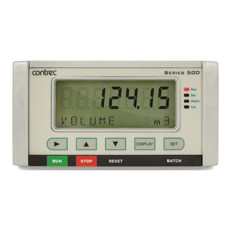
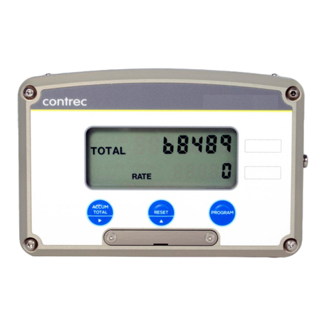
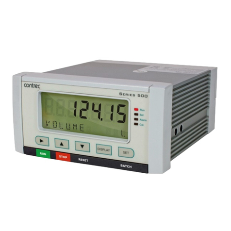
Contrec 515 User manual

Model 515 Flow Computer
Operation Manual
Application BS03
Secure Dual Stage Batch Controller
for
Mass Frequency Flowmeters
2 April 2017

Model 515 Flow Computer - Operation Manual
© Contrec Limited 2017
The instructions given herein cover the general description, installation, operation and maintenance of the subject
equipment. Contrec Limited. reserves the right, without prior notice, to make engineering refinements that may not
be reflected in this manual.
Should any questions arise which cannot be answered specifically by this manual, they should be directed to
Contrec Limited for further detailed information and technical assistance.
Contrec Limited will not accept any liability for either direct or consequential damages resulting from the use or
misapplication of the contents of this manual.
Part of the software embedded in this product is eCos - Embedded Configurable Operating System, a trademark of
Red Hat. Portions created by Red Hat are Copyright © 1998, 1999, 2000 Red Hat, Inc.
(http://www.redhat.com). All rights reserved
The software in this product was in part provided by Red Hat and any express or implied warranties, including, but
not limited to, the implied warranties of merchantability and fitness for a particular purpose are disclaimed. In no
event shall the author be liable for any direct, indirect, incidental, special, exemplary, or consequential damages
(including, but not limited to, procurement of substitute goods or services; loss of use, data, or profits; or business
interruption) however caused and on any theory of liability, whether in contract, strict liability, or tort (including
negligence or otherwise) arising in any way out of the use of this software, even if advised of the possibility of such
damage. Contrec Limited
Riverside, Canal Road, Sowerby Bridge,
West Yorkshire HX6 2AY UNITED KINGDOM
Tel: +44 1422 829944 Fax: +44 1422 829945
Email: [email protected]
Website: www.contrec.co.uk
Contrec Systems Pty Ltd
5 Norfolk Avenue Ringwood, Melbourne 3134 AUSTRALIA
Tel: +61 4 413 505 114
Email: [email protected]
Contrec - USA, LLC
916 Belcher Drive Pelham AL 35124 USA
Tel: +1 (205) 685 3000 Fax: +1 (205) 685 3001
Email: [email protected]
Publication No: 515-BS03-OM - 2 April 2017

515 BS03 - 2 April 2017 iii
Safety Notice
The information in this safety notice is for the prevention of injury to personnel and
damage to the instrument.
The manufacturer assumes no liability for injury or damage caused by misuse of the
instrument or for modifications made to the instrument.
Qualified Personnel
The instrument must be installed, operated and serviced by persons who have been properly
trained and authorised. Personnel must read and understand this manual prior to installation and
operation of the instrument.
Static Hazard
The 500 series flow computer uses high speed CMOS circuitry which is sensitive to static
damage. The user should observe accepted safety practices for handling electronic devices,
especiallyduringservicing.Oncetheunitisinstalled,groundedandinterconnected,thechances
of static damage are greatly reduced.
Voltage Hazard
Before connecting power to the instrument, ensure that the supply voltage for the AC or DC
input is suitable. The AC voltage rating is as stated on the instrument rating plate. Personnel
should take all due care to avoid electric shock.
Welding Hazard
Do not perform electric welding in close proximity to the instrument or its interconnecting
cables. If welding in these areas must be performed, disconnect all cables from the instrument.
Failure to do so may result in damage to the unit.
Moisture Hazard
To avoid electrical faults and corrosion of the instrument, do not allow moisture to remain in
contact with the instrument.
Disconnection Device
When powered from a mains supply this unit requires the provision of a suitable mains isolation
device to be accessible near to the installed instrument.
515 BS03 - 2 April 2017

iv 515 BS03 - 2 April 2017

v
1 Introduction
Features . . . . . . . . . . . . . . . . . . . . . . . . . . . . . . . . . . . . . . . . . . 1
Overview . . . . . . . . . . . . . . . . . . . . . . . . . . . . . . . . . . . . . . . . . . 1
Calculations . . . . . . . . . . . . . . . . . . . . . . . . . . . . . . . . . . . . . . . 2
Displayed Information . . . . . . . . . . . . . . . . . . . . . . . . . . . . . . . . . 2
Main Menu Variables . . . . . . . . . . . . . . . . . . . . . . . . . . . . . . . . . . 2
Communications . . . . . . . . . . . . . . . . . . . . . . . . . . . . . . . . . . . . 3
Isolated Outputs . . . . . . . . . . . . . . . . . . . . . . . . . . . . . . . . . . . . 3
Relay Outputs . . . . . . . . . . . . . . . . . . . . . . . . . . . . . . . . . . . . . . 3
Software Configuration . . . . . . . . . . . . . . . . . . . . . . . . . . . . . . . . . 3
Specialised Uses . . . . . . . . . . . . . . . . . . . . . . . . . . . . . . . . . . . . 4
Approvals . . . . . . . . . . . . . . . . . . . . . . . . . . . . . . . . . . . . . . . . 5
2 Specifications
Specification Table . . . . . . . . . . . . . . . . . . . . . . . . . . . . . . . . . . . . 7
3 Installation
Panel Mounting . . . . . . . . . . . . . . . . . . . . . . . . . . . . . . . . . . . . . . 9
Electrical Connection . . . . . . . . . . . . . . . . . . . . . . . . . . . . . . . . . . 10
Rear Panel Connections . . . . . . . . . . . . . . . . . . . . . . . . . . . . . . . 10
Terminal Designations . . . . . . . . . . . . . . . . . . . . . . . . . . . . . . . . 10
Inputs . . . . . . . . . . . . . . . . . . . . . . . . . . . . . . . . . . . . . . . . . . 11
Frequency Input Connection . . . . . . . . . . . . . . . . . . . . . . . . . . . . . 11
Logic Input Connection . . . . . . . . . . . . . . . . . . . . . . . . . . . . . . . 12
Outputs . . . . . . . . . . . . . . . . . . . . . . . . . . . . . . . . . . . . . . . . . . 12
4-20mA Output Connection . . . . . . . . . . . . . . . . . . . . . . . . . . . . . 12
Digital Output Connection . . . . . . . . . . . . . . . . . . . . . . . . . . . . . . 13
Control Relays (Alarms) . . . . . . . . . . . . . . . . . . . . . . . . . . . . . . . . . 13
RC Network for Interference Suppression . . . . . . . . . . . . . . . . . . . . . . 14
Communications . . . . . . . . . . . . . . . . . . . . . . . . . . . . . . . . . . . . . 15
RS-232 Port . . . . . . . . . . . . . . . . . . . . . . . . . . . . . . . . . . . . . . 15
RS-485 Port (Optional) . . . . . . . . . . . . . . . . . . . . . . . . . . . . . . . . 15
Earthing and Shielding . . . . . . . . . . . . . . . . . . . . . . . . . . . . . . . . 16
4 Operation
Front Panel Operation . . . . . . . . . . . . . . . . . . . . . . . . . . . . . . . . . . 17
Default Variable . . . . . . . . . . . . . . . . . . . . . . . . . . . . . . . . . . . 18
Status LEDs . . . . . . . . . . . . . . . . . . . . . . . . . . . . . . . . . . . . . . 18
Front Panel Keys . . . . . . . . . . . . . . . . . . . . . . . . . . . . . . . . . . . 18
Main Menu Items . . . . . . . . . . . . . . . . . . . . . . . . . . . . . . . . . . . 19
Setting the Batch Preset . . . . . . . . . . . . . . . . . . . . . . . . . . . . . . . 19
Data Logs . . . . . . . . . . . . . . . . . . . . . . . . . . . . . . . . . . . . . . . 20
Contents
515 BS03 - 2 April 2017

vi 515 BS03 - 2 April 2017
Model Information . . . . . . . . . . . . . . . . . . . . . . . . . . . . . . . . . . 21
Batch Operation Modes . . . . . . . . . . . . . . . . . . . . . . . . . . . . . . . . . 22
Preset Mode . . . . . . . . . . . . . . . . . . . . . . . . . . . . . . . . . . . . . . 22
On-Off Mode . . . . . . . . . . . . . . . . . . . . . . . . . . . . . . . . . . . . . 22
Unload Mode . . . . . . . . . . . . . . . . . . . . . . . . . . . . . . . . . . . . . 23
Batch Operation . . . . . . . . . . . . . . . . . . . . . . . . . . . . . . . . . . . . . 23
Safety and Security . . . . . . . . . . . . . . . . . . . . . . . . . . . . . . . . . . 23
Starting a Batch . . . . . . . . . . . . . . . . . . . . . . . . . . . . . . . . . . . . 24
Stopping a Batch . . . . . . . . . . . . . . . . . . . . . . . . . . . . . . . . . . . 24
Resetting a Batch . . . . . . . . . . . . . . . . . . . . . . . . . . . . . . . . . . . 25
Printing a Delivery Docket . . . . . . . . . . . . . . . . . . . . . . . . . . . . . . 25
Logic Input Control . . . . . . . . . . . . . . . . . . . . . . . . . . . . . . . . . 26
Batch Flow Errors . . . . . . . . . . . . . . . . . . . . . . . . . . . . . . . . . . . 26
Batch Control Processes . . . . . . . . . . . . . . . . . . . . . . . . . . . . . . . 27
5 Instrument Calibration
Introduction . . . . . . . . . . . . . . . . . . . . . . . . . . . . . . . . . . . . . . . 29
Calibration View Mode . . . . . . . . . . . . . . . . . . . . . . . . . . . . . . . . . 29
Calibration Set Mode . . . . . . . . . . . . . . . . . . . . . . . . . . . . . . . . . . 30
Changing the Instrument Settings . . . . . . . . . . . . . . . . . . . . . . . . . . 31
Calibration Menu Tree . . . . . . . . . . . . . . . . . . . . . . . . . . . . . . . . . . 32
Instrument Settings . . . . . . . . . . . . . . . . . . . . . . . . . . . . . . . . . . . . 34
Units of Measurement . . . . . . . . . . . . . . . . . . . . . . . . . . . . . . . . 34
Parameters . . . . . . . . . . . . . . . . . . . . . . . . . . . . . . . . . . . . . . 35
Inputs . . . . . . . . . . . . . . . . . . . . . . . . . . . . . . . . . . . . . . . . . 37
Outputs . . . . . . . . . . . . . . . . . . . . . . . . . . . . . . . . . . . . . . . . 41
Alarms . . . . . . . . . . . . . . . . . . . . . . . . . . . . . . . . . . . . . . . . 43
Communications . . . . . . . . . . . . . . . . . . . . . . . . . . . . . . . . . . . 44
Time Settings and Data Logging . . . . . . . . . . . . . . . . . . . . . . . . . . . 46
General Setup Parameters . . . . . . . . . . . . . . . . . . . . . . . . . . . . . . . 48
Test Menu . . . . . . . . . . . . . . . . . . . . . . . . . . . . . . . . . . . . . . . 50
System Messages . . . . . . . . . . . . . . . . . . . . . . . . . . . . . . . . . . . . . 51
Error Messages . . . . . . . . . . . . . . . . . . . . . . . . . . . . . . . . . . . . 52
Warning Messages . . . . . . . . . . . . . . . . . . . . . . . . . . . . . . . . . . 53
Prompt Messages . . . . . . . . . . . . . . . . . . . . . . . . . . . . . . . . . . . 53
6 Communications
Overview . . . . . . . . . . . . . . . . . . . . . . . . . . . . . . . . . . . . . . . . . 55
Hardware Interconnection . . . . . . . . . . . . . . . . . . . . . . . . . . . . . . 55
Protocols . . . . . . . . . . . . . . . . . . . . . . . . . . . . . . . . . . . . . . . . . 57
Simple ASCII Protocol . . . . . . . . . . . . . . . . . . . . . . . . . . . . . . . . . 57
Requests Format . . . . . . . . . . . . . . . . . . . . . . . . . . . . . . . . . . . 58
Instrument Responses . . . . . . . . . . . . . . . . . . . . . . . . . . . . . . . . . 59
Corrupted or Invalid Requests . . . . . . . . . . . . . . . . . . . . . . . . . . . . 62
Modbus RTU Protocol . . . . . . . . . . . . . . . . . . . . . . . . . . . . . . . . . 63
List of Data Registers . . . . . . . . . . . . . . . . . . . . . . . . . . . . . . . . . 64
iButton ID Tag Protocol . . . . . . . . . . . . . . . . . . . . . . . . . . . . . . . . . 70
Printer Protocol . . . . . . . . . . . . . . . . . . . . . . . . . . . . . . . . . . . . . 71

515 BS03 - 2 April 2017 vii
Types of Printouts . . . . . . . . . . . . . . . . . . . . . . . . . . . . . . . . . . 71
Printer Data Control . . . . . . . . . . . . . . . . . . . . . . . . . . . . . . . . . 74
Appendix A Glossary
Glossary . . . . . . . . . . . . . . . . . . . . . . . . . . . . . . . . . . . . . . . . . 77
Appendix B Model Numbers
Product Codes . . . . . . . . . . . . . . . . . . . . . . . . . . . . . . . . . . . . . . 79
Custom Version Codes . . . . . . . . . . . . . . . . . . . . . . . . . . . . . . . . . 80
Application Information Code . . . . . . . . . . . . . . . . . . . . . . . . . . . . . . 80
Appendix C Units of Measurement
Available Units of Measurement . . . . . . . . . . . . . . . . . . . . . . . . . . . . 82
Index . . . . . . . . . . . . . . . . . . . . . . . . . . . . . . . . . . . . . . . . . . . . 83

viii 515 BS03 - 2 April 2017

ix515 BS03 - 2 April 2017
List of Figures
1 Typical Application Diagram . . . . . . . . . . . . . . . . . . . . . . . . . . . . 4
2 500 Series Instrument Panel Mounting . . . . . . . . . . . . . . . . . . . . . . . 9
3 Rear Panel Connections . . . . . . . . . . . . . . . . . . . . . . . . . . . . . . 10
4 Logic Inputs Connection Diagram . . . . . . . . . . . . . . . . . . . . . . . . 12
5 Output 4-20mA Connection Diagram . . . . . . . . . . . . . . . . . . . . . . . 13
6 Output Pulse Connection Diagram . . . . . . . . . . . . . . . . . . . . . . . . 13
7 Relay Connection Diagram . . . . . . . . . . . . . . . . . . . . . . . . . . . . 14
8 RS-485 Interface Connections . . . . . . . . . . . . . . . . . . . . . . . . . . . 16
9 Batch Operation with Manual or Automatic Reset . . . . . . . . . . . . . . . . 27
10 Batch Operation with Automatic Restart . . . . . . . . . . . . . . . . . . . . . 28
11 Calibration Menu Tree Sheet 1 . . . . . . . . . . . . . . . . . . . . . . . . . . 32
12 Calibration Menu Tree Sheet 2 . . . . . . . . . . . . . . . . . . . . . . . . . . 33
13 RS-232 Cable Connections to a Computer . . . . . . . . . . . . . . . . . . . . 56
14 RS-485 Connections
. . . . . . . . . . . . . . . . . . . . . . . . . . . . . . . . 56

x 515 BS03 - 2 April 2017

1
Chapter 1
Introduction
Features •Tailored for mass frequency flow inputs
•Single or Dual stage control
•Unload, Preset or manual On-Off modes
•Special quadrature flow input feature allows for forward and reverse
totalising in On-Off batch mode
•Quick access to common batch quantities
•No-flow, leakage and overflow error detection
•Remote RUN/STOP/RESET
•Allows for permissive with prompt
•ID Tag validation, security and storage
•Allows for non-linear correction
•Storage of 1000 transactions with time and date stamp
•Selection of second language and user tags
•Pulse width and scaling of pulse output
•4-20mA retransmission
•Selectable protocols on serial ports including Modbus RTU and Printer
output
•Front panel adjustment of 8-24V DC output voltage
•Backlit display with LCD backup
Overview
The 515 BS03 application is a secure dual stage batch controller for
reliable measurement of preset quantities using a mass frequency input. The
instrument can be set to accept a valid ID-Tag, via an ‘iButton’ reader on the
serial port and/or prompt for connection of a permissive before a batch can
be commenced.
515 BS03 - 2 April 2017

Introduction
2 515 BS03 - 2 April 2017
It provides the operator with clear prompts and local readout. The ID-Tag
number is stored as a part of the logged transaction record and can be used
to link deliveries to external databases. Standard 500 Series batching
features such as automatic overrun compensation, quick access to common
presets and flow timeouts are included.
The instrument is compatible with a wide range of flowmeter frequency
outputs, including millivolt signals, reed switches, Namur proximity
switches and pulse trains via its smart front-panel program selection.
Calculations
The total and flowrate are derived from accurately measured frequency and
the number of received pulses.
mass = pulses / k-factor
mass flow = frequency / k-factor
Automatic overrun compensation calculates the new valve closure point to
ensure correct delivery by averaging the overrun amount from the last three
complete batches.
Theoverruncompensationvalue is valid for a new preset value provided the
stored overrun is less than 20% of the new preset.
Displayed Information
The front panel display shows the current values of the input variables and
the results of the calculations.
The instrument can be supplied with a real-time clock for storage of up to
1000 transactions with time and date stamps.
Main Menu Variables
Refer to Available Units of Measurement on page 82 for the list of
available units.
Main Menu
Variables Default
Units Variable
Type
Mass kg Total
Mass Flowrate kg/min Rate
Batch ID Tag - - - - - -

Introduction
515 BS03 - 2 April 2017 3
Communications
There are two communication ports available as follows:
•RS-232 port
•RS-485 port (optional)
The ports are available for remote data reading, printouts and for initial
application loading of the instrument.
Isolated Outputs
The opto-isolated outputs can retransmit any main menu variable. The type
of output is determined by the nature of the assigned variable. Totals are
output as pulses and rates are output as 4-20mA signals. One output is
standard, a second output is available as an option.
Relay Outputs
The relay outputs 1 and 2 are used to control the flow of product for each
delivery. These contacts are normally open and can be used to drive external
relays, valves, pump circuits etc. The advanced option provides another two
relays that can be used as fully programmable alarms for any rate type
variable.
Software Configuration
The instrument can be further tailored to suit specific application needs
including units of measurement, custom tags, second language or access
levels. A distributor can configure these requirements before delivery.
Instrument parameters including units of measurement can be programmed
in the field, according to the user access levels assigned to parameters by the
distributor.
All set-up parameters, totals and logged data are stored in non-volatile
memory with at least 30 years retention.

Introduction
4 515 BS03 - 2 April 2017
Figure 1 Typical Application Diagram
Specialised Uses
On-Off Loading with a Quadrature Flowmeter
A quadrature pulse input is available on this instrument that operates as a
pulse security feature. When the instrument is programmed to operate in
ON-OFF batch mode it also allows the detection of flow direction which
allows for on and off loading with just one flowmeter.
When quadrature input is enabled and ON-OFF batch mode is selected, the
instrument will automatically count up or down depending on the direction
of flow detected. At the end of the delivery the batch total will show the net
amountofproductdelivered.Ifproduct is ‘loaded’ina forward directionthe
overall batch total will be positive. If the intention is to ‘off-load’ product
by reversing the flow, the overall batch total will be negative. The negative
sign on the totals are shown on print outs and logged data to indicate if the
delivery was ‘on-loaded or off-loaded’.
The instrument caters for applications where there is the possibility of
product flowing in either direction during a delivery or transfer. This
includes examples such as back draining of supply lines at the end of a
delivery. In this case the display would show the back draining product
being deducted from the current net batch total.
In On-Off mode the operator determines the start and end of the delivery by
using the front or remote keys.
Main Flow
Control Valve
Bleed Flow
Relay 1 Relay 2
Control Valve
Example of
dual stage
batching
Mass
Flowmeter

Introduction
515 BS03 - 2 April 2017 5
Quadrature Input Check
When enabled, the two pulse trains from the quadrature flowmeter should
be supplied to frequency inputs 1 and 2. In ON-OFF batch mode the
instrument will check the phase of the two inputs to determine if channel 1
or channel 2 is leading which allows the instrument to determine the
direction of flow. For forward counting flow channel 1 should lead channel
2 by approx 90 degrees phase shift and for reverse counting flow channel 2
should lead channel 1 by approx 90 degrees.
The instrument also checks for simultaneous pulses, missing pulses on
channel 1 and missing pulses on channel 2. If more than two errors, of one
of these fault types, occur within 4000 pulses the instrument will raise a
quadrature input exception.
Quadrature Cutoff Frequency
Due to the varying sensitivity of sensors in quadrature flowmeters
(especially pickup coils in turbine meters) it is possible to get pulse errors at
very low flowrates (frequency) during start up and change of directions. For
this reason, the instrument includes a CUTOFF for the QUAD input
(entered in Hz) that will ignore any of the errors mentioned above and will
not totalise below the programmed cutoff. This cutoff has a minimum of
10Hz and can be programmed up to 100Hz. The cutoff value should be set
safely below the flowmeters minimum specified operating range so as not
to ignore any valid flow. Any detected flowrate on channel 1 will still be
displayed below the quadrature cutoff frequency.
Pulse security checking is performed from the preprogrammed cutoff
frequencyupto a maximum frequency of 3 kHz. Anexceptionwillbe raised
if the maximum frequency is exceeded. The flow calculations are always
based on the pulses received on frequency input channel 1, while channel 2
is used to determine the phase and therefore direction of flow and totalising.
Approvals This instrument conforms to the EMC-Directive of the Council of
European Communities 2004/108/EC, the LVD directive 2006/95/EC and
the following standards:
•EN61326:2013 Electrical equipment for measurement, control and
laboratory use – EMC requirements:
Residential, Commercial & Light Industry Environment & Industrial
Environment.
•EN61010:2010 Safety requirements for electrical equipment for
measurement, control, and laboratory use.
In order to comply with these standards, the wiring instructions in Chapter
3 - Installation must be followed.

Introduction
6 515 BS03 - 2 April 2017

7
Chapter 2
Specifications
Specification Table
Operating Environment
Temperature -20°C to +60°C (conformal coating)
+5°C to +40°C (no coating)
Humidity 0 to 95% non condensing (conformal
coating)
5% to 85% non condensing (no coating)
Power Supply 100-240 V AC (+/-10%) 50-60 Hz (+/-
10%) or 12-28 V DC
Consumption 6W (typical)
Protection Sealed to IP65 (Nema 4X) when panel
mounted
Dimensions 147mm (5.8") width
74mm (2.9") height
167mm (6.6") depth
Display
Type Backlit LCD with 7-digit numeric display
and 11-character alphanumeric display
Digits 15.5mm (0.6") high
Characters 6mm (0.24") high
LCD Backup Last data visible for 15min after power
down
Update Rate 0.3 second
Non-volatile Memory
Retention > 30 years
Data Stored Setup, Totals and Logs
Approvals
Interference compliance
Enclosure ATEX, FM, CSA and SAA approved
enclosures available for hazardous areas
Real Time Clock (Optional)
Battery Type 3 volts Lithium button cell (CR2032)
Battery Life 5 years (typical)
Frequency Input (General)
Range 0 to 10kHz (3kHz for pulse security)
Overvoltage 30V maximum
Update Time 0.3 sec
Cutoff frequency Programmable
Configuration Pulse, coil or NPS input
Non-linearity Up to 10 correction points
Pulse
Signal Type CMOS, TTL, open collector, reed switch
Threshold 1.3 volts
Coil
Signal Type Turbine and sine wave
Sensitivity 15mV p-p minimum
NPS
Signal Type NPS sensor to Namur standard
Logic Inputs
Signal Type CMOS, TTL, open collector, reed switch
Overvoltage 30V maximum
Relay Output
No. of Outputs 2 relays plus 2 optional relays
Voltage 250 volts AC, 30 volts DC maximum
(solid state relays use AC only)
Current 3A maximum
Communication Ports
Ports RS-232 port
RS-485 port (optional)
Baud Rate 2400 to 19200 baud
Parity Odd, even or none
Stop Bits 1 or 2
Data Bits 8
Protocols ASCII, Modbus RTU, Printer*, ID-Tag
515 BS03 - 2 April 2017

Specifications
8 515 BS03 - 2 April 2017
Important: Specifications are subject to change without notice.
Printer protocol is available only if RTC option is installed.
Transducer Supply
Voltage 8 to 24 volts DC, programmable
Current 70mA @ 24V, 120mA @ 12V maximum
Protection Power limited output
Isolated Output
No. of Outputs 1 configurable output (plus 1 optional)
Configuration Pulse/Digital or 4-20mA output
Pulse/Digital Output
Signal Type Open collector
Switching 200mA, 30 volts DC maximum
Saturation 0.8 volts maximum
Pulse Width Programmable: 10, 20, 50, 100, 200 or
500ms
4-20mA Output
Supply 9 to 30 volts DC external
Resolution 0.05% full scale
Accuracy 0.05% full scale (20C)
0.1% (full temperature range, typical)

9
Chapter 3
Installation
Panel Mounting
The instrument should be located in an area with a clean, dry atmosphere
that is also relatively free of shock and vibration.
The standard mounting procedure is panel mounting in a cutout that is
139mm wide by 67mm high. Two side clips secure the unit into the panel.
Figure 2 shows the panel mounting requirements for the 500 Series
Instrument.
Figure 2 500 Series Instrument Panel Mounting
145mm
Side View
22mm
70mm
67mm
139mm
25mm
66mm
Min. 189mm
Panel Cut-out
Front
Panel
74mm
Mounting Clip
138mm
147mm
Rear Connectors Top View RS232
Port
515 BS03 - 2 April 2017

Installation
10 515 BS03 - 2 April 2017
Electrical Connection
Rear Panel Connections
Figure 3 shows the connections on the rear panel of the instrument.
Figure 3 Rear Panel Connections
Terminal Designations
RS232 Port
CAUTION
MAINS
E N A
AC MAINS
19 20 21 22 23 24 25 26 27 28 29 30 31 32 33 34 35
RC R1 R2 R3 R4
RELAYS
+ - G1+2+3+4+C- + - + -
RS485 LOGIC INPUT OUT1 OUT2
1 2 3 4 5 6 7 8 9 10 11 12 13 14 15 16 17 18
FINP SG EXC V AINP1 AINP2 AINP3 AINP4 Vo G Vi SH
1+2+-1+2+3++-+-+-+-+-+E
Terminal Label Designation Comment
1 FINP 1+ Frequency Input 1+ Mass flow Input 1
2 FINP 2+ Frequency Input 2+ Mass flow Input 2
3 SG - Signal ground
4 EXC V 1+ Excitation Term 1+ Not used
5 EXC V 2+ Excitation Term 2+ Not used
6 EXC V 3+ Excitation Term 3+ Not used
7AINP1 + Analog Input ch 1 (+) Not used
8 - Analog Input ch 1 (-)
9AINP2 + Analog Input ch 2 (+) Not used
10 - Analog Input ch 2 (-)
11 AINP3 + Analog Input ch 3 (+) Not used
12 - Analog Input ch 3 (-)
13 AINP4 + Analog Input ch 4 (+) Not used
14 - Analog Input ch 4 (-)
15 Vo + 8-24 volts DC output Overload protected
16 G - DC Ground
17 Vi + DC power input DC power in 12-28V
18 SH E Shield terminal
EAC
MAINS
E Mains ground AC power in 100-
240VAC
N N Mains neutral
A A Mains active
19
RS485
+ RS485 (+)
Optional RS485 port20 - RS485 (-)
21 G RS485 ground
22
LOGIC
INPUTS
1+ Switch 1 Remote Run
23 2+ Switch 2 Remote Stop/Reset
24 3+ Switch 3 Reserved
25 4+ Switch 4 Permissive Input
26 C- Signal ground
27 OUT1 + Output ch 1 (+)
28 - Output ch 1 (-)
29 OUT2 + Output ch 2 (+) Optional output
30 - Output ch 2 (-)
31
RELAYS
RC Relay common
32 R1 Relay 1 Single Stage Control
33 R2 Relay 2 Dual Stage Control
34 R3 Relay 3 Optional relays
35 R4 Relay 4
RS232 port 9-pin serial port
Terminal Label Designation Comment
Other manuals for 515
12
Table of contents
Other Contrec Controllers manuals

Contrec
Contrec 500 Series User manual

Contrec
Contrec 515 CB01 Installation manual

Contrec
Contrec 424 User manual

Contrec
Contrec 515 User manual

Contrec
Contrec 114D User manual

Contrec
Contrec 505 Series User manual

Contrec
Contrec 414Q User manual

Contrec
Contrec 515 User manual

Contrec
Contrec 214D User manual

Contrec
Contrec 515 User manual