Det-Tronics Field Service Engineering group routinely
provides jobsite application surveys and analysis for
customers, and their services are highly recommended
if guidance on optimum installation locations is required.
Additional guidance on the positioning of gas detectors
for optimum coverage is contained in BS6959 and other
national codes. Consult these codes of practice when
determining where detectors are to be located.
Consideration of the following system location guide-
lines is also recommended:
LED Visibility
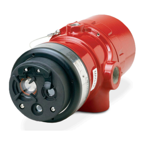
Select a mounting orientation where the Open Path
Eclipse status indication LED is visible to personnel
within the area.
Module Separation Distance
The transmitter and receiver modules must be installed
directly facing each other across the area to be protect-
ed. Physical obstructions in the direct line of sight
between the modules are not permitted. The overall line
of sight distance between the modules must not exceed
a maximum separation distance of 60 meters (198 feet).
The minimum module separation distance is 20 meters
(66 feet), unless special modifications are provided.
System Mounting Elevation
In all cases, the modules should be installed at the
same elevation above grade to ensure that alignment
capability and foul weather performance are not com-
promised. For detection of lighter than air vapors such
as methane, installation of modules at approximately 2
meters above grade minimizes typical beam block con-
ditions due to human activities, while enabling satisfac-
tory detection capability. For detection of heavier than
air vapors, installation of detectors below the expected
leakage source is generally recommended unless nui-
sance beam blocks will occur at an unacceptable rate.
In this case, identification and analysis of application
specific conditions should be completed to determine
the optimum installation elevation.
Sources of Heavy Contamination
Avoid locations where high levels of contaminants will
persistently be blown onto the detector windows.
Potential sources of heavy contamination include gener-
ator / turbine exhausts, flarestacks, drilling equipment,
process vents / chimneys, etc. If sources of heavy con-
tamination cannot be avoided, consider fitting extra
shielding and/or providing good access for routine
cleaning.
Snow and Ice in Ambients Below –20°C
The heated optics on both modules will melt snow or ice
on the windows in ambient temperatures down to
approximately –20°C. Below this temperature, snow or
ice blown onto the window will not be melted until the
ambient temperature rises. If longterm outdoor opera-
tion in very cold climates is intended, extra shielding /
covers are recommended to prevent accumulation of
snow and ice on the windows.
Deluge and Flooding
The modules are rated IP66 and will not be damaged by
occasional deluge or flooding. However, during such
an event, the unit will completely lose it’s IR signal and
will enter the “Beam-Block / Fault” state. In addition,
when the deluge / flooding subsides, there is the possi-
bility that contaminants will be left on the windows.
Install the modules away from areas particularly prone
to deluge or flooding.
Areas Prone to Subsidence and Settling
Avoid installation of the modules in areas where prob-
lems with subsidence, settling or thawing of permafrost
can occur or cause significant movement. If such loca-
tions cannot be avoided, the foundations of the mount-
ing structure should be engineered to minimize any
angular movements.
Areas Prone to Earthquakes
In the event of an earthquake, there is a chance that the
modules will become misaligned with respect to each
other. As long as the modules do not suffer from direct
mechanical impact damage during an earthquake, they
should remain undamaged by such events. After an
earthquake, it is recommended that the system align-
ment be checked. Antivibration mounts are unlikely to
be of any benefit and are not recommended.
Misalignment by Accidental Impact
Locations where there is a significant likelihood of
equipment, personnel or moving objects accidentally
knocking the modules out of alignment should be avoid-
ed where possible. If such locations cannot be avoid-
ed, measures including improved mechanical protec-
tion and warning notices should be considered.
895-85561.1
