Detech EDS GOLD CATCHER User manual

EDS GOLD CATCHER
28 kHz
VLF
ASSEMBLING YOUR DETECTOR
Your detector is equipped with an entirely new type telescopic shaft. It
consists of three parts: upper, middle and lower shaft. The lower shaft is made
of fiber glass enforced polymer. And the middle and upper shafts are of
alluminium alloy, which makes them extremely strong, and very light at the
same time. The shaft is designed in a way, that even very tall operators to be
conveniently working with it in its full length position, and in maximum shorten
position allows convenient operation even by children.
More data of the sizes you could find in the specifications chart.
The three parts of the handling are locked by two num-lock rings. These
are made of enforced polymer. They tighten very well the three parts of the
shaft and make the telescopic handling very stable while sweeping the coil.
The handle of the shaft is ergonomic, with continuously various regulation
of the distance to the arm-rest, very well fitting to the hand. The arm-rest is
padded with genuine leather and creates the sensation of pleasant touch, and
limits hand’s sweating. To the arm-rest there is an arm-rest strap for better
tightening the arm-rest to the operator’s hand.
The detector is extremely well balanced. It is easy for assembling and
disassembling. Convenient for operation, and in folded position very
convenient for transportation. In the next few steps we’ll explain you how to
assemble your detector in the easiest way.
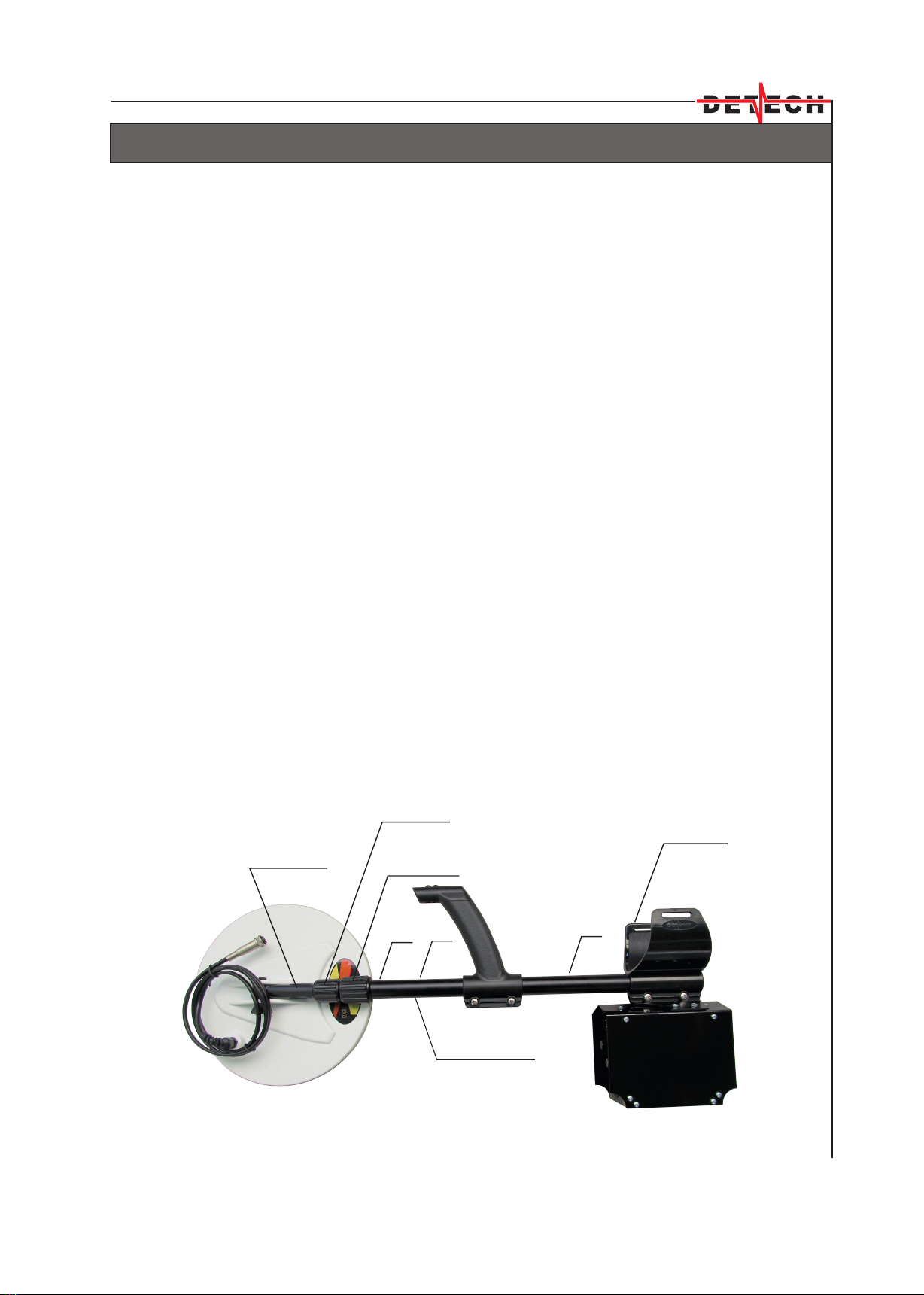
On Figure 1 the detector is folded - transport position.
1
Figure 1
Upper shaft num-lock ring
Upper shaft
1
2
3
Arm-rest
1, 2, 3 -upper shaft holes for length regulation
Lower shaft
Middle shaft num-lock ring

1. Unscrew the num-lock ring of the upper shaft and pull out the middle
shaft (it will move together with the lower shaft and the coil). Look for the
coincidence of the white lines of the upper and the middle shaft. We
recommend to pull out until the snap button clicks into the second adjustment
hole of the upper shaft. If the detector will be operated by a low height person
the snap button could click into the first adjustment hole of the upper shaft.
After you have chosen the length of the handling you could tighten the locking
ring of the upper shaft.
2. Unscrew the num-lock ring of the middle shaft. Pull out the lower shaft
and turn it until the coil is oriented in its operational position. If the coil is
oriented correctly, when pulling out the lower shaft its snap button will click
into one of the six holes of the middle shaft. After you choose the necessary
length tighten the num-lock ring of the middle shaft.
3. Check whether the cable is wrapped well around the shaft. Do not allow
the cable to flop loosely over the searchcoil. Since the detector is sensitive
enough to see the tiny wires in the cable, a floppy cable can cause false
signals, as the coil senses the moving wires. To secure the coil cable from
unwrapping you should fix it to the lower and upper end of the handling with
the two cable retainers.
4. When you have already set the operational length of the handling, adjust
the coil in working position toward the ground, and if necessary tighten by
hand the thumb nut on the mounting screw.
When you decide to assemble the detector in its transport position follow
the next steps:
1. Unscrew the num-lock ring of the middle shaft. Push the snap-button of
the lower shaft, turn the lower shaft slightly and slide it into the middle shaft.
Then tighten slightly the num-lock ring of the middle shaft.
2. Unscrew the num-lock ring of the upper shaft, push the snap-button to
sink, and slide the middle shaft (it will move together with the lower shaft and
the coil) into the upper shaft. Then slightly tighten the num-lock ring of the
upper shaft.
3. Now turn slightly the coil to lay on the folded shafts.
Your detector is standardly equipped with 6" and 10" round, closed design
DD coils. We have chosen such closed design coils for easier operation in
bushy and stony areas.
For first tests and acquaintance with the detector we would recommend
you use the 6" coil in field conditions, away from the electromagnetic
interferences of the built up areas. The bigger sized 10" coil is more sensitive
and deep, but to use it you should have some more experience with the
operation of the detector.
ASSEMBLING YOUR DETECTOR
2

ASSEMBLING YOUR DETECTOR
3
The length of the handling should be adjusted in a way
that the detector does not become tiring or
uncomfortable after long use. The detector grip should
rest in your hand with your arm relaxed, with the shaft
extending out in front of you. You should be able to
swing the detector back and forth in front of you,
using relaxed shoulder movement. The search coil
should not touch the ground during your sweep.
The angle of the search coil should allow its bottom
to be parallel to the ground, as shown on Figure 2.
Swing the detector from side to side in about three
foot arc, overlapping succeeding strokes well. The
detector is designed to get maximum depth without
the requirement for speed of sweeps, so go at a
pace that is comfortable for you. In fact, trying to
hunt too fast may even cause a loss of depth in heavily mineralized
locations. Regardless of which mode you are using, try to keep your search
coil height constant and at about an inch over the ground surface.
Most people tend to raise the coil at the end of
the sweeps, much like a pendulum, especially if
they are in a hurry (Figure 2)
Try to avoid this as any increase in the operational
height from the ground will cause a corresponding
loss of detection depth. This is easy in lawns,
where you just allow the coil to rest on the grass as
you sweep from side to side. In rough and rocky
areas it is not so easy.
Hitting the ground or rocks may cause false signals.
The sharp lowering, pressing the coil to the ground,
especially in wet and heavily mineralized grounds,
could also cause false signals.
Figure 2
Figure 3

AUTO MODE OF OPERATION
First we’ll introduce the easiest mode of operation of the detector. Further
in the instructions we’ll call it AUTO mode. The important thing for this mode is
that there would not be necessary to make manual ground adjustments to the
different ground conditions.
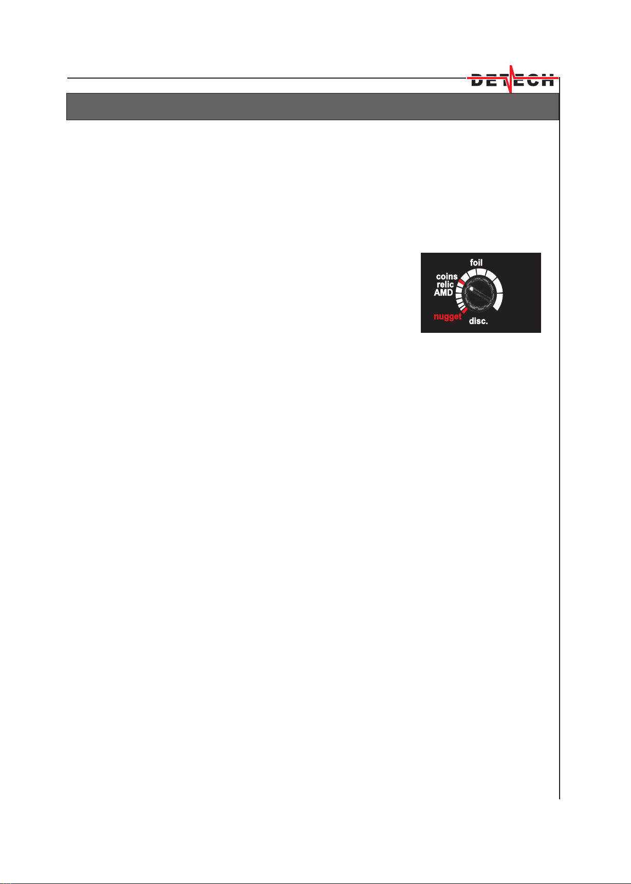
Turn all the controls and switches
to the red marked positions (Figure 4).
GND adjust and threshold (on the rear
panel of the control box) do not have
red markers, as they do not take part
in this mode of operation.
Freq.1/Freq.2 switch has no red
marker too. The frequency 1 or 2 is
chosen depending on which of these
two frequencies the detector is less
noisy. The choice is made with one
and the same sensitivity level.
When turning the detector on
(on/off button on the rear panel) it
congratulates you with alternating
green and red lights . Then for a
second the LED indicator will
light in green, if the batteries
are charged, and in red- if the
batteries are discharged and
need to be recharged.
The disc control has two red
zones. For nugget hunting is the most counterclockwise red zone. In this zone
you won’t have audio discrimination. For coin shooting use the coins zone. If
you want to dig the bigger sized ferrous targets like knives, arrows and spears,
rifles, guns, turn back this control to the relic position. In this position the
detector will reject only the tiny pieces of wire. Do not increase the
discrimination beyond the foil mark, the detector will start rejecting some thin
jewelry and low conductivity coins or other targets. More detailed description
of the functions of this control will be given in the instructions further on. After
you have got accustomed with the detector’s operation with these settings,
you could turn the low/high switch to the high position. This will make your
detector significantly more sensitive and deep. You could add more sensitivity
by further rotating clockwise the sens. control, until you hear rare interrupted
noises. The coil should be static while you change the sensitivity level, and the
interrupted noises will fade when you start sweeping the coil.
We recommend in this mode to use the one tone position(marked in red) of
the mixed/one tone switch.
Figure 4
4
M ground
A ground
freq.1
freq.2
all metal
high mixed
low one tone
disc.
AMD
relic
coins
nugget
foil
sens.

MANUAL MODE OF OPERATION
The AUTO mode of operation is the easiest one, but it does not give you
the best performance as sensitivity and depth of the detector. In the chapter
below we’ll introduce the Manual mode of operation. This mode
of operation is recommended for very experienced
detector operators. In this mode is always made
a manual ground balance.
Please, raise and hold your search coil about
10 inches off the ground and parallel to the ground
surface, as shown on Figure 5. You should be away
from metal objects. Then turn the switches
all metal/disc to all metal, A ground/M ground to
M ground (manual ground balance), see Figure 6.
The engagement of M ground and all metal positions
activates the GND adjust (ground adjust) and
threshold controls on the rear panel.
The disc. control becomes non-active, the detector
won’t have audio discrimination and will register with one and the same tone
all the metal targets, no matter the
rotation of the control in one or other
direction. Now turn on the detector
and set the sens. control to the red
marked position.
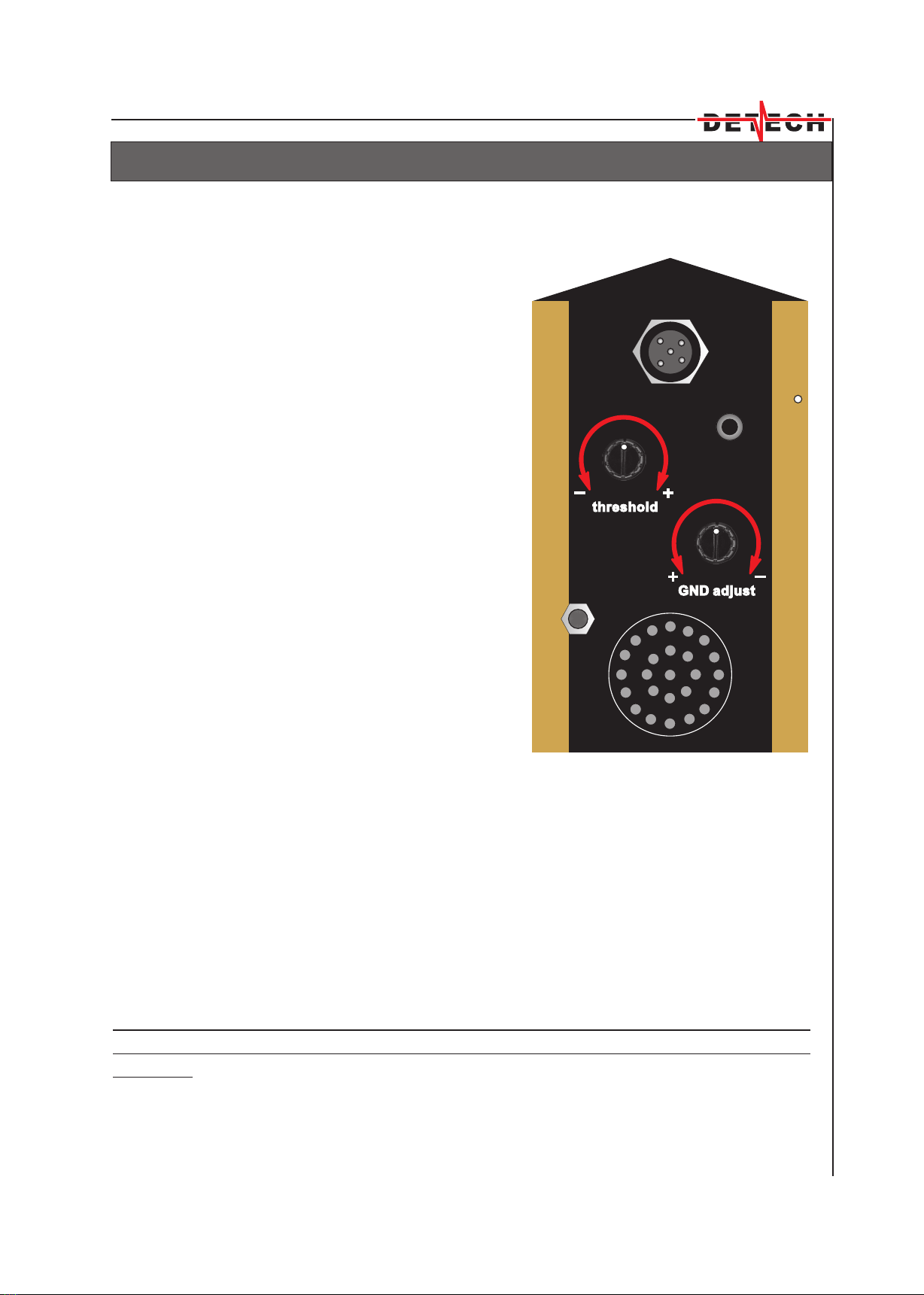
Then rotate the threshold
control until you start hearing a very
weak, faint hum.
Now slightly press the GND
adjust control until it “sinks”into the
panel. At the moment of pressing the
control you’ll hear a slight click, and
the indicator in the centrum of the
panel will light green. Then release
GND adjust control. The indicator
will turn off and you are ready for
manual adjustment of the ground
balance. Lower the coil to about
1 inch off the ground - the threshold
tone will get louder. Turn the GND
adjust control clockwise. Then pick
up the coil and push down again.
The threshold hum gets louder again.
and you’ll have to rotate the GND
adjust control further clockwise.
Figure 5
Figure 6
10"
6
M ground
A ground
freq.1
freq.2
all metal
high mixed
low one tone
disc.
AMD
relic
coins
nugget
foil
sens.

AUTO MODE OF OPERATION
5
IMPORTANT NOTE: When operating on very heavy and wet grounds,
especially if using the bigger sized coils (10" and 12.5") while passing the
coil over an open hole in the ground, even if there is no metal in it, is
possible to hear false signal, as if in the hole there was a metal target. In
such case switch the M/A ground to the M ground position and press the
GND adjust control to “sink” into the panel (the led indicator will light in
green). In most cases this will eliminate that negative affect and will result
in more stable operation of the detector, of course, slightly decreasing its
depth parameters. If the affect of the hole does not disappear, you should
assemble the smaller sized coil.
MANUAL MODE OF OPERATION
Continue with this, and on normal grounds at the 7th -8th clockwise turn
towards the “-” position of the GND adjust
control (Figure 7 - rear panel) the threshold
tone won’t change while lowering the coil
to the ground. At this point the detector is
balanced for the area and ready to hunt.
If you rotate the GND adjust control further
to the “-” position you’ll pass this point of
balance. Then the detector will get quiet
while lowering the coil to the grounds
surface, and it will increase the threshold
tone when raising the coil. This means that
you should return the GND adjust control
slightly to the “+” position until you get
a constant threshold hum while pumping
the coil. Lets note, that from the sinking into
the panel the clockwise rotating of the
GND adjust control in continuation of 20
turns there will be a change in the ground
balance. If you continue to rotate the knob
after these 20 turns you won’t get any more
change in the balance. If you are confused
for some reason, press again the GND
adjust control, this will return you to the
initial point, and you could start the procedure
again.
When you ground balance on very heavy grounds it is possible to have
cases when you hear increasing tone while lowering, and while raising your
coil. If this increased tone is with one and the same volume you have a correct
ground adjustment. This is a normal affect for the very heavy grounds. To
decrease or make this unpleasant affect disappear you could decrease the
sensitivity level of the detector or the threshold level. Then the detector will
become less sensitive and deep, but will operate normally regardless the
heavy ground.
Remember that the coil must be lifted straight off the ground. Swinging
the coil in an arc will cause false readings and will result in not proper ground
balance.
If the all metal/disc. control is in all metal, and the switch A ground/M
ground to A ground position the detector won’t operate correctly and won’t
allow you to make a correct ground balance adjustment.
We would recommend the use of this mode of operation for nugget hunting
and when smaller sized coils are assembled to the detector.
7
Figure 7
ON/OFF

MANUAL MODE OF OPERATION
The affect of the hole
When you operate the detector on heavy and wet soils conditions,
especially when you use bigger sized coil, while passing over an open hole
you’ll hear audio signal from the detector, even if in the hole there is no any
metal object. To avoid this unpleasant effect while sweeping the coil over the
hole rotate GND adjust knob counterclockwise, a turn or two, until this effect
disappears.
If you have made a good adjustment of the ground balance for a certain
ground, and it is rich of hot rocks, these hot rocks will give a quite specific
negative response. To overcome this problem take some of these hot rocks
and place them together at a clear of metals place. Sweep the coil at about 2
inches over the rocks and rotate GND adjust control 1-2 turns
counterclockwise, until the negative response disappears.
While operating on normal grounds some professional TH-ers to
increase the sensitivity and depth, especially for smaller targets, after finding
the exact ground balance point they rotate slightly clockwise the GND adjust
control until they receive an increase of the threshold volume when raising
the coil. This is a difficult way of operation, because it is possible to appear
false signals caused by the curved ground balance.
If during the operation you start hearing parasitic signals and feel that
your detector has lost its stability most probably the soils conditions have
changed significantly. You should ground balance the detector again for
these changed ground conditions.
In some specific ground conditions the ground balance point would not be
found. When this happens it is best to switch to the AUTO mode of operation.
The same you could do in any case when you meet difficulty with the ground
balance adjustment on some grounds.
You should know that the processor of the detector does not remember
the last adjustment of the ground balance which you had used. So that if you
have turned off the detector and turn it on again even on the same ground
you’ll have to make a new ground balance adjustment.
Ground balancing is a learned skill that you should practice often.
8
DISCRIMINATION
9
The disc control is enabled when you switch the all metal/disc. to the disc.
position .The fully counterclockwise position is marked in red - nugget. In this
position you won’t have any audio discrimination of metallic objects. You
should know, that in heavily mineralized ground tiny pieces of gold can
sometimes look like iron to the metal detector, and
small iron pieces can look like gold. So we
recommend this mode of operation for nugget
hunting.
The next zone is the AMD (all metal disc) zone. The
professional TH-ers use this mode of operation to
study the new sites they are working on.
The advantage of the AMD adjustment is that you
won’t miss any metal target in the ground. The bad
thing is that you’ll have to loose time for digging too
many unwanted ferrous targets like pieces of wire,
nails, etc.
The next zone of this control is relic. As we earlier mentioned in this position
the detector will eliminate only the tiny pieces of wire. All the bigger sized
targets will be accepted. Most professionals prefer working with this
adjustment of the disc. control, because the detector is really deep with such
a low discrimination level.
The next zone is coins. Here you’ll have good rejection of the ferrous
targets, and you’ll accept all the non-ferrous targets. We recommend this
position of the disc. control for searching areas littered with iron trash. If you
have too many pieces of foils rotate the disc. control after the foil zone. Have
in mind that the categorical foil rejection will bring to the rejection of some thin
golden jewelry.
If you decide to use even higher level of discrimination, for example the last
zone or the one before it you’ll reject the foil, more of the pull tabs, screw caps,
but you’ll loose some coins like the nickel 5 cents. The detector will keep its
good response to more of the coins, like 1 cent, dime, quarter. Even the lower
conductivity ancient coins like the Greek obols, diobols, the Roman asses,
follises, sestertii, the Byzantine follises will produce nice, smooth response. A
big part of the jewelry will be rejected, as well as the thin small gold coins. We
do not recommend such high levels of discrimination.
Even if you are with the highest discrimination level the big oxidized irons
will not be discriminated. Though they produce a clear response, the more
experienced detectorists manage to discern them and avoid their digging.
Figure 8
NUGGET HUNTING
10
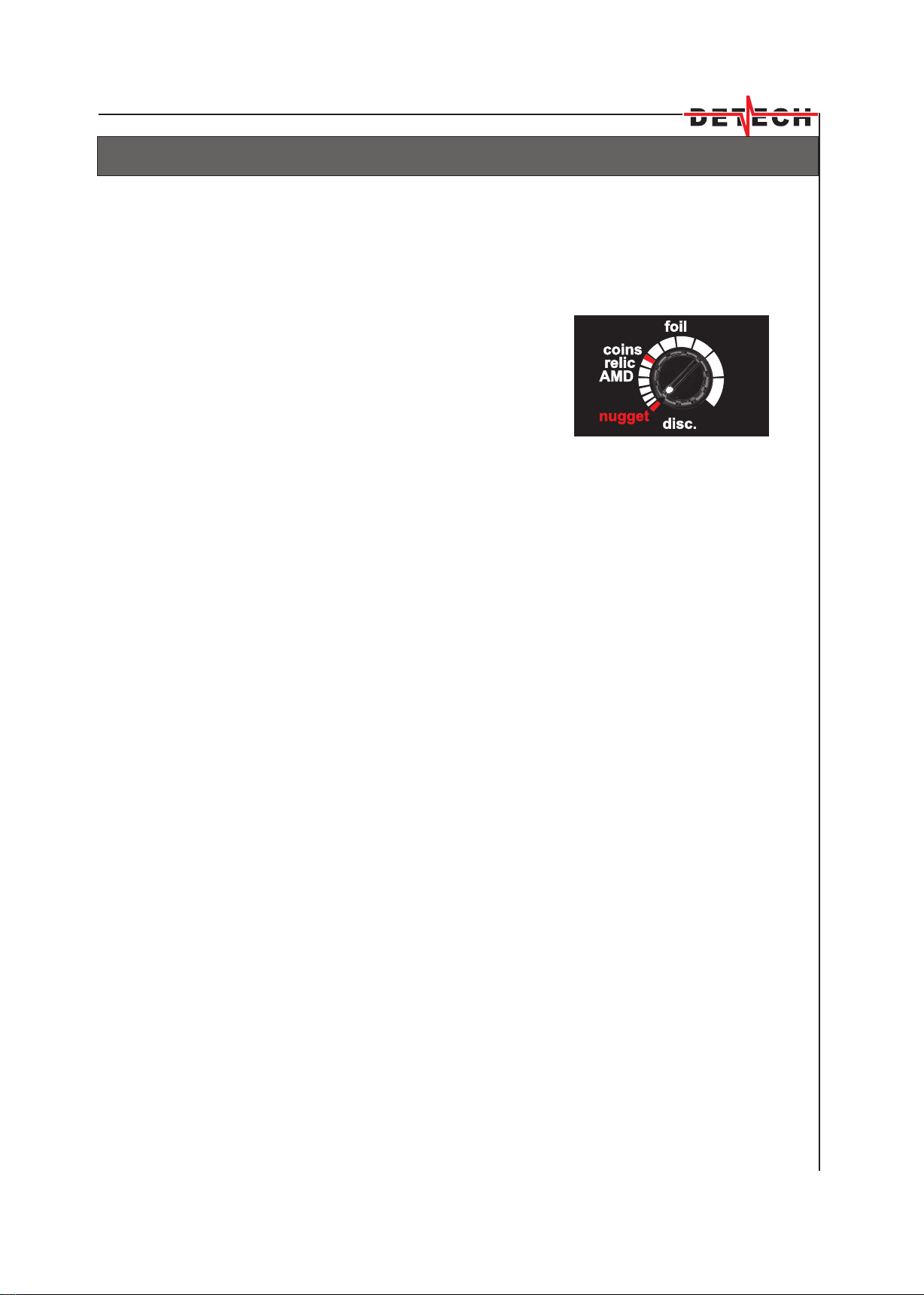
The easiest mode of operation for nugget hunting is the Auto mode (see the
AUTO MODE of operation chapter). Have in mind that the disc. control should
be in the nugget red zone(Figure 9).
In this position, as in the AMD zone you won’t
have audio discrimination of the metallic objects
in the ground. Lets remind you again that in
heavily mineralized grounds the tiny pieces of
gold can sometimes look like iron to the metal
detector, and small iron pieces can look like gold,
so we recommend this mode of operation for
nugget hunting. The advantage is that you won’t
miss any metal target in the ground. Move the
coil just over the grounds surface and with a
mean speed of movement. Probably you’ll need
time to determine the proper search speed and technique. Do not go too fast.
Try to overlap your sweep paths so that you won’t miss the small and deeper
metal targets.
For maximum sensitivity and deeper searching with the detector we
would recommend to turn the detector to MANUAL MODE of operation. This
mode of operation will require more patience and very good knowledge of
your detector’s operation and control. It is designed to find gold nuggets,
however it is very useful for relic hunting, and the detector will also respond to
all metal alloys including common coins.
Figure 9

BEACH HUNTING
11
For beach hunting we recommend the operation of the detector in its
AUTO mode of operation. Lets start with the beach hunting on normal dry
beaches.
These beaches are the easiest for searching, and allow the highest
increase of sensitivity level, even switching to high of the high/low switch. Of
course, if there are no strong electromagnetic fields nearby. On the beaches
the most valuable finds are the golden rings, golden earrings, golden chains.
May be you know, but the thin golden jewelry is low conductivity, so not to miss
them we recommend the position of the disc. control between relic and
coins. If you go further clockwise, beyond coins, the detector will start
rejecting the tiniest golden chains. If you want to ignore the thin jewelry, and
emphasize on coin shooting and search of higher conductivity jewelry you
could increase the disc. control level, so that you start rejecting the most of
the foils. This will save you the scooping of unnecessary trash, but you’ll loose
the thin golden jewelry.
Searching on salt wet sand beaches. In such conditions to have a
smooth operation of the detector, with no false signals, first turn the high/low
switch to low. Then do not choose too high levels of the sens. control. And the
most important - while sweeping over the wet sand rotate the disc. control
clockwise until the parasitic signals, caused by the conductivity of the wet
sand, disappear. This rejection of the parasitic signals will be active after the
coins zone. To keep a good sensitivity to the targets in the wet sand it is very
important to stop rotating the disc. control exactly at the point where the
parasitic signals are rejected. If you pass this point you won’t hear any more
parasitic signals, but will reject some good targets.
Searching on black sands. These sands contain high percentage of
magnetic negative iron oxides. In such conditions many of the low
conductivity non-ferrous targets will look like ferrous for the detectors. That is
why we recommend you for black sand hunting to decrease the disc. control
level. Remember that it is best to search in the AUTO mode of operation. It is
advisable also to switch to low the high/low switch, and not to increase too
much the sensitivity level. Do not worry about the decrease of the level of
discrimination - on the beaches the ferrous targets are rarely met.

CONTROLS
12
Figure 9
The sens control is often thought of as a depth control and it is, but it can
also be used to make the detector more stable if interference caused by
ground mineralization or electrical fields are experienced. The sens control
works in conjunction with the adjustments of the high/low switch. The low
position of that switch is for maximum stable operation, while the high position
is for maximum sensitivity and detection depth.
For mass searching we recommend to use the low
position of the switch. The beginners could use it and
increase the sensitivity level to the boundary where the
detector remains quiet and stable. For the very experienced
TH-ers we would recommend the position high of the switch.
For maximum depth and sensitivity the professionals should
then rotate sens control clockwise until they hear rare,
interrupted tones from the speaker. When they start sweeping
the coil these tones will be oppressed by the ground, and the
operator will hear only the useful responses from targets in the ground.
Of course, all this is valid if the detector is operated in its Discrimination Mode.
The switching to high should be made if the ground and atmosphere
interferences are normal. If the grounds are heavily mineralized, or if there are
too many electromagnetic disturbances, the low position of the same switch
should be used.
When testing the detector in built-up places, where there are many
electromagnetic interferences, you won’t be able to increase too much the
sensitivity level. That is why for the tests of the real parameters and qualities of
the detector we would recommend the field testing. If the detector is slightly
noisy, before decreasing the sens. level try with a change of the operation
frequency (from freq.1 to freq.2 or vice versa) and check whether the detector
has become less noisy.
The normal position of the freq.1/freq.2 switch is the freq.1,
and it is for 28.024 kHz operating frequency. If there are
interferences received you could choose the frequency, where
the detector is less noisy. The frequency switch positions are
designed to eliminate the radio-frequency interferences mainly
in competition hunting or when searching in close proximity to
another detector with a similar operating frequency. If there is
an other detector with the same frequency, to operate both
detectors normally they should be operated on different frequencies.
Figure 10
CONTROLS
13
Figure11
The detector has two sound modes - one tone and mixed. When the relevant
switch is on its one tone position, when the detector registers a target, no
matter its conductivity, you’ll hear it with one and the same tone. When the
switch is on its mixed position, the detector separates the metals by sound-
ferrous - which will be registered with a low pitched tone, and non-ferrous-
which will be registered with higher pitched tone.
To have such a tone identification of the targets the
disc control should be in its nugget position (the disc
control turned fully counterclockwise). If you place the
disc control in coins position the detector will reject the
ferrous targets and you won’t hear them. All the
non-ferrous targets will be registered with the higher
pitch tone.
We recommend the operator start his training using the
one tone position of the switch.
The experienced hunters use the mixed mode when they study a certain
unknown terrain. In this way they “hear” the ferrous targets too, receiving
better information about the degree of pollution of the area with ferrous junk.
Please, have in mind that on heavy grounds the small deep nuggets will be
registered by all detectors as ferrous targets. If in such a case you use a mixed
mode of tone identification, the detector will register these small deep nuggets
as ferrous targets, i.e. with a low pitch tone. Or the detector will hesitate
between low pitch and high pitch tone.

FALSE SIGNALS AND SOLUTIONS
14
A false signal occurs when something sounds like a good target, but it is not.
These signals are produced by undesirable or discriminated targets like large
pieces of iron, hot rocks or by electrical pulse-type electromagnetic
interference. Your detector has a very good discrimination, but some bad
“targets” with similar electrical characteristics could fool it. Some items very
close to the search-coil could sound good, as well as large pieces of trash. The
experience is the best teacher. With more practice with your detector you’ll
soon learn how to distinguish the false signals. At first, when you get a good
response you’ll find that crossing over the target once or twice more the signal
would break up or completely disappear.
The sources of false signals could be:
- Electrical interference, caused by high voltage power lines, TV and radio
towers, electricity transformers, cells of mobile phone operators or other
detectors. Move farther away from the source, lower the sensitivity level.
Switch the high/low switch to the low position. The use of a smaller sized coil
is also a good solution.
- Highly mineralized soils (with high iron or salt content). In such
conditions reduce the sensitivity, increase the level of discrimination. If
searching in the all metal mode and with M ground position of the M
ground/A ground switch update the ground balance setting. The smaller
coils are possible solution.
- Extremely trashy areas may cause a lot of “chatter”. Increase the
discrimination level or reduce the sensitivity, switch the high/low switch to the
low position. In some trashy areas the smaller sized coil would be beneficial
for target separation.
- Metal Interference. The detector picks up metals above and on the side of
the search-coil, as well as beneath it. Be careful for your digging tool, metals in
shoes, and your coil cable hanging loose above the coil. Pay attention to be
away from railings, ferro-concrete poles, etc.

SEARCHCOILS
15
Your detector is equipped with 6" and 10"DD closed design searchcoils.
They have very good ground balance, stable operation, excellent depth of
penetration, very good pinpointing, accurate target identification, excellent
sensitivity, high temperature stability. The closed design allows easy sweeps
close over the ground.
The 10" is an universal size of searchcoil. This coil has good sensitivity - to
small and to bigger sized targets. It is good for search of jewelry, coins, and
relic hunting. It is designed for best all-arround performance, in all types of
detecting.
The smaller 6"DD coil gives better target separation, i.e. more distinct
target response for metal objects buried closely together, which is very useful
when hunting trashy areas. And it is the best coil for nugget hunting, especially
for the search of the very small, tiny nuggets.
The accessory 12.5"DD searchcoil is recommended for TH-ers who have
already accumulated experience in operating the detector. Its advantages are
the better sensitivity and depth, especially for the bigger sized targets, and the
greater ground coverage. As disadvantages could be given its more nervous
operation in mineralized and trashy grounds, slightly erratic operation on salty
wet sands. As every bigger sized coil it groups targets situated closely
together.
No one search coil is better than all the rest. Selecting the right searchcoil
depends on the factors such as what are you searching for and search site
conditions.
All the search coils are light for their sizes, very well electrostatic shielded,
resistant to shocks and shakes, perfectly balanced and waterproof.
They are all compatible and interchangeable, easy to mount and require no
special tools.
Coil covers
Your searchcoils come standardly with coil covers. They are very useful to
protect your searchcoil at any time, and we would warmly recommend their
constant use.

BATTERIES
16
Your detector is standardly powered by 6 Ni-MH batteries, size AA
(R6),1800 mAh, which allow you to use the detector for 20-30 hours. The time
of use depends on how many signals your detector will locate and process
and whether you use headphones. The use of headphones will increase the
time of battery use.
As we have already mentioned, when turning the detector on the led
indicator will light in alternating green and red lights for a while, and then for a
second with green light, if your batteries are charged. If this light is red, you
should take out and recharge (if the batteries are Ni-MH) or replace (if the
batteries are alkaline) the batteries.
If in the process of operation of the detector the batteries are discharged
on every 20 seconds the low battery indicator will blink in red, and you’ll hear
warning audio signal. If you do not turn off the detector, this will continue until
the batteries are fully discharged (not too long time), which is not desirable,
because is extremely harmful for the batteries themselves.
To remove the batteries, make the following:
Remove the lid of the battery compartment on the bottom of the control
box. You’ll see the batteries. In the bottom of the compartment are described
schematically 6 batteries and the direction of their location.
If the batteries are rechargeable, put them into the charger, of course,
keeping in mind the direction of their position in the charger. For a full charge
of your 1800 mAh batteries you’ll need about 15 hours. After the batteries are
recharged, or if you are going to use new alkaline batteries, put them into the
battery compartment, making certain to match the battery polarity with the
markings indicated on the bottom of the compartment..
WARNING: Be very careful to install correctly the batteries in the battery
compartment.

SPECIFICATIONS
17
Operating Frequency ................. Freq.1 - 28.024 kHz; Freq.2 - 27.910 kHz
Audio Frequency ...................................................... simple tone - 570 Hz
low pitch tone - 250 Hz
high pitch tone - 1100 Hz
Weight (with batteries included)....................................................... 1600 g
Length (extended) ................................................................. 57"(1450 mm)
(unextended).............................................................. 29" (740 mm)
Standard Searchcoils .............................6"DD, 10"DD round closed design
Optional Searchcoils: ......................................12.5" (320mm)closed design
SEF Pro ..........8" X 6"(203mm X 152mm)
9" X 9"(229mm x 229mm)
12" X 12"(305mm X 305mm)
Headphones ................................Impedance ......................... 8 - 32 Ohms
Mono / Stereo Jack .......................... 1/4"(6.3mm)
Optional ......................................................................... wireless
Batteries ....................... Standard ............................ 6 Ni-MH , 1800 mAh
Ni-MH battery Life .................................................................. 20 - 30 hours
Low Battery Alert ................................................ Automatic LED and Audio
Ground Rejection .............................................................................. AUTO
Manual Ground Adjust
Search Modes .......................................................Adjustable Discrimination
All Metals/Ground Adjust Enable
Target identification by dual tone (high/low pitch tone)
Controls .................................................sens., disc., GND adjust, threshold
Switches ................................... high/low, freq.1/freq.2, M ground/A ground,
all metal/disc., one tone/mixed
Warranty ............................ Control Box ....................................... 2 years
Searchcoils ......................................... 2 years
Patents ..................................................................................... BG 817 Y4

MAINTENANCE
18
Your detector is a high quality electronic instrument. Though ruggedly
constructed and designed to withstand the normal treasure hunting demands
proper care is essential.
Operate your detector as recommended in this instruction manual.
Remove the batteries from the detector if you are not going to use it for
extended period of time. This will prevent the detector from batteries leakage
and damage.
Sweep the searchcoil carefully and avoid hitting it against rocks, trees
and other hard surfaces.
The use of coil cover is highly recommended to protect the searchcoil
from abrasion.
The searchcoil is waterproof, but the electronics are not. Always prevent
any moisture or water from entering the control box of the detector.
Protect your detector from dust, moisture, and extreme temperatures.
Keep it clean and dry and avoid getting sand and grit into the shafts or the
tightening nuts.
Do not use solvents to clean the detector.
Keep the coil cable properly wound around the shaft and protect it.
Floppy, pinched cable may short, causing erratic noises or unnecessary
replacement of the searchcoil.
Do not attempt to modify or repair the detector’s electronics as this will
void your detector’s warranty.
Table of contents
Other Detech Metal Detector manuals


Popular Metal Detector manuals by other brands


Fisher Research Labs
Fisher Research Labs CZ-3D operating manual

Fisher Research Labs
Fisher Research Labs iMpulse AQ Limited owner's manual

OKM
OKM Fusion user manual

Minelab
Minelab GPX 6000 quick start

Teknetics
Teknetics Eurotek Pro 11DD owner's manual

Fisher Research Labs
Fisher Research Labs 1280-X Aquanaut operating manual