Develop ineo 958 User manual

E-12016. 3 Printed in China
©DEVELOP GmbH
/
INSTALLATION MANUAL
A795-9625-00
Applied Machines: /
<Important>
Be sure to correctly follow the procedures in order as explained in this Installation Manual.
If you do not follow the procedure in order, the image trouble may occur.
1. Outline of installation procedures
When installing the machine and associated options as a system, follow the order shown on the upper.
Caution:
• When transporting the machine, assign an adequate number of persons to the job and follow the speci-
fied correct procedures.(mass: approx. 200 kg (440-15/16 lb))
Note:
• For the detailed installation procedures for each option, follow the instructions given in the corresponding
installation manual and perform the procedures correctly.
• Once the Power Switch is turned ON, do not turn OFF it until the installation work has been completed.
AU-201S
AU-102
WT-506
MK-735
WT-513
SP-501
OT-508 RU-515
PK-520
MK-715
KP-101
KH-102
HT-508*2
UK-501
LU-205
LU-303
FS-537FS-536 FS-537SDFS-536SD
FK-516*1
UK-212*1
SC-508*1
HD-524*1
EK-610*1
EK-611*1
Electronic system options
Machine
JS-602PI-507
PK-523
ZU-609
*1: No particular order in installation
procedures
*2: Varies depending on the applicable
marketing area

E-2
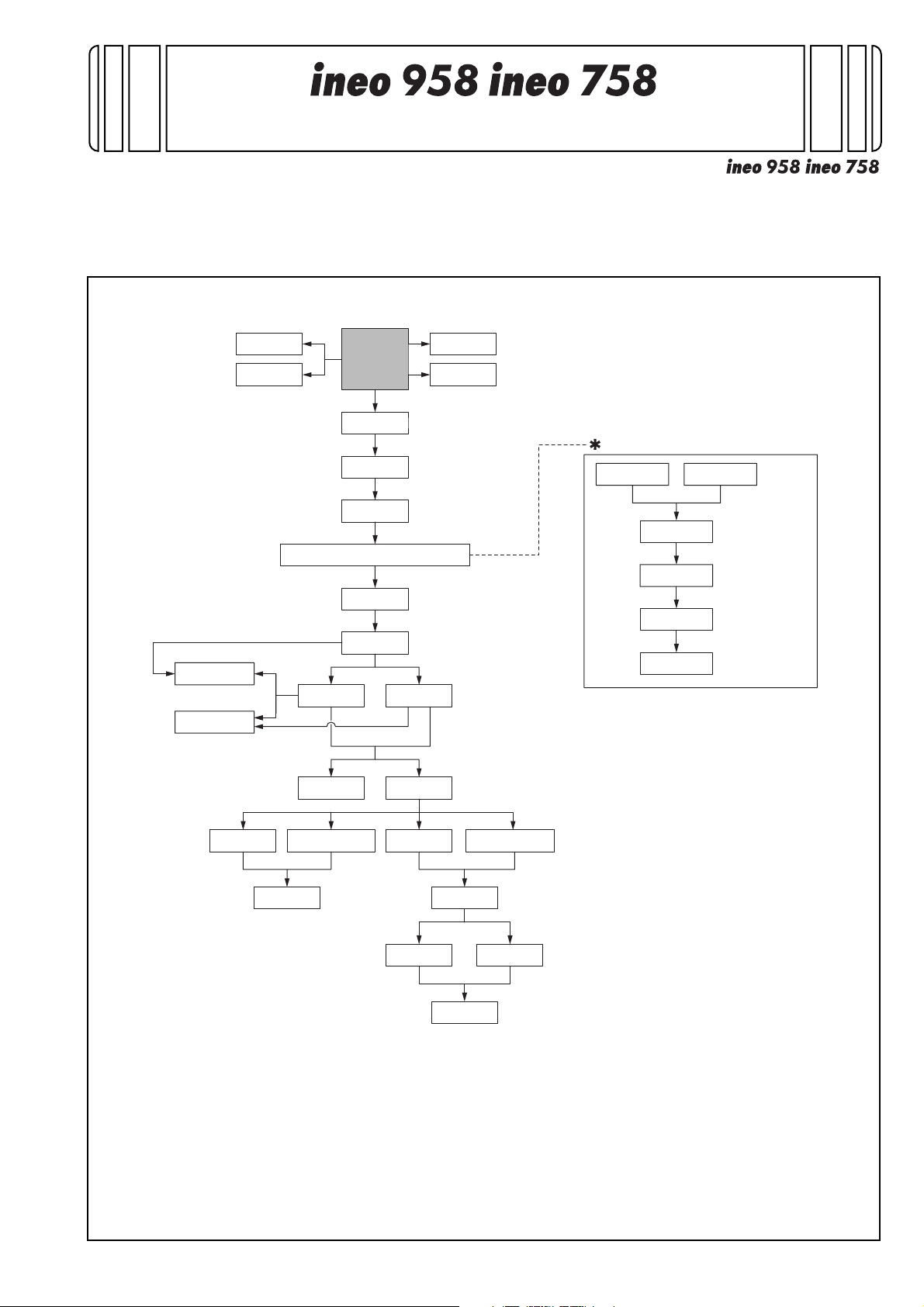
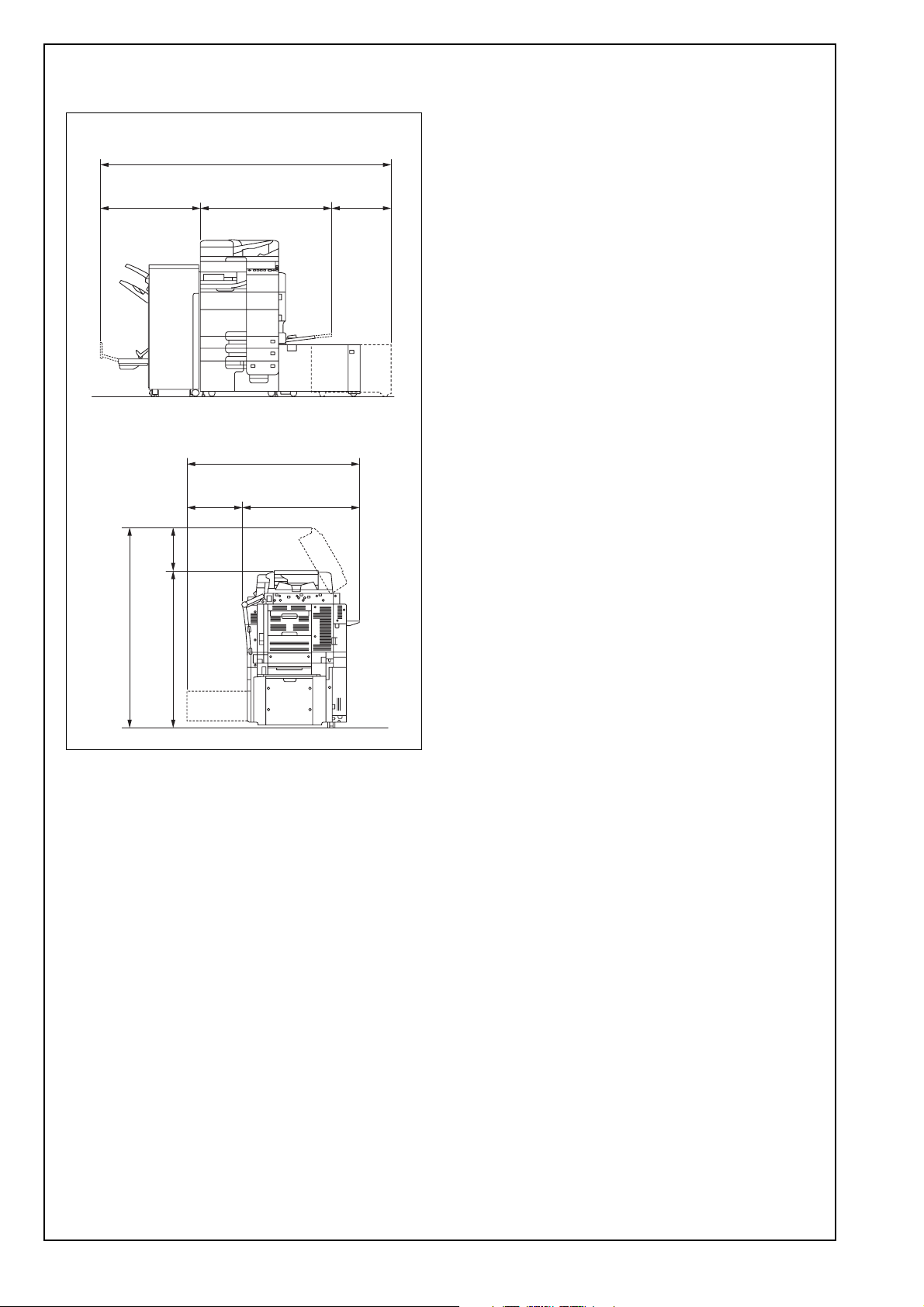
2. Installation space (unit: mm (inch))
ineo 958 + FS-537SD + LU-205
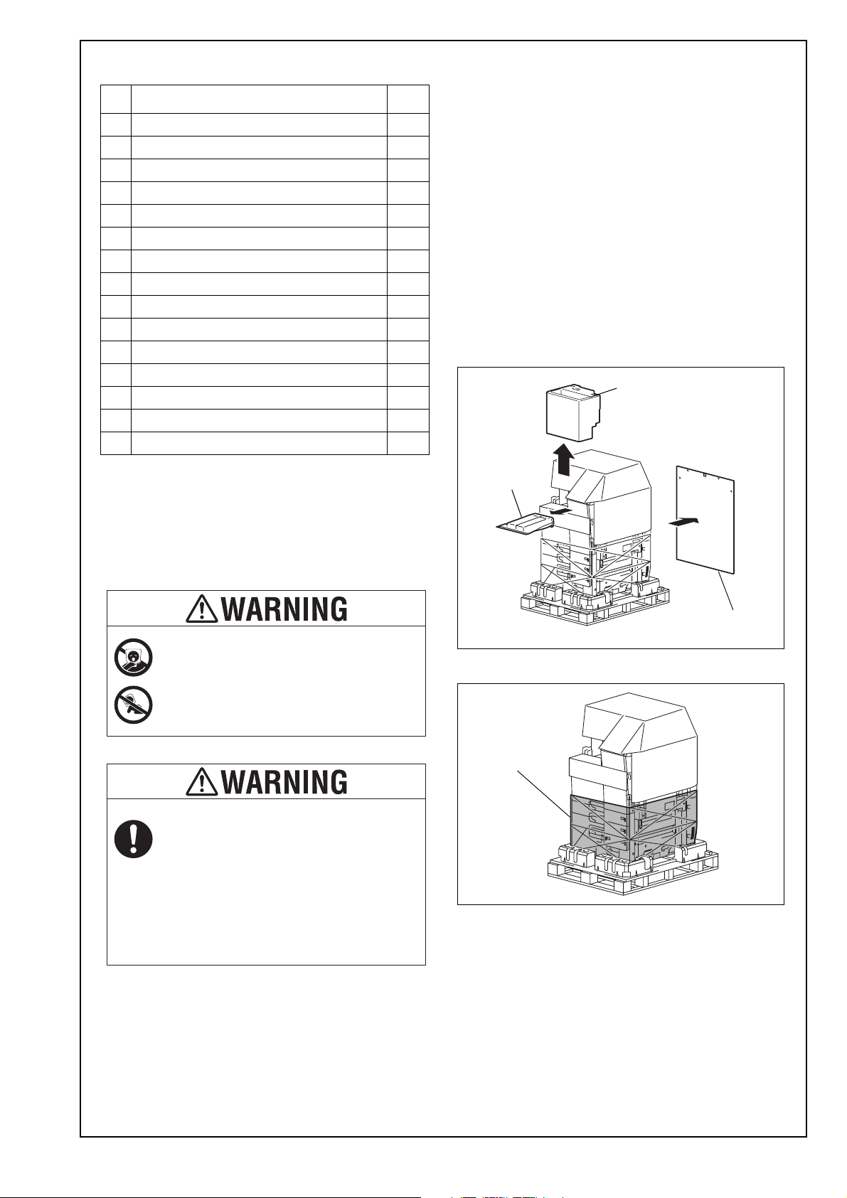
3. Pre-installation check items
(1) Select a level and stable place for installing the
machine.
(2) Be sure to use a power source of the voltage and
frequency indicated in the product specifications.
Ensure that the current carrying capacity of the
power outlet is at least equal to the current listed
in the product specifications.
(3) Power the machine directly from a dedicated
power outlet. (Do not use an extension cord.)
(4) Do not plug or unplug the power cord with wet or
dirty hands, otherwise you may get an electric
shock.
(5) Avoid a hot and humid environment, or a place
exposed to direct sunlight.
(6) Avoid a dusty location, or a place near volatile
and flammable substances.
(7) Avoid a poorly ventilated place.
4. Notes on using touch panel
Be sure to instruct users on the following points.
• This machine uses a capacitive touch panel.
When you touch the touch panel, use your fin-
ger or the stylus pen supplied with the machine.
If you touch the panel using your nail or a pen
tip instead of using your finger or the stylus pen,
the touch panel does not respond normally.
• Pressing the touch panel hard may cause dam-
age.
• Do not strongly press the panel or press it using
the sharp tip of mechanical pencils.
• The key is a finger tapping (quick light touch
using a finger) operation.
498
(19-5/8)
921
(36-1/4)
1232
(48-1/2)
353.5
(13-15/16)
1010
(39-3/4)
1419 (55-7/8)
1585.5 (62-7/16)
500
(19-11/16)
782
(30-13/16)
2292 (90-1/4)

E-3
5. Accessory parts
* Varies depending on the applicable marketing
area
Note:
Keep the tray label/paper size label at hand. It is
necessary for mounting the Large capacity unit
LU-303.
* Power supply: 220-240V 10A
Note:
This manual provides the illustrations of the acces-
sory parts and machine that may be slightly differ-
ent in shape from yours. In that case, instead of
the illustrations, use the appearance of your
machine to follow the installation procedure. This
does not cause any significant change or problem
with the procedure.
6. Unpacking the machine
(1) Open the shipping box and remove the packag-
ing materials.
Note:
• Keep the supplied slope and cushion A that are
removed in this step for later use.
• The cushion B contains accessory parts.
(2) Remove the stretch film from the machine.
No. Name Q’ty
1. User’s guide holder 1
2. Quick start guide* 1
3. Installation manual 1 set
4. User’s guide CD* 1
5. CD-ROM* 1 set
6. Tray label/Paper size label 1 set
7. Panel sheet* 1
8. Chart 1
9. Cap A (black) 2
10. Cap B (white) 1
11. Connector cover 1
12. Scanner cover 1
13. Mounting screw (3 x 8 mm) 1
14. Spacer 1
15. Stylus pen 1
Keep this bag away from babies and
children. Do not use in cribs, beds,
carriages, or playpens.
The thin film may cling to nose and
mouth and prevent breathing. This bag is
not a toy.
If a power cord is not supplied, use only
the power cord that meets the following
conditions.
Failure to do this could result in a fire or
electrical shock.
• The power cord has voltage and current rating
appropriate for the rating plate on this machine.
• The power cord meets regulatory requirements
for the area.
• The power cord is provided with grounding
pin/terminal.
Supplied slope
Cushion B
Cushion A
Stretch film

E-4
(3) Hold onto the handle of the machine and tilt the
machine to the right and left. Under this condi-
tion, remove the fixing materials.
(4) Separate the cushion into two and install them to
the pallet (at two places).
(5) Take out the slope and protective tape and
remove nails from the plastic bag.
(6) Position the slope as illustrated and drive nails in
to fix the slope in position.
Caution:
Insert the nails in the outer holes.
(7) Holding onto the front cover and the back panel
of the machine, slide the machine down along
the slope.
Caution:
Machine mass: 200 kg (440-15/16 lb)
• Perform this step on a level, stable site and
assign an adequate number of persons.
• When sliding the machine down, do not hold
onto the scanner portion.
• Do not insert your leg under the slope.
Nail
Nail

E-5
7. Removing protective tape, packing and
other shipping materials
(1) Remove the protective tape and protective mate-
rials.
Note:
Be sure to lock the lever after removing the protec-
tive tape A, B.
(2) Remove the reinforcement plate. (Four screws)
(3) Remove the locking screws.
Note:
Keep the locking material. It is necessary for trans-
porting the machine.
(4) Attach the supplied caps A and B.
A
B

E-6
(5) Install the supplied scanner cover. (One supplied
mounting screw)
(6) Remove the protective sheet from the control
panel.
(7) Pull the tray 1 out and remove the protective
tape from the tray.
Note:
See the User's Guide CD for instructions on set-
ting paper in each tray and configuring the paper
types.
(8) Pull the tray 2 out and remove the protective
tape from the tray.
(9) Pull trays 3 and 4 out and remove the desic-
cants.
(10) Remove the protective tape from trays 3 and 4.

E-7
(11) Open the lower front door and remove the
waste toner box.
(12) Remove the locking material. (One screw)
Note:
Keep the locking material. It is necessary for trans-
porting the machine.
(13) Install the waste toner box and close the lower
front door.
8. Installing the toner cartridge
Note:
Since no toner cartridge is supplied with the
machine, purchase a toner cartridge separately.
(1) Shake the toner cartridge up and down five to
ten times.
Note:
Shake the cartridge adequately. Otherwise, it may
cause trouble.
(2) Remove protective tape of the toner cartridge.
(3) Open the upper front door and insert the toner
cartridge into the machine.

E-8
(4) Push the toner cartridge all the way in.
Note:
Make sure that the toner cartridge is pushed all the
way in.
(5) Close the upper front door.
9. Installing other options
To install other options, refer to the installation man-
ual for each option and follow the “Installation Proce-
dures.”
10. Mounting the accessory parts
1. Attach the supplied connector cover.
(2) Remove the protective cover from the supplied
stylus pen.
Note:
Discard the removed protective cover.
(3) Set the stylus pen in the place shown in the illus-
tration.

E-9
11. Connecting the power cord
(1) Connect the power cord.
(2) Plug the power cord into the power outlet.
(3) To remove moisture from the paper in the tray,
turn ON the switch shown in the illustration.
Note:
This step may not be performed depending on the
applicable marketing area.
12. Starting the machine
Open the lower front door and turn ON the power
switch, then close the lower front door.
13. Date & Time Setting/Time Zone Setting
(Service Mode)
(1) Display the Service Mode screen.
(For details of how to display the Service Mode
screen, see the service manual.)
(2) Display the Date & Time Setting/Time Zone Set-
ting screen.
(To display the Date & Time Setting/Time Zone
Setting screen, press Stop →3 on the control
panel.)
(3) Do not input date and time but touch “Entry” of
the Date & Time Setting.
(4) Input the time zone using up/down keys or direct
keys.
(5) Touch “Entry” of the Time Zone Setting.
(6) Touch “Apply.”
(7) Touch “OK.”
(8) Touch “Next.”
14. Serial number input
Note:
Serial number input is, if necessary, needed only
for the optional devices installed in “9. Installing
other options.”
(1) Touch the item you want to enter and input the
serial number.
(2) Touch “END.”
(3) For other devices, enter their serial number in
the same way.
(4) Touch “END.”
(5) Touch “Next.”
15. Unit change
Note:
This function allows the user to select the type of
message that will appear when the replacement
time arrives for each of the different units.
(1) Select the appropriate message type for each
unit.
(2) Touch “Service.”
Use the appropriate power cord.
Failure to do this could result in a fire or
electrical shock.
Switch

E-10
16. Performing Non-Image Area Erase
Check
Note:
Perform the below at the site where customer
uses the machine.
(1) Select the Non-Image Area Erase Check func-
tion as follows:
Machine →Non-Image Area Erase Check.
(2) Open the reverse automatic document feeder to
the angle shown in the illustration.
Note:
• Do not open the reverse automatic document
feeder to 90 degrees.
• Do NOT place a document on the document
glass.
• Clean the document glass if dirty.
(3) Press the Start key.
(4) Make sure that “Result” is “OK.”
Note:
If “Result” is “NG1” or “NG2”, review the place and
direction of installation, or take measures to block
the light source (by covering it, etc.), then perform
installation checking again.
(If a fluorescent light or other bright light sources
exist right above the machine, the light source can
hinder installation checking and cause operation
errors in the Non-Image Area Erase Check. For
detailed information, see the service manual.)
(5) Touch “OK.”
17. Changing paper size (Tray 3 and 4)
Note:
Perform this procedure only when changing the
default paper size (Inch area: Letter, Metric area:
A4) is required.
(1) Pull out the tray 3.
(2)
<Changing the paper size in the inch area>
Remove the end guide plate. (Two screws)
<Changing the paper size to Letter in the metric
area>
Remove the end guide plates (front and rear).
(Two screws each)

E-11
<Changing the paper size to sizes other than Letter
in the metric area>
Remove the end guide plate (front).
(Two screws)
(3) Remove the front and rear paper guide plates.
(Four screws each)
(4) Align the paper guide plate (rear) with the line
marked in the bottom of the tray. Secure the
paper guide plate. (Four screws)
Note:
Depending on paper size, the positioning method
of the paper guide plate (rear) is different.
< B5/8.5”/16K >
Insert the paper guide plate (rear) into the hole
and press it towards the rear end of the hole until it
stops. Secure the plate with screws.
< A5/POST >
Insert the paper guide plate (rear) into the hole
and press it towards the front end of the hole until
it stops. Secure the plate with screws.
(5) Place a sheet of paper as large as the paper size
you are setting in the bottom of the tray. Align the
paper guide plate (front) with the end of the
sheet.
Gap between the sheet and the paper guide
plate (front): 1 mm or less
(6) Tighten the two front screws. Remove the sheet
and tighten the two rear screws.
(7) Align the end guide plate with the line marked in
the bottom of the tray and secure it.
(Two screws)
Note:
This procedure is not necessary when changing
the paper size to Letter.
Front Rear

E-12
(8)
<Changing the paper size to Letter in the metric
area>
Install the end guide plates (front and rear) at the
locations shown in the illustration.
(Two screws each)
(9) Close the tray 3.
(10) Select the LCC size setting function as follows:
System 2 →LCT (Build-in) Size Settings.
(11) Touch “Tray 3” and select the paper size that
was set for the tray 3.
(12) Touch “END.”
(13) Perform the same procedure for the tray 4.
18. Configuring other options
(1) If any of the following options are installed, refer
to the “Configuration procedures” of the installa-
tion manual for each option and configure the
option(s).
• Stamp Unit SP-501
• Double feed detection Kit UK-501
• Punch Kit PK-523/PK-520
• Z Folding Unit ZU-609
• Large Capacity Unit LU-205/LU-303
•FaxKitFK-516
• Local Interface Kit EK-611
• Security Kit SC-508
• Authentication Unit AU-201S/AU-102
• Upgrade Kit UK-212
• Hard Disk HD-524
• Working Table WT-513
•NetworkFax
(2) Exit from the Service Mode and return to the ini-
tial screen.
19. Connecting the network cable
(1) Connect the main body and networking equip-
ment (HUB) using the network cable.
Note:
The following shows the recommended network
cables that correspond to each communication
speed.
• 10BaseT/100BaseTX: Category 5
• 1000BaseT: Category 5E, Category 6
2. Check LEDs for lighting conditions.
LED1:
Should light up steadily if the link network con-
nection has been made.
LED2:
Should blink according to the communications
status of the ACT network.
LED1
LED2
Networkport

E-13
20. Network setting
Make the TCP/IP address setting for the network.
Note:
Consult the network administrator for the setting
value to be entered and make settings as
required.
(1) Select the function to be used as follows:
Menu →Utility →Administrator Settings →Enter
the Administrator Password →Network Settings
→TCP/IP Settings →IPv4 Settings.
(2) Touch “Manual Input” of IP Application Method
and make the following settings.
IP Address: IP address of the controller
Subnet Mask: Subnet mask of the network, to
which the machine is connected
Default Gateway: IP address of the default gate-
way
(3) Touch “OK.”
(4) Touch “OK” after the “TCP/IP Settings” screen is
displayed.
(5) Select the function to be used as follows:
Forward →Forward → Detail Settings →PING
Confirmation, and make the operation check of
TCP/IP.
21. Restarting the machine
(1) Open the lower front door and turn OFF the
power switch.
(2) Turn ON the power switch again after 10 or more
seconds have passed, then close the lower front
door.
22. Adjusting the height
(1) Check the clearance between the upper face of
scanner and the protrusion on the reverse auto-
matic document feeder side (2 spots, front/back).
* There must be no clearance between the protru-
sion on the reverse automatic document feeder
and the upper face of scanner.
Note:
If any clearance is found as a result of check,
make the height adjustment by following the pro-
cedure below.
OK
NG
Protrusion
Protrusion

E-14
(2) Adjust the height by turning the adjustment
screw on the right side viewed from the back.
Clockwise: The rear side will move up.
Counterclockwise: The rear side will move down.
• If further adjustment is required, adjust the height
by using the adjustment screw on the left side
viewed from the back together.
Clockwise: The rear side will move up.
Counterclockwise: The rear side will move down.
23. Adjusting DF skew
(1) Check how the edges of the chart are mis-
aligned.
The amount of the deviation of the first side of
the chart will be X1.
The amount of the deviation of the second side
of the chart will be X2.
(2) Place the chart in the original tray (with the first
side facing up and the arrows directing to the left
when viewed from the front).
(3) Make a copy in duplex mode.
X1 X1
Deviation in + (plus) Deviation in - (minus)
X2 X2
Deviation in + (plus) Deviation in - (minus)

E-15
(4) Fold the sample copy as illustrated and check for
any deviation.
Deviation of the first side of the sample will be
Y1.
Deviation of the second side of the sample will
be Y2.
(5) Obtain the difference between the deviation of
the chart and the deviation of the sample.
Difference of the deviation of the first side
= Y1 - X1
Difference of the deviation of the second side
= Y2 - X2
Specifications: 0 ± 1.0 mm
* If the each difference of the deviation is not
within the standard value, perform the following
adjustment.
<Adjusting DF skew (1-side)>
(1) Loosen the mounting screw on the right hinge
viewed from the front.
(2) When the difference of the deviation is + (plus),
turn the adjustment screw located at the back of
the reverse automatic document feeder clock-
wise to adjust.
Note:
• Look at the guide lines when making the adjust-
ment.
• When turning the screw, be sure not to raise the
reverse automatic document feeder until in an
upright position.
* To prevent the adjustment screw breakage, be
sure to follow the above instructions.
Y1 Y1
Deviation in + (plus) Deviation in - (minus)
Y2 Y2
Deviation in + (plus) Deviation in - (minus)
Mounting screw

E-16
(3) When the difference of the deviation is - (minus),
turn the adjustment screw located at the back of
the reverse automatic document feeder counter-
clockwise to adjust.
Note:
• Look at the guide lines when making the adjust-
ment.
• When turning the screw, be sure not to raise the
reverse automatic document feeder until in an
upright position.
* To prevent the adjustment screw breakage, be
sure to follow the above instructions.
(4) After the adjustment is completed, tighten the
mounting screw on right side hinge securely with
screwdriver.
<Adjusting DF skew (2-side)>
(1) Open the reverse automatic document feeder,
then remove the two screws shown in the illus-
tration.
(2) Close the reverse automatic document feeder.
(3) Remove the front cover.
(4) Loosen the two screws shown in the illustration.
Screw

E-17
(5) Turn the adjustment dial according to the differ-
ence of the deviation.
When the difference is a positive (+) value, turn
the dial clockwise
When the difference is a negative (-) value, turn
the dial counterclockwise
(6) Make a duplex copy and check whether the dif-
ferences of the deviations are within the stan-
dard value.
If not, perform the skew adjustment again.
(7) After completing the adjustment, tighten the
screws loosened in step (4).
(8) Install the front cover removed in step (3).
(Two screws)
24. Checking the magnification
Check the “Magnification in the feeding direction,”
“Back side magnification in the feeding direction,”
and “Back side magnification in the main scanning
direction” by the following procedure using the latest
copy sample confirmed in the procedure of “Adjust-
ing DF skew.”
<Magnification in the feeding direction>
Check whether the difference in the width C
between the chart and the copy sample is within the
specified range.
Specifications: 0 ± 1.0 mm
<Back side magnification in the feeding direc-
tion>
Check whether the difference in the width D
between the chart and the copy sample is within the
specified range.
Specifications: 0 ± 1.0 mm
<Back side magnification in the main scanning
direction>
Check whether the difference in the width E between
the chart and the copy sample is within the specified
range.
Specifications: 0 ± 2.0 mm
25. Adjusting the magnification
After checking the “Magnification in the feeding
direction,” “Back side magnification in the feeding
direction,” and “Back side magnification in the main
scanning direction,” if the difference in the width C,
D or E between the chart and the copy sample is not
within the standard value, perform the following
adjustment.
<Magnification in the feeding direction>
(1) Display the Service Mode screen. (For details of
how to display the Service Mode screen, see the
service manual.)
(2) Touch “ADF.”
(3) Touch “FD-Mag. Adj.(F).”
(4) Check that “Orig. Feed Zoom Ad” is selected.
C
D
E

E-18
(5) Specify a value using the -/+ key.
Adjustable range: -2.00% to +2.00%
(0.1% per step)
If the difference in the width C is greater than the
specifications, use the – (minus) key.
If the difference in the width C is smaller than the
specifications, use the + (plus) key.
<Back side magnification in the feeding direc-
tion>
(1) Touch “END” to display “ADF” on the Service
Mode screen.
(2) Touch “FD-Mag. Adj.(B).”
(3) Check that “Orig. Feed Zoom Ad” is selected.
(4) Specify a value using the -/+ key.
Adjustable range: -2.00% to +2.00%
(0.1% per step)
If the difference in the width D is greater than the
specifications, use the – (minus) key.
If the difference in the width D is smaller than the
specifications, use the + (plus) key.
<Back side magnification in the main scanning
direction>
(1) Touch “END” to display “ADF” on the Service
Mode screen.
(2) Touch “Main Scanning Direction Zoom.”
(3) Check that “Main scanning direction zoom adj” is
selected.
(4) Specify a value using the -/+ key.
Adjustable range: -1.00% to +1.00%
(0.1% per step)
If the difference in the width E is greater than the
specifications, use the – (minus) key.
If the difference in the width E is smaller than the
specifications, use the + (plus) key.
(5) Touch “Test Copy.”
(6) Select the tray loading paper for the test copy.
(7) Touch “2.”
(8) Touch “2-Sided -> 2-Sided.”
(9) Place the chart in the original tray (with the first
side facing up and the arrows directing to the left
when viewed from the front).
(10) Press the Start key to make a copy sample,
then confirm each magnification.
26. Checking the document stop position
Check “Original Stop Position” by the following pro-
cedure using the latest copy sample confirmed in
the procedure of “Adjusting the magnification.”
<Sub Scanning Direction 1-side/ Sub Scanning
Direction 2-side>
Check whether the difference in the width B between
the chart and the copy sample is within the specified
range.
Specifications: 0 ± 2.0 mm
<Main Scanning (Front)/ Main Scanning (Back)>
Check whether the difference in the widths A
between the chart and the copy sample are within
the specified range.
Specifications: 0 ± 2.0 mm
B
<First side>
A
A
<Second side>

E-19
27. Adjusting the document stop position
After checking “Original Stop Position,” if the differ-
ence in the width B or A between the chart and the
copy sample is not within the standard value, per-
form the following adjustment.
<Sub Scanning Direction 1-side/ Sub Scanning
Direction 2-side>
(1) Touch “END” twice to display “ADF” on the Ser-
vice Mode screen.
(2) Touch “Original Stop Position.”
(3) Touch “Sub Scanning Direction 1-Side” or “Sub
Scanning Direction 2-Side.”
(4) While looking at the copy sample, enter a value
using the ten-key pad on the touch panel. (To
switch the signs, press the +/- key.)
Adjustable range: -4.0 mm to +4.0 mm
(0.1 mm per step)
If the difference in the width B is greater than the
specifications, enter a positive (+) value.
If the difference in the width B is smaller than the
specifications, enter a negative (-) value.
<Main Scanning (Front)/ Main Scanning (Back)>
(1) Touch “END” to display “ADF” on the Service
Mode screen.
(2) Touch “Original Stop Position.”
(3) Touch “Main Scanning (Front)” or “Main Scan-
ning (Back).”
(4) While looking at the copy sample, enter a value
using the ten-key pad on the touch panel. (To
switch the signs, press the +/- key.)
Adjustable range: -4.4 mm to +4.4 mm
(0.1 mm per step)
If the difference in the width A is greater than the
specifications, enter a positive (+) value.
If the difference in the width A is smaller than the
specifications, enter a negative (-) value.
(5) Touch “Test Copy.”
(6) Select the tray loading paper for the test copy.
(7) Touch “2.”
(8) Touch “2-Sided -> 2-Sided.”
(9) Place the chart in the original tray (with the first
side facing up and the arrows directing to the left
when viewed from the front).
(10) Press the Start key to make a copy sample,
then confirm each document stop position.
(11) Touch “END” twice.
(12) Touch “Exit” on the Service Mode screen.
28. Adjusting each option
If any of the following options are installed, adjust
each option as necessary. (Refer to the “Adjustment
procedures” of the installation manual for each
option.)
• Double feed detection Kit UK-501
• Finisher FS-537SD/FS-536SD
• Punch Kit PK-523/PK-520
• Post Inserter PI-507
• Z Folding Unit ZU-609
• Large Capacity Unit LU-205/LU-303
29. Confirming the copy sample
After completing all the steps, take a sample copy
and confirm the image. If image troubles occur, first
turn OFF and ON the Main Power Switch, and then
redo the steps from E-9 “13. Date & Time Setting/
Time Zone Setting (Service Mode)” to E-9 “15. Unit
change.”
30. Changing the stopper position
Remove the stopper from the hinge of the reverse
automatic document feeder. (One screw each for
right and left)
Change the set position of the stopper to the upper
side and secure it in position.

E-20
31. Affixing the tray labels/paper size
labels
Affix the tray labels or paper size labels at the loca-
tions shown in the illustration.
Note:
If both are to be affixed, the tray labels should be
on the upper side and the paper size labels on the
lower side.
32. Installing the user’s guide holder
Install the user’s guide holder.
33. Installing the spacer
Install the supplied spacer.
34. Affixing the panel sheet
Affix the supplied panel sheet to the surface of the
operation panel.
Note:
• The panel sheet is affixed on customer request.
• The panel sheet must be kept by the customer.
This manual suits for next models
1
Table of contents
Other Develop Printer manuals

Develop
Develop ineo 160 User manual

Develop
Develop ineo 3301P User manual

Develop
Develop ineo 3300P User manual

Develop
Develop ineo 3300P User manual

Develop
Develop ineo 5000i User manual

Develop
Develop QC 2235 Plus User manual

Develop
Develop ineo 4000i User manual

Develop
Develop ineo 4000P User manual

Develop
Develop ineo 3320 User manual

Develop
Develop D1531iD User manual