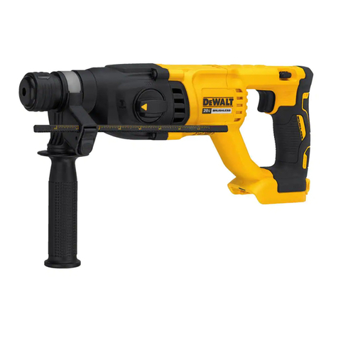
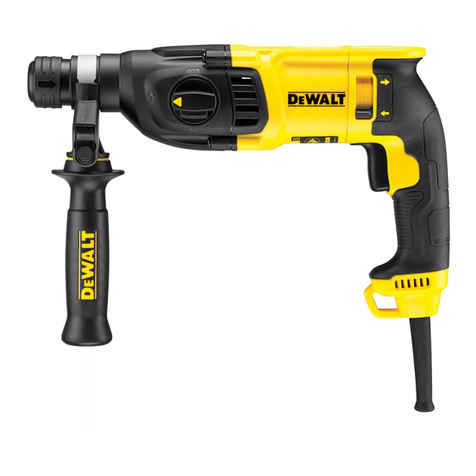
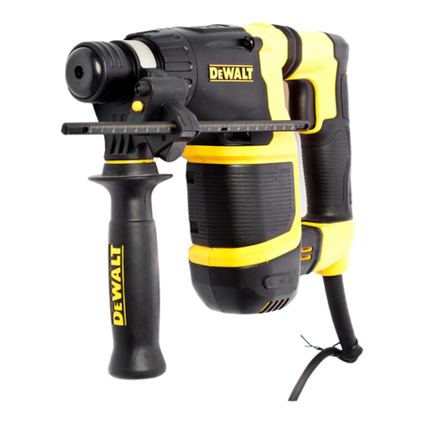
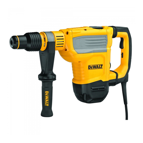
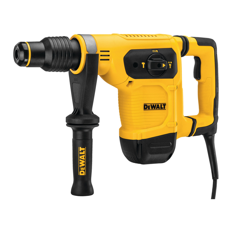
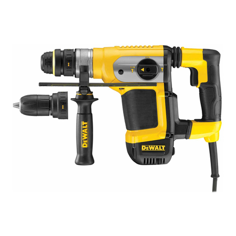
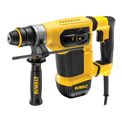
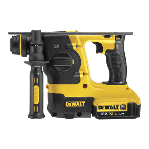
DeWalt D25413 User manual

If you have questions or comments, contact us.
Pour toute question ou tout commentaire, nous contacter.
Si tiene dudas o comentarios, contbctenos.
iNSTRUCTiON MANUAL
GUIDE D'UTILISATION
MANUAL DE INSTRUCCIONES
INSTRUCTIVO DE OPERACION, CENTROS DE SERVICIO Y P©LIZA DE
GARANT[A. ADVERTENClA: LEASE ESTE INSTRUCTIVO ANTES DE
USAR EL PRODUCTO.
®
D25413, D25415, D25430
1 1/8" (30 ram) Heavy Duty Rotary Hammer
Marteau rotatif industriel, 30 mm (1 1/8 po)
Martillo rotativo para trabajos pesados de 30 mm (1 1/8")

Definitions: Safety Guidelines
The definitions below describe the level of severity for each
signal word, Please read the manual and pay attention to these
symbols.
_.DANGER: Indicates an imminently hazardous situation
which, if not avoided, will result in death or serious injury.
i_,WARNING: Indicates a potentially hazardous situation which,
if not avoided, could result in death or serious injury.
_CAUTION: Indicates a potentially hazardous situation which,
if not avoided, may result in minor or moderate injury.
NOTICE: Indicates a practice not related to personal injury
which, if not avoided, may result in property damage.
.J
IF YOU HAVE ANY QUESTIONS OR COMMENTS ABOUT THIS OR
ANY DEWALT TOOL, CALL US TOLL FREE AT: 1-800-4-DEWALT
(1=800=433=9258}.
WARNING: To reduce the risk of injury, read the instruction
manual.
General Power Tool Safety Warnings
_WARNING! Read all safety warnings and all instructions.
Failure to follow the warnings and instructions may result in
electric shock, fire and/or serious injury.
SAVE ALL WARNINGS AND iNSTRUCTiONS
FOR FUTURE REFERENCE
The term "power tool" in the warnings refers to your mains-operated
(corded) power tool or battery-operated (cordless) power tool.
1} WORK AREA SAFETY
a) Keep work area clean and well lit, C/uttered or dark areas
invite accidents.
b) Do not operate power tools in explosive atmospheres,
such as in the presence of flammable liquids, gases or
dust. Power tools create sparks which may ignite the dust or
fumes.
c) Keep children and bystanders away while operating a
power tool Distractions can cause you to lose control
2} ELECTRICAL SAFETY
a) Power tool plugs must match the outlet. Never modify
the plug in any way. Do not use any adapter plugs with
earthed (grounded) power tools. Unmodified plugs and
matching outlets will reduce risk of electric shock.
b) Avoid body contact with earthed or grounded surfaces
such as pipes, radiators, ranges and refrigerators. There
is an increased risk of electric shock if your body is earthed or
grounded.
c) Do not expose power tools to rain or wet conditions.
Water entering a power too/will increase the risk of electric
shock.
d) Do not abuse the cord. Never use the cord for carrying,
pulling or unplugging the power tool Keep cord away
from heat, oil, sharp edges or moving parts. Damaged or
entangled cords increase the risk of electric shock.

e)Whenoperatingapower tool outdoors, use an extension
cord suitable for outdoor use. Use of a cord suitable for
outdoor use reduces the risk of electric shock.
If operating apowertool in a damp location is unavoidable,
use a ground fault circuit interrupter (GFCI) protected
supply. Use of a GFCI reduces the risk of electric shock.
3} PERSONAL SAFETY
a) Stay alert, watch what you are doing and use common
sense when operating a power tool Do not use a power
tool while you are tired or under the influence of drugs,
alcohol or medication. A moment of inattention while
operating power tools may result in serious personal injury.
b) Use personal protective equipment. Always wear eye
protection. Protective equipment such as dust mask, non-
skid safety shoes, hard hat, or hearing protection used for
appropriate conditions will reduce personal injuries.
c) Prevent unintentional starting. Ensure the switch is in
the off position before connecting to power source and/
or battery pack, picking up or carrying the tool Carrying
power tools with your finger on the switch or energizing power
tools that have the switch on invites accidents.
d) Remove any adjusting key or wrench before turning the
power tool on. A wrench or a key left attached to a rotating
part of the power tool may result in personal injury.
e) Do not overreach. Keep proper footing and balance at
all times. This enables better control of the power tool in
unexpected situations.
Dress properly. Do not wear loose clothing or jewelry.
Keep your hair, clothing and gloves away from moving
parts. Loose clothes, jewelry or long hair can be caught in
moving parts.
g) If devices are provided for the connection of dust
extraction and collection facilities, ensure these are
connected and properly used. Use of dust collection can
reduce dust-related hazards.
4) POWER TOOL USE AND CARE
a) Do not force the power tool Use the correct power tool
for your application. The correct power tool will do the job
better and safer at the rate for which it was designed.
b) Do not use the power tool if the switch does not turn it
on and off. Any power tool that cannot be controlled with the
switch is dangerous and must be repaired.
c) Disconnect the plug from the power source and/or the
battery pack from the power tool before making any
adjustments, changing accessories, or storing power
tools. Such preventive safety measures reduce the risk of
starting the power tool accidentally.
d) Store idle power tools out of the reach of children and
do not allow persons unfamiliar with the power tool or
these instructions to operate the power tool Power tools
are dangerous in the hands of untrained users.
e) Maintain power tools. Check for misalignment or binding
of moving parts, breakage of parts and any other
condition that may affect the power tool's operation. If
damaged, have the power tool repaired before use. Many
accidents are caused by poorly maintained power tools.
Keep cutting tools sharp and clean. Properly maintained
cutting tools with sharp cutting edges are less likely to bind and
are easier to control
g) Use the power tool, accessories and tool bits, etc. in
accordance with these instructions, taking into account
the working conditions and the work to be performed.
Useofthepowertoo/foroperationsdifferentfromthose
intendedcouldresultinahazardoussituation.
5} SERVICE
a) Have your power tool serviced by a qualified repair
person using only identical replacement parts. This will
ensure that the safety of the power too/is maintained.
Additional Safety Rules for Heavy Duty
Rotary Hammers
•Wear ear protectors. Exposure to noise can cause hearing loss.
•Use auxiliary handle(s), if supplied with the tool. Loss of
control can cause personal injury.
•Hold power tools by insulated gripping surfaces when
performing an operation where the cutting accessory may
contact hidden wiring or its own cord. Cutting accessory
contacting a "live" wire may make exposed metal parts of the
power tool "live" and could give the opeartor an electric shock.
•Use clamps or other practical way to secure and support
the workpiece to a stable platform. Holding the work by hand
or against your body is unstable and may lead to loss of control
•Wear safety goggles or other eye protection. Hammering
operations cause chips to fly.Flyingparticles can cause permanent
eye damage. Wear a dust mask or respirator for applications
that generate dust. Ear protection may be required for most
applications.
•Keep a firm grip on the tool at all times. Do not attempt
to operate this tool without holding it with both hands.
Operating this tool with one hand will result in loss of control
Breaking through or encountering hard materials such as re-bar
may be hazardous as well.
•Do not operate this tool for long periods of time. Vibration
caused by hammer action may be harmful to your hands and
arms. Use gloves to provide extra cushion and limit exposure by
taking frequent rest periods.
•Do not recondition bits yourself. Chisel reconditioning should
be done by an authorized specialist. Improperly reconditioned
chisels could cause injury.
•Wear gloves when operating tool or changing bits. Accessible
metal parts on the tool and bits may get extremely hot during
operation. Small bits of broken material may damage bare hands.
•Neverlay the tooldown untilthe bithas come to a complete
stop. Moving bits could cause injury.
•Do not strike jammed bits with a hammer to dislodge them.
Fragments of metal or material chips could dislodge and cause
injury.
•Keep the power cord away from the rotating bit. Do not
wrap the cord around any part of your body. An electric cord
wrapped around a spinning bit may cause persona/injury and loss
of control.
•Do not overheat the bit (discoloration) while grinding a new
edge. Badly worn chisels require reforging. Do not reharden and
temper the chisel
•Air vents often cover moving parts and should be avoided.
Loose clothes, jewelry or long hair can be caught in moving parts.
•An extension cord must have adequate wire size (AWG
or American Wire Gauge) for safety. The smaller the gauge
number of the wire, the greater the capacity of the cable, that is
16 gauge has more capacity than 18 gauge. An undersized cord
will cause a drop in line voltage resulting in loss of power and
overheating. When using more than one extension to make up the
total length, be sure each individual extension contains at least the

minimumwiresize.Thefollowingtableshowsthecorrectsizeto
usedependingoncordlengthandnameplateampererating.Ifin
doubt,usethenextheaviergauge.Thesmallerthegaugenumbed
theheavierthecord.
Minimum Gauge for Cord Sets
Volts Total Length of Cord
More
Than
Ampere
Rating 120 V in Feet (meters)
25 50 100 150
(7.6) (15.2) (30.5) (45.7)
50 1O0 200 300
(15.2) (30.5) (61.0) (91.4)
240 V
Not
More
Than
0 6 18 16 16 14
6 10 18 16 14 12
10 12 16 16 14 12
12 16 14 12 Not Recommended
AWG
,_ WARNING: ALWAYS use safety glasses. Everyday eyeglasses are
NOT safety glasses. Also use face or dust mask if cutting operation is
dusty. ALWAYS WEAR CERTIFIED SAFETY EQUIPMENT_
•ANSI Z87.1 eye protection (CAN/CSA Z94.3),
ANSI $12.6 ($3.19) hearing protection,
•NIOSH/OSHA/MSHA respiratory protection.
,_WARNING: Some dust created by power sanding, sawing,
grinding, drilling, and other construction activities contains chemicals
known to the State of Califomia to cause cancer, birth defects or other
reproductive harm. Some examples of these chemicals are."
lead from lead-based paints,
crystalline silica from bricks and cement and other masonry
products, and
arsenic and chromium from chemically-treated lumbe_
Your risk from these exposures varies, depending on how often you
do this type of work. To reduce your exposure to these chemicals."
work in a well ventilated area, and work with approved safety
equipment, such as those dust masks that are specially designed to
filter out microscopic particles.
Avoid prolonged contact with dust from power sanding,
sawing, grinding, drilling, and other construction activities.
Wear protective clothing and wash exposed areas with
soap and water. Allowing dust to get into your mouth, eyes, or
lay on the skin may promote absorption of harmful chemicals.
i_,WARNING: Use of this tool can generate and/or disperse dust,
which may cause serious and permanent respiratory or other
injury. Always use NIOSH/OSHA approved respiratory protection
appropriate for the dust exposure. Direct particles away from face
and body.
_WARNING: Always wear proper personal hearing protection
that conforms to ANSI $12.6 ($3.19) during use. Under some
conditions and duration of use, noise from this product may
contribute to hearing loss.
The label on your tool may include the following symbols. The
symbols and their definitions are as follows."
V.............. volts
Hz............ hertz
min .......... minutes
---. ...... direct current
(_)............ Class I Construction
(grounded)
[] ............ Class II Construction
(double insulated)
A........... amperes
W.......... watts
........ alternating current
_, ........ alternating or
direct current
no ......... no load speed
n........... rated speed
.......... earthing terminal

.../min..... per minute _ .......... safety alert
IPM .......... impacts per minute symbol
BPM ........ beats per minute SPM .....strokes per minute
RPM ........ revolutions per sfpm .....surface feet per
minute minute
SAVE THESE INSTRUCTIONS
FOR FUTURE USE
Motor
Be sure your power supply agrees with the nameplate marking.
Voltage decrease of more than 10% will cause loss of power and
overheating. DEWALT tools are factory tested; if this tool does not
operate, check power supply.
COMPONENTS (Fig. 1)
_WARNING: Never modify the power tool or any part of it. Damage
or personal injury could result.
A. Trigger switch
B. Main handle
C. Side handle
D. Depth rod
(only D25413 & D25415)
E. Depth rod release button
INTENDED USE
F. Chuck
G. Mode selection dial
H. Mode selector button
I. Reversing lever
(only D25413 & D25415)
J. Handle shocks
These heavy duty rotary and chipping hammers are designed for
professional concrete drilling and chiseling applications.
DO NOT use under wet conditions or in presence of flammable
liquids or gases.
FIG. 1
U
H

These heavy duty rotary hammers are professional power tools.
DO NOT let children come into contact with the tool. Supervision is
required when inexperienced operators use this tool.
ADJUSTMENTS
WARNING: To reduce the risk of injury, turn unit off and
disconnect it from power source before installing and
removing accessories, before adjusting or when making
repairs. An accidental start-up can cause injury.
Side Handle (Fig. 2)
AWARNING: To reduce the risk ofpersona/ FIG.2
injury, ALWAYS operate the tool with the
side handle properly installed and securely
tightened. Failure to do so may result in the
side handle slipping during tool operation
and subsequent loss of control Hold tool
with both hands to maximize control
A side handle comes assembled with this I
rotary hammer. The side handle (C) can be
fitted to suit both right-hand and left-hand
users.
TO ADJUST THE SIDE HANDLE
1. Loosen the side handle (C) by turning it O
counterclockwise.
2. Rotate the side handle to the desired
position.
3. Tighten the side handle by turning it
clockwise until you are sure the side
handle won't slip.
TO CHANGE SIDES
For right-hand users: slide the side handle clamp over the chuck,
handle at the left.
For left-hand users: slide the side handle clamp over the chuck,
handle at the right.
Trigger Switch (Fig. 1)
Tostart the rotary hammer, depress the trigger switch (A).To stop
rotary hammer, release the switch.
The variable speed trigger switch (A) permits speed control. The
farther the trigger switch is depressed, the higher the speed of the
rotary hammer.
NOTE: Use lower speeds for starting holes without a center punch,
drilling in metal, plastics or ceramics, or driving screws. Higher speeds
are better for drilling in wood and composition board and for using
abrasive and polishing accessories.
Mode Selector (Fig. 3)
NOTICE: Tool must come to a FIG.3
complete stop before activating the
mode selector button or damage to the
tool may result.
DRILL-ONLY MODE
To use drill-only mode, press mode
selector button (H) and turn the mode
selection dial (G) so the yellow arrow
points to the corresponding symbol as
shown. Use drill-only mode for wood,
metal, and plastics.

HAMMERDRILL MODE "" "r
To use hammerdrill mode, press the mode selector button (H) and
turn the mode selection dial (G) so the yellow arrow points to the
corresponding symbol as shown. Use this mode for masonry drilling.
HAMMER-ONLY MODE T
For light chiseling, press the mode selector button (H) and turn
the mode selection dial (G) so the yellow arrow points to the
corresponding symbol as shown.
NOTE: The yellow arrow on the mode selection dial MUST be
aligned with the one of the symbols at all times. There are no
operable positions between the positions.
E=Clutch and Indicator Light (Fig. 4)
(D25415 ON LY}
The e-clutch offers increased user FIG.4
comfort and safety through an
on-board anti-rotation technology
capable of detecting if the user loses J
control of the hammer. When a jam is
detected, the torque and speed are
reduced instantly. This feature prevents
self rotation of the tool reducing the
occurrence of wrist injuries.
The red indicator LED (J)lights up the electronic clutch is engaged in
any mode except the chipping mode.
Quick Change SDS Chuck (Fig. 5)
(D25415 ONLY) FIG.5
The SDS chuck can be easily removed
by turning the collar (K) into the
unlocked position to release the chuck.
The SDS chuck can be easily attached
by inserting the chuck into the spindle
of the tool and turning the collar to the K
locked position. The chuck will click
when properly installed.
Inserting and
Removing SDS Plus ®
Accessories (Fig. 1)
AWARNING: Burn hazard. ALWAYS wear gloves when changing
bits. Accessible metal parts on the tool and bits may get extremely
hot during operation. Small bits of broken material may damage bare
hands.
_, WARNING: Do not attempt to tighten or loosen drill bits (or any
other accessory) by gripping the front part of the chuck and turning
the tool on. Damage to the chuck and personal injury may occu_
To insert bit, insert shank of bit about 3/4" (19 mm), no further than
7/8" (22 mm) into chuck. Push and rotate bit until it locks in place. The
bit will be securely held.
To release bit, pull the chuck (F)back and remove the bit.
OP£RATION
AWARNING: To reduce the risk of injury, turn unit off
and disconnect it from power source before installing and
removing accessories, before adjusting or when making
repairs. An accidental start-up can cause injury.

Proper Hand Position (Fig. 6)
_WARNING: Toreduce the risk of serious personal injur!,ALWAYS
use proper hand position as shown in Fig. 6.
AWARNING: Toreduce the risk of serious personal injur!,ALWAYS
hold securely in anticipation of a sudden reaction.
Proper hand position requires one hand on the side handle (C),with
the other hand on the main handle (D).
FIG.6
FIG. 7
Depth Rod (Fig. 7)
(ONLY FOR D25413 & D25415}
TO ADJUST THE DEPTH ROD
1. Push in and hold the depth rod release button (E) on the side
handle.
2. Move the depth rod (D) so the distance between the end of the
rod and the end of the bit equals the desired drilling depth.
3. Release the button to lock rod into position. When drilling with the
depth rod, stop when end of rod reaches surface of material.
Reversing Lever (Fig. 8)
(ONLY FOR D25413 & D25415)
The reversing lever (H) is used to reverse the rotary hammer for
backing out fasteners or jammed bits in drill-only mode.
AWARNING: When reversing to clearjammed bits, be ready for
strong reactive torque.
To reverse the rotary hammer, turn it off and position the reversing
lever (H) to the right.
Toposition the lever for forward operation, turn the rotary hammer off
and push the reversing lever (H)to the left.
FIG.8

Drilling
(ONLY FOR D25413 &D25415)
1. Always unplug the drill when attaching or changing bits or
accessories.
2. Always use sharp drill bits. For WOOD, use twist drill bits, spade
bits, power auger bits, or hole saws. For METAL, use steel twist
drill bits or hole saws. For MASONRY, such as brick, cement,
cinder block, etc., use carbide-tipped bits rated for percussion
drilling.
3. Be sure the material to be drilled is anchored or clamped firmly.
If drilling thin material, use a wood "back-up" block to prevent
damage to the material.
4. Always apply pressure in a straight line with the bit. Use enough
pressure to keep drill biting, but do not push hard enough to stall
the motor or deflect the bit.
5. Hold tool firmly to control the twisting action of the drill.
_, WARNING: Drill may stall if overloaded causing a sudden twist.
Always expect the stall. Grip the drill firmly with both hands to
control the twisting action and avoid injury.
6. IF DRILL STALLS, it is usually because it is being overloaded or
improperly used. RELEASE TRIGGER IMMEDIATELY, remove
drill bit from work, and determine cause of stalling. DO NOT
CLICK TRIGGER ON AND OFF IN AN ATTEMPT TO START A
STALLED DRILL -- THIS CAN DAMAGE THE DRILL.
7. To minimize stalling or breaking through the material, reduce
pressure on drill and ease the bit through the last fractional part
of the hole.
8. Keep the motor running when pulling the bit back out of a drilled
hole. This will help prevent jamming.
9. With variable speed drills there is no need to center punch
the point to be drilled. Use a slow speed to start the hole and
accelerate by squeezing the trigger harder when the hole is deep
enough to drill without the bit skipping out.
DRILLING IN METAL
Start drilling with slow speed and increaseto full power while applying
firm pressure on the tool. A smooth even flow of metal chips indicates
the proper drilling rate. Use a cutting lubricantwhen drilling metals.
The exceptions are cast ironand brass which should be drilled dry.
NOTE: Large [5/16" to 1/2" (7,6 mm to 13 mm)] holes in steel can
be made easier if a pilot hole [5/32" to 3/16" (3,8 mm to 5 mm] is
drilled first.
DRILLING IN WOOD
Start drilling with slow speed and increaseto full power while applying
firm pressure on the tool. Holes inwood can be made with the same
twist drills used for metal. These bits may overheat unless pulled out
frequently to clear chips from the flutes. For larger holes, use spade
bits, power auger bits, or hole saws. Work that is apt to splinter
should be backed up with a block of wood.
DRILLING iN MASONRY
When drilling in masonry, use carbide tipped bits rated for percussion
drilling and be certain that the bit is sharp. Use a constant and firm
force on the tool to drill most effectively. A smooth, even flow of dust
indicatesthe proper drilling rate.
HAMMERDRILL OPERATION
1. When drilling, use just enough force on the hammer to keep it
from bouncing excessively or "rising" off the bit. Too much force
will cause slower drilling speeds, overheating, and a lower drilling
rate.

2.Drillstraight,keepingthebitatarightangletothework.Donot
exertsidepressureonthebitwhendrillingasthiswillcause
cloggingofthebitflutesandaslowerdrillingspeed.
3.Whendrillingdeepholes,ifthehammerspeedstartstodropoff,
pullthebitpartiallyoutoftheholewiththetoolstillrunningtohelp
cleardebrisfromthehole.
4.Formasonry,usecarbide-tippedbitsormasonrybits.Asmooth
evenflowofdustindicatestheproperdrillingrate.
Chipping and Chiselling (Fig. 1)
1. Set the mode selector switch (G)to the hammering only position.
2. Insert the appropriate chisel and rotate it by hand to lock it.
3. Adjust the side handle (C) as required.
4. Be sure chisel is in contact with work surface before depressing
the trigger switch.
5. Always fully release the trigger switch when work is finished and
before unplugging.
MAINT£NANCE
i_WARNING: To reduce the risk of injury, turn unff off
and disconnect it from power source before installing and
removing accessories, before adjusting or when making
repairs. An accidental start-up can cause injury.
Motor Brushes
DEWALT uses an advanced brush system which automatically stops
the drill when the brushes wear out. This prevents serious damage
to the motor. New brush assemblies are available at authorized
DE.:.WALTservice centers. Always use identical replacement parts.
Cleaning
i_,WARNING: Blow dirt and dust out of all air vents with dean, dry air
at least once a week. To minimize the risk of eye injury, always wear
ANSI Z87.1 approved eye protection when performing this.
_WARNING: Never use solvents or other harsh chemicals for
cleaning the non-metallic parts of the tool These chemicals may
weaken the plastic materials used in these parts. Use a cloth
dampened only with water and mild soap. Never let any liquid get
inside the tool,"never immerse any part of the tool into a liquid.
Accessories
_,WARNING: Since accessories, other than those offered by
D_-:WALT,have not been tested with this product, use of such
accessories with this tool could be hazardous. Toreduce the risk of
injury, only D,_-:WALTrecommended accessories should be used with
this product.
Recommended accessories for use with your tool are available at
extra cost from your local dealer or authorized service center. If you
need assistance in locating any accessory, please contact DEWALT
Industrial Tool Co., 701 East Joppa Road, Baltimore, MD 21286,
call 1-800-4-DE.:.WALT(1-800-433-9258) or visit our website: www.
dewalt.com.MAXIMUM RECOMMENDED CAPACITIES
Maximum Capacity
R.RM.
BITS, Metal Drilling
Wood, Flat Boring
Optimum Capacity
No-load BPM
1-1/8" (28.5 mm) Concrete
0-820 (No Load)
1/2" (13 mm)
1-1/8" (28.5 mm)
1/2" - 1" (13 to 25 mm) Concrete
0-4,700
10

Repairs
To assure product SAFETY and RELIABILITY, repairs, maintenance
and adjustment (including brush inspection and replacement) should
be performed by a DEWALT factory service center, a DE.:.WALT
authorized service center or other qualified service personnel. Always
use identical replacement parts.
Register Online
Thank you for your purchase. Register your product now for:
• WARRANTY SERVICE: Registering your product will help you
obtain more efficient warranty service in case there is a problem
with your product.
,, CONFIRMATION OF OWNERSHIP: In case of an insurance
loss, such as fire, flood or theft, your registration of ownership will
serve as your proof of purchase.
FOR YOUR SAFETY: Registering your product will allow us to
contact you in the unlikely event a safety notification is required
under the Federal Consumer Safety Act.
Register online at www.dewalt.com/register.
Three Year Limited Warranty
DE.:.WALTwill repair,without charge, any defects due to faulty materials
or workmanship for three years from the date of purchase. This
warranty does not cover part failure due to normal wear or tool
abuse. For further detail of warranty coverage and warranty repair
information, visit www.dewalt.com or call 1-800-4-DEWALT (1-800-
433-9258). This warranty does not apply to accessories or damage
caused where repairs have been made or attempted by others. This
warranty gives you specific legal rights and you may have other rights
which vary in certain states or provinces.
In addition to the warranty, DEi.:.WALTtools are covered by our:
1YEAR FREE SERVICE
DEWALT will maintain the tool and replace worn parts caused by
normal use, for free, any time during the first year after purchase.
90 DAY MONEY BACK GUARANTEE
If you are not completely satisfied with the performance of your
DEWALT Power Tool, Laser, or Nailer for any reason, you can return
it within 90 days from the date of purchase with a receipt for a full
refund - no questions asked.
LATIN AMERICA: This warranty does not apply to products sold
in Latin America. For products sold in Latin America, see country
specific warranty information contained in the packaging, call the local
company or see website for warranty information.
FREE WARNING LABEL REPLACEMENT: If your warning labels
become illegible or are missing, call 1-800-4-DEi.:.WALT(1-800-433-
9258) for a free replacement.
"nx××xk SI)S ROTARY HAMMER
SER._
TO_DUC_T_ RiSKOFI_JURY,USE_MUSTR_ADTHEI_STRUCTIONtV_NU_LALWAYS
USEP_O_E_EYEAND_S_I_ATORV_OTECTIOt_.ALWAYSUSESIOE_A_ LE./
PAR_DSM_URE__ESGOOE_SONES.ELUSUA_0_EB_P_E_ EMANUALOE
I_STRUCCIO_ES.SI_MPRESE_EBE_AU.EVA_L_P_OT_IONA_O_IAO_PA_
VISTAV_A_ U_SViAS_ESPI_TORI_S.SlEM_ _TI_C_ELM_N_0L_TEP_L!
AFIt_OEraINl_ls_ LES_IS_UESOEBL_SS_S.L'_TI_SAT_U__OIT_OUJOU_SU_ LE
_UI_EO'UTlUSATIO_.IL_AU_TOUJO_S_0RTE_r__'EQUIp_MEr_T__PROTEC_ION
_,WALTIt_USTRIA_TOOLCO._L_MOR_.i_ _1_ USA
11

D_finitions : lignes directrices en
rnati_re de s_curit_
Les definitions ci-dessous decrivent le niveau de danger pour
chaque mot-indicateur employe. Life le mode d'emploi et porter
une attention particuliere _.ces symboles.
_DANGER :indique une situation dangereuse imminente qui,
si elle n'est pas evitee, entrainera la mort ou des blessures
graves.
h_AVERTISSEMENT :indique une situation potentie//ement
dangereuse qui, si e//e n'est pas evitee, pourraff entra?ner /a
mort ou des blessures graves.
AATTENTION :indique une situation potentie//ement
dangereuse qui, si e//e n'est pas evitee, pourraff entra?ner des
blessures I_g_res ou mod_r6es.
AVIS :indique une pratique ne posant aucun risque de
dommages corporels mais qui par contre, si rien n'est faitpour
I'evited pourrait poser des risques de dommages mat6riels. J
POUR TOUTE QUESTION OU REMARQUE AU SUJET DE OET
OUTIL OU DE TOUT AUTRE OUTIL DEWALT, COMPOSE LE
NUMC:RO SANS FRAIS : 1-800-4-DEWALT (1-800-433-9258}.
_VERTISSEMENT :afin de reduire le risque de blessures, life
/e mode d'emp/oi de/'outi/.
Avertissernents de s_curit_ g_n_raux
pour les outils _lectriques
_VERTISSEMENT !Life tous les avertissements de
s6curit6 et toutes les directives. Le non-respect des 12
avertissements et des directives pourrait se solder par un
choc dectrique, un incendie et/ou une blessure grave.
CONSERVER TOUSLES AVERTISSEMENTS
ET TOUTES LES DIRECTIVES POUR UN
USAGE ULTERIEUR
Le terme _outil dectrique _cite clans les avertissements se rapporte
votre outil electrique a alimentation sur secteur (avec ill) ou par piles
(sansfil).
1} SECURITi "=DU LIEU DE TRAVAIL
a) Tenir I'aire de travail propre et bien 6clair6e, Les Iieux
encombres ou sombres sont propices aux accidents.
b) Ne pas faire fonctionner d'outils 61ectriques clans un
milieu d_flagrant, tel qu'en pr6sence de liquides, de
gaz ou de poussi_res inflammables. Les outi/s e/ectriques
produisent des etincelles qui pourraient enf/ammer /a poussiere
ou les vapeurs.
c) Eloigner les enfants et les personnes b proximit6 pendant
I'utilisation d'un outil 61ectrique. Une distraction pourrait en
faire perdre la ma?trisea I'utilisateu_
2) SECURITE EN MATI#RE D'#LECTRICIT#
a) Les fiches des outils 61ectriques doivent correspondre
la prise. Ne jamais modifier la fiche d'aucune faqon.
Ne jamais utiliser de fiche d'adaptation avec un outil
61ectrique mis _la terre. Le risque de choc dectrique sera
reduit par/'uti/isation de fiches non modifiees correspondant
la prise.
b) Eviter tout contact physique avec des surfaces mises _la
terre comme des tuyaux, des radiateurs, des cuisini_res
et des r6frig_rateurs. Le risque de choc dectrique est plus
deve si votre corps est mis a la terre.

c) Ne pas exposer les outils 61ectriques b la pluie ou
I'humidit6. La penetration de /'eau dans un outi/ dectrique
augmente le risque de choc dectrique.
d) Ne pas utiliser le cordon de faqon abusive. Ne jamais
utiliser le cordon pour transporter, tirer ou d_brancher
un outil 61ectrique. Tenir le cordon 61oLgn_ de la chaleur,
de I'huile, des bords tranchants et des pi_ces mobiles.
Les cordons endommages ou enchev6tres augmentent /es
risques de choc dectrique.
e) Pour I'utilisation d'un outil 61ectrique _ I'ext6rieur, se
servir d'une rallonge convenant _cette application.
L'uti/isation d'une ra//onge conque pour/'exterieur reduira /es
risques de choc dectrique.
S'il est impossible d'6viter I'utilisation d'un outil
61ectrique clans un endroit humide, brancher I'outil clans
une prise ou sur un circuit d'alimentation dot_s d'un
disjoncteur de fuite _ la terre (GFCI). L'utilisation de ce type
de disjoncteur reduit /es risques de choc dectrique.
3} SECURITi_ PERSONNELLE
a) Etre vigilant, surveiller le travail effectu6 et faire preuve
de jugement Iorsqu'un outil 61ectrique est utilis6. Ne
pas utiliser d'outil 61ectrique en cas de fatigue ou sous
I'influence de drogues, d'alcool ou de m_dicaments. Un
simple moment d'inattention en uti/isant un outi/ dectrique pout
entra_nerdes b/essures corpore//es graves.
b) Utiliser des 6quipements de protection individuelle.
Toujours porter une protection oculaire. L'uti/isation
d'equipements de protection comme un masque antipoussiere,
des chaussures antiderapantes, un casque de securite ou des
protecteurs auditifs Iorsque la situation le requiert reduira les
risques de blessures corporelles.
13
c) Emp@cher los d6marrages intempestifs. S'assurer que
I'interrupteur se trouve _la position d'arr@t avant de
relier I'outil _une source d'alimentation et/ou d'ins6rer
un bloc-piles, de ramasser ou de transporter I'outiL
Transporter un outi/ dectrique a/ors que /e doigt repose sur
I'interrupteur ou brancher un outil dectrique dont I'interrupteur
est a la position de mamhe risque de provoquer un accident.
d) Retirer toute cl6 de r6glage ou cl_ avant de d_marrer
I'outiL Une cle ou une cle de reglage attachee a une pattie
pivotante de I'outil dectrique peut provoquer des blessures
corporelles.
e) Ne pas trop tendre los bras. Conserver son 6quilibre en
tout temps. Ce/a permet de mieux ma?triser /'outi/ dectrique
dans les situations imprevues.
S'habiller de mani_re appropri6e. Ne pas porter de
v@tements amples ni de bijoux. Garder los cheveux, los
vetements et los gants _I'ecart des pieces mobiles. Les
v6tements amples, les bijoux ou les cheveux longs risquent de
rester coinces clans les pieces mobiles.
g) Si des composants sont fournis pour le raccordement de
dispositifs de d_poussi6rage et de ramassage, s'assurer
que ceux-ci sont bien raccord_s et utilis6s. L'uti/isation
d'un dispositif de depoussierage peut reduire /es dangers
engendres par les poussieres.
4) UTILISATION ET ENTRETIEN D'UN OUTIL ELECTRIQUE
a) Ne pas forcer un outil 6lectrique. Utiliser I'outi161ectrique
appropri6 b I'application. L'outi/ e/ectrique approprie
effectuera un meilleur travail, de faqon p/us sore eta/a vitesse
pour laquelle il a ere conqu.
b) Ne pas utiliser un outil _lectrique dont I'interrupteur
est d_fectueux. Tout outi/ dectrique dont /'interrupteur est
defectueux est dangereux et doit _tre repare.

c) D_brancher la fiche de la source d'alimentation et/ou du
bloc-piles de I'outil 61ectrique avant de faire tout r6glage
ou changement d'accessoire ou avant de ranger I'outiL
Ces mesures preventives reduisent /es risques de demarrage
accidentel de I'outil dectrique.
d) Ranger los outils 61ectriques hers de la port6e des
enfants et ne permettre _aucune personne n'6tant
pas famili_re avec un outil 61ectrique ou son mode
d'emploi d'utiliser cet outiL Les outi/s dectriques deviennent
dangereux entre les mains d'utilisateurs inexperimentes.
e) Entretien des outils 61ectriques. V6rifier si los pi_ces
mobiles sent mal align6es ou coinc_es, si des pi_ces sent
bris6es ou pr6sentent toute autre condition susceptible
de nuire au ben fonctionnement de I'outil 61ectrique.
En cas de dommage, faire r6parer I'outil 61ectrique
avant toute nouvelle utilisation. Beaucoup d'accidents sent
causes par des out/Is dectriques mal entretenus.
S'assurer que los outils de coupe sent aiguis6s et
propres. Los outi/s de coupe bien entretenus et affOtes
sent moins susceptib/es de se coincer et sent plus faci/es
ma_trise_
g) Utiliser I'outil 61ectrique, les accessoires, les forets,
etc. conform6ment aux pr6sentes directives en tenant
compte des conditions de travail et du travail _effectuer.
L'utilisation d'un outil dectrique pour toute operation autre que
celle pour laquelle il a ere conqu est dangereuse.
5) Ri_PARATION
a) Faire r6parer I'outil 61ectrique par un r6parateur
professionnel en n'utilisant que des pi_ces de rechange
identiques. Ce/a permettra de maintenir une uti/isation
securitaire de/'outi/dectrique.
Consignes de s_curit_ additionnelles
propres aux rnar*eaux rotatifs industriels
,Porter un dispositif de protection auditif. Le bruit en emanant
pourrait occasionner une perte de/'acuite auditive.
•Utiliser lalles poign6e(s) auxiliaire(s) si fournie(s) avec
I'outiL Une perte de contr6/e de/'outi/pourrait occasionner des
dommages corporels.
Tenir I'outil 61ectrique par les surfaces isol_es pr6vues
cet effet pendant toute utilisation ob I'organe de coupe
pourrait entrer en contact avec des ills 61ectriques caches
ou son propre cordon. Tout contact de/'organe de coupe avec
un fil sous tension mettra les parties metalliques exposees de
I'outil dectrique sous tension et dectrocutera I'utilisateu_
•Utiliser des serre-joints ou tout autre moyen pour fixer et
immobiliser le mat_riau sur une surface stable. Tenir/a piece
/a main ou centre son corps offre une stabi/ite insuffisante qui
pourrait vous en faireperdre le contrde.
Porter des lunettes de protection ou route autre protection
oculaire. Le matte/age pourrait faire vo/tiger des eclats. Des
particules volantes pourraient occasionner des dommages
oculaires permanents. Porter un masque anti-poussieres ou
un appareil de protection des voles respiratoires pour toute
application pmductrice de poussieres. Une protection auditive
peut s'averer necessaire pour la plupart des applications.
Maintenir syst_matiquement I'outil fermement. Ne pas
tenter d'utiliser cet outil sans le maintenir _deux mains.
Le fair d'uti/iser cet outi/ a une main pourra vous en faire perdre /e
contr61e. Traverser ou rencontrer des materiaux durs, comme les
armatures, peut aussi s'averer dangereux.
14

•Ne pas faire fonctionner cet outil durant de Iongues
p6riodes. Les vibrations causees par/a percussion du marteau
peuvent 6tre nuisibles pour vos mains et vos bras. Utiliser des
gants pour amortir davantage les vibrations et Iimiter /'exposition
I'outil par de frequentes periodes de repos.
•Ne pas remettre _ neuf les m_ches vous-m@me. La remise
neuf du burin dolt 6tre rea/isee par un specia/iste autorise. Les
burins mal remis a neuf peuvent causer des blessures.
•Porter des gants pour utiliser I'outil ou pour changer
les m_ches. Les pieces meta//iques accessib/es de /'outi/ et
les meches peuvent devenir extr6mement chaudes durant le
fonctionnement de I'outil. De petits momeaux de materiau qui se
detachent peuvent endommager les mains nues.
Ne jamais d_poser I'outil tant que la m_che ne s'est pas
compl_tement arr@t_e. Les meches mobiles peuvent provoquer
des blessures.
•Ne pas frapper sur los m_ches coinc6es avec un marteau
pour les d_loger. Des fragments de metal ou des copeaux de
materiau peuvent se ddoger et causer des blessures.
Les burins I_g_rement us6s peuvent @tre r6affQt6s par le
meulage.
•Tenir 61oign6 le cordon d'alimentation de la m_che rotative.
Ne pas enrouler le cordon autour de toute partie du corps.
Un cordon d'a/imentation enroule autour d'une meche rotative
risque de causer des blessures corporelles et une perte de
ma_trise de I'outil.
Ne pas surchauffer la m_che (d6coloration) durant le
meulage d'un nouveau tranchant. Les burins ma/ uses
demandent a 6tre de nouveau forges. Ne pas durcir nine faire
revenir les burins.
Prendre des pr6cautions _proximit_ des 6vents, car ils
cachent des pi_ces mobiles. V6tements amp/es, bijoux ou
cheveux longs risquent de rester coinces clans ces pieces mobiles.
Pour la s6curit6 de I'utilisateur, utiliser une rallonge de
calibre ad_quat (AWG, American Wire Gauge [calibrage
am6ricain normalis_ des ills 61ectriques]). Plus/e calibre est
petit, et plus sa capacite est grande. Un calibre 16, par exemple,
a une capacite superieure a un calibre 18. L'usage d'une rallonge
de calibre insuffisant causera une chute de tension qui entra?nera
perte de puissance et sumhauffe. Si plus d'une rallonge est utilisee
pour obtenir une certaine Iongueud s'assurer que chaque rallonge
presente au moins le calibre de filminimum. Le tableau ci-dessous
illustre les calibres a utiliser selon la Iongueur de rallonge et
I'intensite nominale indiquee sur la plaque signaletique. En cas
de doute, utiliser le calibre suivant. Plus le calibre est petit, plus la
rallonge peut supporter de courant.
Calibres minimaux des rallonges
volts Longueur totale de cordon
en m_tres (pieds}
Intensit_ (en 120 V 7,6 15,2 30,5 45,7
amperes}
Sup6rieur
0
6
10
12
Inf6rieur
6
10
12
240 V (25) (50)
15,2 30,5
(50) (100)
AWG
18 16
18 16
16 16
(100) (150)
61,0 91,4
(200) (300)
16 14
14 12
14 12
Non
12 recommande
16 14
15

1_AVERTISSEMENT:porter SYSTEMATIQUEMENT des lunettes
de protection. Les lunettes courantes NE sont PAS des lunettes de
protection. Utiliser aussi un masque antipoussieres si la decoupe
doit en produire beaucoup. PORTER SYSTEMATIQUEMENT UN
EQUIPEMENT DE SECURITE HOMOL OGUE :
•Protection oculaire ANSI Z87.1 (CAN/CSA Z94.3) •
Protection auditive ANSI S 12.6 ($3.19) •
Protection des voies respiratoires NIOSH/OSHA/MSHA.
•#.AVEFtTISSEMENT :les scies, meules, ponceuses, perceuses
ou autres outils de construction peuvent produire des poussieres
contenant des produits chimiques reconnus par I'Etat califomien
pour causer cancers, malformations congenitales ou 6tre nocifs au
systeme reproducteu_ Parmi ces produits chimiques, on retrouve :
Le plomb dans les peintures a base de plomb •
La silice cristallisee dans les briques et le ciment, ou autres
produits de magonnerie ; et
L'arsenic et le chrome dans le bois ayant subi un traitement
chimique.
Le risque associe a de telles expositions varie selon la frequence
laquelle on effectue ces travaux. Pour reduire toute exposition aces
produits "travailler clans un endroit bien aere, en utilisant du materiel
de securite homologue, tel un masque antipoussieres specialement
conqu pour flitter les particules micmscopiques.
Limiter route exposition prolong6e avec les poussi6res
provenant du ponqage, sciage, meulage, perqage ou toute
autre activit6 de construction. Porter des v6tements de
protection et nettoyer _I'eau savonneuse les parties du
corps expos6es. Le far de/aisser/a poussiere penetrer clans/a
bouche, /esyeux ou /apeau peut favoriser /'absorption de produits
chimiques dangereux.
_AVERTISSEMENT :cet outil peut produire et/ou repandre
de la poussiere susceptible de causer des dommages serieux et
permanents au systeme respiratoire. Utiliser systematiquement un
appareil de protection des voies respiratoires homologue par le
NIOSH ou I'OSHA. Diriger les particules clans le sens oppose au
visage et au corps.
i_AVERTISSEMENT :pendant I'utilisation, porter
syst6matiquement une protection auditive individuelle
ad6quate homologu6e ANSi $12.6 ($3.19). Sous certaines
conditions et suivant /a duree d'uti/isation, /e bruit emanant de ce
produit pourrait contribuer a une perte de I'acuite auditive.
L'etiquette apposee sur votre outil peut inclure les symboles
suivants. Les symboles et leur definition sont indiques ci-apres "
V................... volts
Hz................. hertz
min ............... minutes
---. ........... courant continu
(_)................. classe I fabrication
(mis a la terre)
[] ................. fabrication classe II
(double isolation)
.../min .......... par minute
IPM ............... impacts par minute
BPM ............. battements par
minute
SPM (FPM)... frequence
par minute
A............. amperes
W............ watts
,x, .......... courant alternatif
_-,.......... courant altematif
ou continu
no ........... vitesse a vide
n............. vitesse nominale
@ ...........borne de terre
............ symbole
d'avertissement
sfpm .......pieds Iineaires
par minute (plpm)
r/min ....... tours par minute
16

CONSERVER CES CONSIGNES POUR
UTILISATION ULTERIEURE
Moteur
S'assurer que le bloc d'alimentation est compatible avec I'inscription
de la plaque signaletique.Une diminution de tension de plus de 10 %
provoquera une perte de puissance et une surchauffe. Les outils
DEWALTsont testes en usine ; si cet outil ne fonctionne pas, verifier
I'alimentation electrique.
DESCRIPTION (Fig. 1)
AAVERT/SSEMENT :ne jamais modifier I'outil dectrique ni aucun
de ses composants, car il y a risques de dommages corporels ou
materiels,
A. G_,chette
B. Poignee principale
C. Poignee laterale
D. Tige de profondeur
(D25413 et D25415
seulement)
E. Bouton de degagement de la
tige de profondeur
USAGE PREVU
F. Mandrin
G. Cadran de selection de
mode
H. Bouton selecteur de mode
I. Levier d'inversion
(D25413 et D25415
seulement)
J. Amortisseurs de poignee
Ces marteaux burineurs et rotatifs industriels ont ete con_us pour le
per_age et le ciselage professionnel du beton.
NE PAS les utiliser en milieu ambiant humide ou en presence de
liquides ou de gaz inflammables.
Ces marteaux rotatifs industriels sont des outils electriques de
professionnels. NE PAS les laisser _, la portee des enfants. Une
supervision est necessaire aupres de tout utilisateur non experimente.
FIG. 1 H
U
AJUSTEMENTS
_,AVERTISSEMENT :pour r6duire le risque de blessures,
6teindre I'appareil et le d_brancher avant d'installer ou de
retirer tout accessoire et avant d'effectuer des r6glages ou des
r6parations. Un demarrage accidente/ peut provoquer des b/essures.
17

Poign_e lat_rale (Fig. 2)
AAVERTISSEMENT :pour reduire tout FIG.2
risque de dommages corpore/s, uti/iser
SYSTE-MATIQUEMENT I'outil avec sa
poignee /atera/e insta//ee correctement et
so/idement arrimee. Tout manquement
cette directive pourrait faire que la poignee
laterale glisse pendant I'utilisation de I'outil
et entra_ner la perte du contr61e de celui-cL I
Maintenir I'outil fermement a deux mains
pour un contr61e maximum.
Ce marteau rotatif est equipe d'origine d'une
poignee laterale. La poignee laterale (C)peut
_tre installee pour pouvoir servir _,un droitier
ou _,un gaucher. O
INSTALLATION DE LA POIGN#E
LAT#RALE
3. Desserrez la poignee laterale (C) en la
faisant burner vers la gauche.
2. Faites tourner la poignee lateralesur laposition desiree.
3. Resserrez la poignee laterale en la faisant burner vers la droite.
POUR CHANGER DE C6TI_
Pour les droitiers : inserez le dispositif de fixation de la poignee
laterale sur le mandrin, avec la poignee _,gauche.
Pour les gauchers : inserez le dispositif de fixation de la poignee
laterale sur le mandrin, avec la poignee _,droite.
G_chette (Fig. 1)
Pour demarrer le marteau rotatif, appuyez sur lagS,chette (A). Pour
arr_ter le marteau rotatif, relS,chez lagS,chette.
18
La g_,chette a vitesse variable (A) permet de contr(_ler la vitesse.
Plus on appuie sur lagS,chette, plus la vitesse du marteau rotatif est
grande.
REMARQUE : utiliser une vitesse reduite pour commencer un trou
sans pointeau, pour percer le metal, les plastiques ou la ceramique,
ou enfoncer des vis. Les vitesses elevees sont recommandees pour
percer le bois et les panneaux d'agglomere, et pour utiliser des
accessoires abrasifs ou de polissage.
S_lecteur de mode (Fig. 3)
AViS :pour prevenir tout dommage FIG.3
materiel, attendre I'arr6t complet
de I'outil avant d'activer le bouton
sdecteur de mode.
MODE PERQAGE SEULEMENT ,_
Pour utiliser lemode pergage seulement,
appuyez sur le bouton selecteur de
mode (H) puis tournez le cadran de
selection de mode (G)jusqu'_, ce que
la fleche jaune pointe sur le symbole
correspondant, comme illustre. Utilisez
le mode pergage seulement pour le bois, le metal et les plastiques.
MODE MARTELAGE-PERFORAGE ""T
Pour utiliser le mode martelage-perforage, appuyez sur le bouton
selecteur de mode (H) puis tournez le cadran de selection de mode
(G)jusqu'_ ce que la fleche jaune pointe sur le symbole correspondant,
comme illustre. Utilisez ce mode pour percer la magonnerie.
MODE PERCUSSION SEULEMENT T
Pour du ciselage leger, appuyez sur le bouton selecteur de mode
(H) puis tournez le cadran de selection de mode (G)jusqu'_, ce que
la fl_che jaune pointe sur le symbole correspondant, comme illustre.

REMARQUE : la fleche jaune sur le cadran de selection de mode
DOlT constamment _tre alignee sur I'un des symboles. II n'existe
aucune position d'utilisation entre les symboles.
E-Clutch et Voyant (Fig. 4)
(D25415 SEULEMENT}
I'E-clutch offre _.I'utilisateur un surcroTt FIG.4
de confort et de securite au travers
d'une technologie integree anti-rotation
capable de detecter si I'utilisateur perd J
le contr<51e du marteau. En cas de
detection de grippage, le couple et la
vitesse sont reduits instantanement.
Cette fonctionnalite previent toute
rotation inopportune de I'outil,
reduisant ainsi les risques de blessures au poignet.
Le voyant DEL rouge (J) s'allumera Iorsque I'embrayage
electronique sera active en tout mode, excepte celui de burinage.
Mandrin SDS auto-serrant (Fig. 5)
(D25415 SEULEMENT} FIG.5
Le mandrin SDS peut _tre facilement
retire en tournant la bague (K) sur
la position deverrouillee qui libere le
mandrin.
Le mandrin SDS peut _tre facilement
installe en inserant le mandrin dans K
la broche de I'outil puis en tournant
la bague en position verrouillee. Le
mandrin emettra un clic Iorsqu'il sera
installe correctement.
installation et retrait des accessoires
SDS Plus MD (Fig. 1)
_AVERTISSEMENT :risques de brOlure. Uti/iser
SYSTEMATIQUEMENT des gants pour changer meche ou foret.
Les parties metalliques accessibles de I'outil et des meches/forets
pourraient s'averer brOlantes /ors de I'utilisation. De petits debris de
materiau pourraient aussi blesser les mains nues.
,_AVERTISSEMENT :ne pas essayer de resserrer ou desserrer
les meches (ou tout autre accessoire) en agrippant la pattie avant du
mandrin tout en mettant I'outil en mamhe. Cela pourrait endommager
le mandrin et poser des risques de dommages corporels.
Pour inserer une m_che, inserez la tige de m_che sur environ 19 mm
(3/4 po), 22 mm (7/8 po) maximum, dans le mandrin. Poussez et
faites tourner la m_che jusqu'_, ce qu'elle se verrouille en place. La
m_che sera maintenue fermement.
Pour lib_rer un foret, tirez le mandrin (F)vers I'arri_re puis retirez le
foret.
UTILISATION
_AVERTISSEMENT :pour r_duire le risque de blessures,
6teindre I'appareil et le d_brancher avant d'installer ou de
retirer tout accessoire et avant d'effectuer des r6glages ou des
r6parations. Un demarrage accidente/ peut provoquer des b/essures.
Position correcte des mains (Fig. 6)
AAVERTISSEMENT :pour reduire tout risque de dommages
corporels graves, utiliser SYSTEMATIQUEMENT la position correcte
des mains illustree en figure 6.
AAVEFtTISSEMENT :pour reduire tout risque de dommages
corporels graves, maintenir SYSTEMATIQUEMENT I'outil fermement
pour anticiper toute reaction soudaine de I'outil
19
Other manuals for D25413
9
This manual suits for next models
2
Table of contents
Languages:
Other DeWalt Rotary Hammer manuals

DeWalt
DeWalt D25415K User manual

DeWalt
DeWalt D25721 User manual

DeWalt
DeWalt DWC24K3 User manual

DeWalt
DeWalt DC232 User manual

DeWalt
DeWalt DCH775 User manual

DeWalt
DeWalt DW005K User manual

DeWalt
DeWalt D25614 User manual

DeWalt
DeWalt DCH243 User manual

DeWalt
DeWalt DCH273 User manual

DeWalt
DeWalt DCH172 User manual

DeWalt
DeWalt DW570K User manual

DeWalt
DeWalt DW004 User manual

DeWalt
DeWalt D25700 User manual

DeWalt
DeWalt DCH481 User manual

DeWalt
DeWalt D25413 User manual

DeWalt
DeWalt D25333 User manual

DeWalt
DeWalt 581054-00 User manual

DeWalt
DeWalt DW562 User manual

DeWalt
DeWalt D25614 User manual

DeWalt
DeWalt D25123 User manual