Dewetron TRIONet Product manual

TECHNICAL REFERENCE MANUAL
TRIONet
WELCOME TO
THE WORLD OF
DEWETRON!
Congratulations on your new device! It
will supply you with accurate, complete
and reproducible measurement results
for your decision making.
Look forward to the easy handling and
the flexible and modular use of your
DEWETRON product and draw upon
more than 30 years of DEWETRON ex-
pertise in measurement engineering.
ISO9001
EN ISO 14001
THE MEASURABLE DIFFERENCE.

Copyright © DEWETRON GmbH
This document contains informaon which is protected by copyright. All rights are reserved. Reproducon, adaptaon,
or translaon without prior wrien permission is prohibited, except as allowed under the copyright laws.
All trademarks and registered trademarks are acknowledged to be the property of their owners.

Preface
3
TRIONet • Technical reference • Prinng version 1.0.7 • October 15, 2021
Preface
Thank you!
Thank you very much for your investment in DEWETRON‘s unique data acquision systems. These are top-quality
instruments which are designed to provide you years of reliable service. This guide has been prepared to help you
get the most from your investment, starng from the day you take it out of the box, and extending for years into the
future.
This guide includes important startup notes, as well as safety notes and informaon about keeping your DEWETRON
system in good working condion over me. However, this manual cannot and is not intended to replace adequate
training.
This documentaon contains operang as well as safety and care instrucons that must be observed by the user. Fault-
less operaon can only be guaranteed by observing these instrucons.
Intended use
The compact, distributable TRIONet accepts any two of the mul-channel TRION series plug-in modules and connects
to any Windows computer via USB or Ethernet. Furthermore, TRIONet mainframes can be interconnected using Eth-
ernet. Because of the Ethernet interface, TRIONet mainframes can even be placed up to 100 meters apart from each
other.
System overview
The picture below shows an overview of the device and its connecons and ports.
INFORMATION
The amount and locaon of the connectors might vary from system to system and depend on the sys-
tem conguraon.
PC/laptop for storing and analyzing Measurement units
TRIONet
LAN/USB TRIONet
Fig. 1: Connecon overview

Preface
4
Scope of delivery
1 x TRIONet
1 x external AC power supply
1 x USB 3.0 cable (2 m, 6 )
1 x LAN cable (2 m, 6 )

TABLE OF CONTENTS
5
TRIONet • Technical reference • Prinng version 1.0.7 • October 15, 2021
Preface.............................................3
Thank you!............................................................3
Intended use .........................................................3
System overview ...................................................3
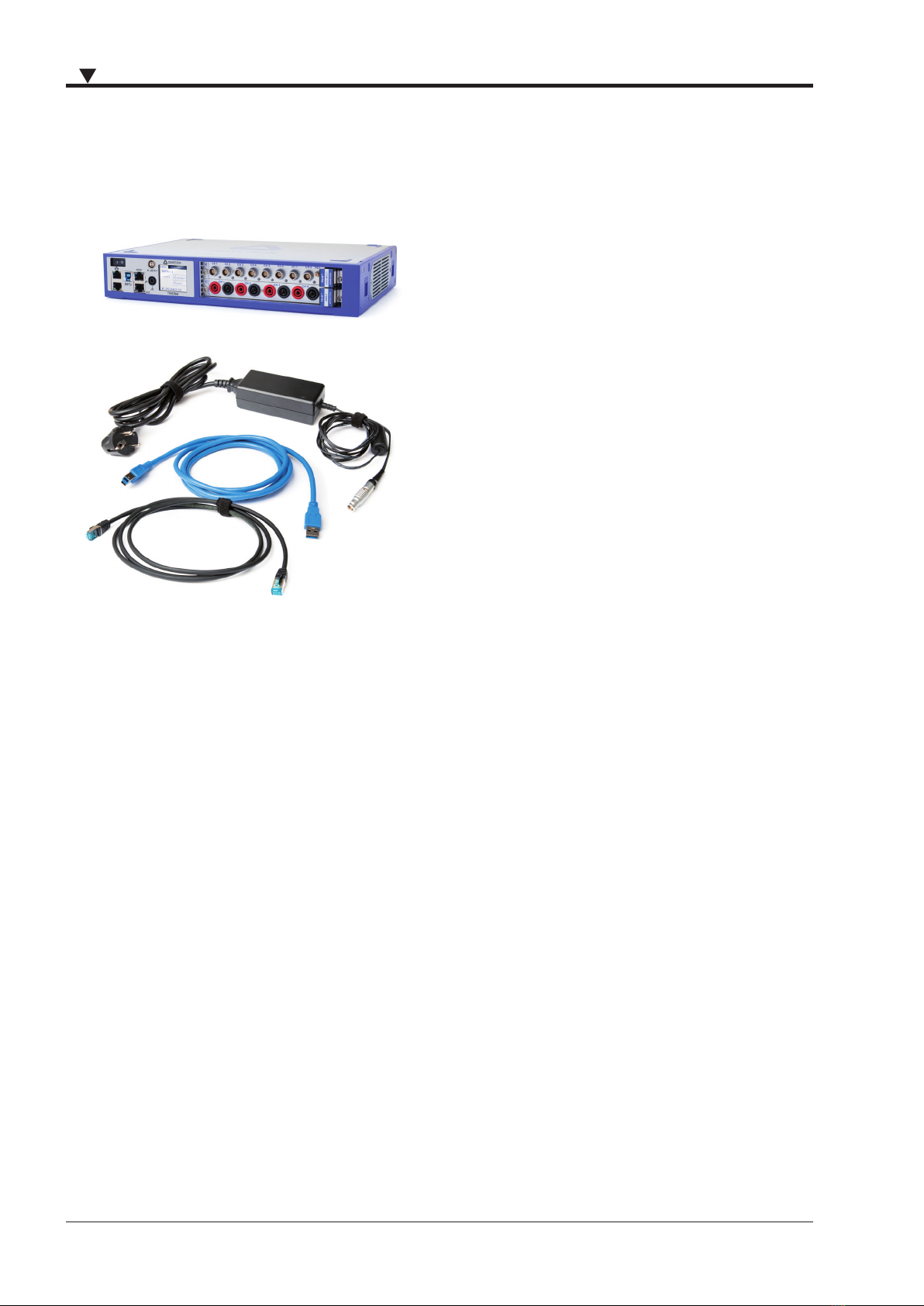
Scope of delivery...................................................4
General information..........................7
Environmental consideraons ...............................7
Problemac network stacks ..................................7
Warranty informaon ...........................................7
Legal informaon ..................................................7
Restricted rights legend ..................................... 7
Legal disclaimer .................................................. 7
Prinng history .....................................................8
Safety ..............................................9
Safety instrucons ................................................9
General safety instrucons ................................ 9
Electrical safety instrucons ............................ 10
Ambient safety noces ..................................... 10
Safety noces during operaon ....................... 11
Standards and norms ..........................................11
Typographic convenons.....................................11
Safety and warning noces .............................. 11
Noces ............................................................. 12
Symbols ............................................................ 12
System setup .................................13
Key facts .............................................................13
System specicaons ..........................................13
Dimensions* .......................................................14
Connecons and ports ........................................15
TRION(3) modules compability..........................16
TRION series modules overview ..........................17
Analog modules ............................................... 17
Digital modules ................................................ 17
Dedicated modules .......................................... 18
Touchscreen display ............................................18
Status tab ......................................................... 18
Info tab ............................................................. 19
Net tab ............................................................. 19
Reset IP ............................................................ 20
TRION-SYNC-BUS interface ..................................20
USB 3.0 interface connector ................................21
Gigabit Ethernet LAN connectors.........................21
Locking mechanism and release buon...............22
Fans ....................................................................22
Installing a TRION module...................................23
Power supply ......................................................24
Connecng TRIONet to laptop/PC .......................25
Install TRION package ....................................... 25
Connect TRIONet to laptop/PC via USB 3.0 or
Gigabit Ethernet ............................................... 26
Seng up your TRIONet with DEWETRON Ex-
plorer (stac IP, DHCP, node name) .................. 35
Installaon of OXYGEN measurement soware ...40
Seng up TRIONet in OXYGEN ............................42
Synchronizaon of mulple TRIONet units ..........44
Synchronizaon setup in OXYGEN .................... 44
TRION-SYNC-BUS .............................................. 44
Synchronizaon examples ................................ 44
Connect CPAD2/3 modules to TRIONet................45
Maintenance and service ................49
Service interval ...................................................49
Cleaning..............................................................49
Firmware upgrade...............................................49
Perform a rmware upgrade ............................ 49
Create USB drive for rmware upgrade ........... 51
Updang rmware les on exisng USB drive . 54
Perform a remote update w/o a USB drive ...... 56
Service and repairs..............................................58
Calibraon ..........................................................58
Support...............................................................59
Training...............................................................59
Troubleshooting..............................60
Certificate of conformity.................62

TABLE OF CONTENTS
6
Notes

General information
7
TRIONet • Technical reference • Prinng version 1.0.7 • October 15, 2021
General information
Environmental considerations
The following informaon refers to the environmental impact of the product and the product end-of-life handling.
Observe the following guidelines when recycling a DEWETRON system:
System and components recycling
The producon of these components has required the extracon and use of natural resources. The
substances contained in the system could be harmful to your health and to the environment if the
system is improperly handled at its end of life. Recycle this product in an appropriate way to avoid
an unnecessary polluon of the environment and to keep natural resources.
This symbol indicates that this system complies with the European Union’s requirements according
to Direcve 2002/96/EC on Waste of Electrical and Electronic Equipment (WEEE). Further informa-
on about recycling can be found on the DEWETRON website (www.dewetron.com).
Restricon of hazardous substances
This product has been classied as Monitoring and Control equipment, and is outside the scope of the 2011/65/EU
RoHS Direcve. This product is known to contain lead.
Problematic network stacks
Oen intrusive IT soware or network processes can interfere with the primary funcon of the DEWETRON system: to
record data. Therefore we recommend strongly against the installaon of IT/MIS soware and running their process-
es on any DEWETRON data acquision system, and cannot guarantee the performance of our systems if they are so
congured.
Warranty information
A copy of the specic warranty terms applicable to your DEWETRON product and replacement parts can be obtained
from your local sales and service oce.
Legal information
Restricted rights legend
Use Austrian law for duplicaon or disclosure.
DEWETRON GmbH
Parkring 4
8074 Grambach
Austria
TRION and OXYGEN are trademarks of DEWETRON GmbH.
Any other trademarks and registered trademarks are acknowledged to be the property of their owners.
Legal disclaimer
The informaon contained in this document is subject to change without noce.
DEWETRON GmbH (DEWETRON) shall not be liable for any errors contained in this document.
DEWETRON MAKES NO WARRANTIES OF ANY KIND WITH REGARD TO THIS DOCUMENT, WHETHER EXPRESS OR
IMPLIED. DEWETRON SPECIFICALLY DISCLAIMS THE IMPLIED WARRANTIES OF MERCHANTABILITY AND FITNESS FOR A

General information
8
PARTICULAR PURPOSE. DEWETRON shall not be liable for any direct, indirect, special, incidental, or consequenal dam-
ages, whether based on contract, tort, or any other legal theory, in connecon with the furnishing of this document or
the use of the informaon in this document.
Printing history
Refer to the page boom for prinng version.
Copyright © DEWETRON GmbH
This document contains informaon which is protected by copyright. All rights are reserved. Reproducon, adaptaon,
or translaon without prior wrien permission is prohibited, except as allowed under the copyright laws.

Safety
9
TRIONet • Technical reference • Prinng version 1.0.7 • October 15, 2021
Safety
Safety instructions
The following secon contains warning and safety instrucons that must be observed by the user. Faultless operaon
can only be guaranteed if these instrucons are observed.
General safety instructions
`Use this system under the terms of the specicaons only to avoid any possible danger. If the unit is used in a man-
ner not specied by the manufacturer the protecon can be impaired.
`Maintenance is to be executed by qualied sta only.
`DO NOT use the system if equipment covers or shields are removed. If you assume the system is damaged, have it
examined by authorized personnel only.
`Any other use than described above may damage your system and is aended with dangers such as short-circuits,
re or electric shocks.
`The whole system must not be changed, rebuilt or opened (except for changing TRION modules).
`Reinstall ller panels of unused TRION slots to guarantee proper cooling of the installed modules. The warranty is
void if the modules overheat due to missing ller panels.
`If you assume a more riskless use is not provided anymore, the system has to be rendered inoperave and should
be protected against inadvertent operaon. It is assumed that a more riskless operaon is not possible anymore, if
– the system is damaged obviously or causes strange noises.
– the system does not work anymore.
– the system has been exposed to long storage in adverse environmental.
– the system has been exposed to heavy shipment strain.
`The warranty is void if damages caused by disregarding this manual. For consequenal damages NO liability will be
assumed.
`The warranty is void if damages to property or persons caused by improper use or disregarding the safety instruc-
ons.
`Unauthorized changing or rebuilding the system is prohibited due to safety and permission reasons (CE).
Excepon: changing DAQP/PAD/HSI/TRION/TRION3 modules.
`Prevent using metal bare wires as there is a risk of short-circuit and re hazard.
`DO NOT use the system before, during or shortly aer a thunderstorm (risk of lightning and high energy overvolt-
age). An advanced range of applicaon under certain condions is allowed with therefore designed products only.
For details refer to the specicaons.
`Make sure that your hands, shoes, clothes and as well as the oor, the system or measuring leads, integrated cir-
cuits etc. are dry.
`Use measurement leads or measurement accessories aligned to the specicaon of the system only. Fire hazard in
case of overload.
`Do not disassemble the system. There is a high risk of geng a perilous electric shock. Capacitors sll might
charged, even the system has been removed from the power supply.
`The measuring systems are not designed for use at humans and animals.
`Contact a professional if you have doubts about the method of operaon, safety or the connecon of the system.
`Handle the product with care. Shocks, hits and dropping it even from an already lower level may damage your
system.
For exact values refer to the enclosed specicaons.

Safety
10
`Also consider the detailed technical reference manual as well as the security advices of the connected systems.
Electrical safety instructions
`With this product, only use the power cable delivered or dened for the host country.
`DO NOT connect or disconnect sensors, probes or test leads, as these parts are connected to a voltage supply unit.
`The system is grounded via a protecve conductor in the power supply cord. To avoid electric shocks, the protecve
conductor has to be connected with the ground of the power network. Before connecng the input or output con-
nectors of the system, make sure that there is a proper grounding to guarantee potenal free usage. For countries,
in which there is no proper grounding, refer to your local legally safety regulaons for safety use.
`DC systems: Every DC system has a grounding connected to the chassis (yellow/green safety banana plug).
`Note the characteriscs and indicators on the system to avoid re or electric shocks. Before connecng the system,
carefully read and understand the corresponding specicaons in the product manual.
`The inputs are not, unless otherwise noted (CATx idencaon), for connecng to the main circuits of category II, III
and IV. The measurement category can be adjusted depending on module conguraon.
`The power cord or the main power switch separates the system from the power supply. Do not block the power
cord or main switch, since it has to be accessible for the users.
`Any direct voltage output is protected with a fuse against short-circuits and reverse-polarity, but is NOT galvanically
isolated (except it is explicit marked on the system).
`Supply overvoltage category is II.
`The system must be connected and operated to an earthed wall socket at the AC mains power supply only (except
for DC systems).
`DO NOT touch any exposed connectors or components if they are live wired. The use of metal bare wires is not
allowed. There is a risk of short-circuits and re hazard.
`The assembly of the system is equivalent to protecon class I. For power supply, only the correct power socket of
the public power supply must be used, except the system is DC powered.
`Be careful with voltages >25 VAC or >35 VDC. These voltages are already high enough in order to get a perilous electric
shock by touching the wiring.
`Unless otherwise stated, the maximum input voltage for measuring cards is 70 VDC and 46.7 VPEAK
`The electrical installaons and equipments in industrial facilies must be observed by the security regulaons and
insurance instuons.
Ambient safety notices
`This product is intended for use in industrial locaons. As a result, this product may cause interference if used in
residenal areas. Such use must be avoided unless the user takes special measures to reduce electromagnec emis-
sions to prevent interferences to the recepon of radio and television broadcasts.
`Do not switch on the system aer transporng it from a cold into a warm room and vice versa. The thereby created
condensaon may damage your system. Acclimase the system unpowered to room temperature.
`Any use in wet rooms, outdoors or in adverse environmental condion is not allowed. Adverse environmental condi-
ons are:
– Moisture or high humidity
– Dust, ammable gases, fumes or dissolver
– Thunderstorm or thunderstorm condions (except assembly PNA)
– Electrostac elds etc.
`DO NOT use the system in rooms with ammable gases, fumes or dust or in adverse environmental condions.
`Direct exposure of any DEWETRON product to strong sunlight or other heat radiaon shall be prevented, as this

Safety
11
TRIONet • Technical reference • Prinng version 1.0.7 • October 15, 2021
could excessively heat up the product and lead to permanent damage of the product.
`The use of the measuring system in schools and other training facilies must be observed by skilled personnel.
Safety notices during operation
`During the use of the system, it might be possible to access another parts of a more comprehensive system. Read
and follow the safety instrucons provided in the manuals of all other components regarding warning and security
advices for using the system.
`The product heats during operaon. Make sure there is adequate venlaon. Venlaon slots must not covered.
Only fuses of the specied type and nominal current may be used. The use of patched fuses is prohibited.
Standards and norms
This product has le the factory in safety-related awless and proper condion.
In order to maintain this condion and guarantee safety use, the user has to consider the security advices and warn-
ings in this manual.
EN 61326-3-1:2008
IEC 61326-1 applies to this part of IEC 61326 but is limited to systems and equipment for industrial applicaons intend-
ed to perform safety funcons as dened in IEC 61508 with SIL 1-3.
The electromagnec environments encompassed by this product family standard are industrial, both indoor and out-
door, as described for industrial locaons in IEC 61000-6-2 or dened in 3.7 of IEC 61326-1.
Equipment and systems intended for use in other electromagnec environments, for example, in the process industry
or in environments with potenally explosive atmospheres, are excluded from the scope of this product family stan-
dard, IEC 61326-3-1.
Devices and systems according to IEC 61508 or IEC 61511 which are considered as “operaonally welltried”, are exclud-
ed from the scope of IEC 61326-3-1.
Fire-alarm and safety-alarm systems, intended for protecon of buildings, are excluded from the scope of
IEC 61326-3-1.
Typographic conventions
Safety and warning notices
WARNING
!
Indicates a hazardous situaon that, if not avoided, could result in death or serious injury.
CAUTION
!
Indicates a hazardous situaon that, if not avoided, could result in minor or moderate injury.

Safety
12
Notices
NOTICE
This text indicates situaons or operaon errors which could result in property damage or data loss.
INFORMATION
This text indicates important informaon or operang instrucons. Not observing these instrucons
could inhibit or impede you from successfully compleng the tasks described in this documentaon.
Symbols
!
Denotes a warning that alerts you to take precauons to avoid injury. When this symbol is shown on
the product, refer to the technical reference manual (ISO 7000-4034; 2004-01).
Indicates hazardous voltages.
Observe precauons for handling electrostac sensive devices.
Indicates the chassis terminal (IEC 60417-5020; 2002-10).
Direct current (IEC 60417-5031; 2002-10)
Alternate current (IEC 60417-5032; 2002-10)
Both direct and alternang current (IEC 60417-5033; 2002-10)
3Three-phase alternang current (IEC 60417-5032-1; 2002-10)
Protecve conductor terminal (IEC 60417-5019; 2006-08)
Equipment protected throughout by double insulaon or reinforced insulaon
(IEC 60417-5172; 2003-02)
On (power) (IEC 60417-5007; 2002-10)
O (power) (IEC 60417-5008; 2002-10)

SyStem SetuP
13
TRIONet • Technical reference • Prinng version 1.0.7 • October 15, 2021
System setup
Key facts
`Small, distributable data acquision front-end
`2 slots for user exchangeable TRION series modules
`USB 3.0 or Gigabit Ethernet connecon to notebook or
desktop
`Touchscreen on front panel
`4 slots for TRION/TRION3 acquision series modules
System specifications
TRIONet
Data acquision 2 slots for TRION acquision modules1)
Quasi stac channel expansion CPAD via TRION-CAN or TRION-MULTI (no EPAD)
LAN 2 x 10/100/1000BASE-TX Gigabit Ethernet
LAN conguraon DHCP or Stac IP
USB USB 2.0; USB 3.0
Synchronizaon TRION-SYNC-Bus up to 100 m between nodes
System bandwidth 90 MB/s with one connected TRIONet (up to 50 MB/s with more than one)
Display Status display with touchscreen
Cooling 2 temperature controlled ultra silent fans
Isolated power supply
– Rated input voltage
– Power consumpon
– External power supply (incl.)
10 to 32 VDC (9 to 36 VDC)
15 W without modules, totally equipped max. 55 W
100 to 240 VAC ~50 to 60 Hz / 65 W
Operang temperature -20 °C to +50 °C (with pre-warmed unit)
Storage temperature -20 °C to +70 °C
Humidity (operang) 10 % to 90 %, non condensing
5 % to 95 % rel. humidity
Altude (max.) 3000 m (9840 )
Vibraon test (EN 60068-2-6)
Shape
Frequency range
Acceleraon
Sweep rate
Duraon test in 3 direcons
Sine
10–150 Hz
2 g
1 oct./min.
20 cycles
Tab. 1: System specicaons TRIONet

SyStem SetuP
14
TRIONet
Shocktests; EN 60068-2-27
Pulse form
Acceleraon amplitude
Duraon
Direcon
Half-sine
30 g
11 ms
Test in 3 axis, 3 shocks in each axis and direcon
Random vibraon test; EN 60721-3-2; Class 2M3
Shape
Frequency range
Power spectral density
Duraon
Random
10–200 Hz
1 m/s²/Hz
30 min/axis
Dimensions (W x D x H) Approx. 320 x 205 x 55 mm (12.6 x 8 x 2.2 in.)
Weight Typ. 1.9 kg (4.2 lbs) without modules
Tab. 1: System specicaons TRIONet
1) TRION3 modules are not supported.
Dimensions*
320,4
206
54,7
1,51,
2
*) Dimensions in mm (1 inch = 25.4 mm)
Fig. 2: Dimensions TRIONet

SyStem SetuP
15
TRIONet • Technical reference • Prinng version 1.0.7 • October 15, 2021
Connections and ports
3
4
5
1
6
2
78
Fig. 3: TRIONet front view
1010
9
11
9
Fig. 4: TRIONet right side view
1. USB 3.0 interface connector (Type B)
2. Power supply input connector (LEMO EGG.1B.302)
3. Power-on switch
4. Gigabit Ethernet interface
5. TRION-SYNC-BUS interface
6. Chassis terminal
7. Touchscreen display
8. TRION series module slots
9. Locking mechanism for stacking units
10. Release buon for locking mechanism
11. Fans
INFORMATION
The amount and locaon of the connectors might vary from system to system and depend on the sys-
tem conguraon.

SyStem SetuP
16
No. Element Descripon
1. USB interface connectors The TRIONet is equipped with a USB 3.0 interface (type B) to connect to a laptop
or PC. For details see USB 3.0 interface connector on page 21.
2. Power supply input con-
nector
LEMO EGG.1B.302
+-
Input range 11...32 VDC (external AC/DC power supply included). For
details see Power supply on page 24.
3. Power-on switch The power-on switch is used to switch on the system.
4. Ethernet LAN connector The TRIONet supports Gigabit Ethernet interface ports for connecng the device
with a laptop/PC or daisy-chaining mulple units with standard RJ45 connector.
For details see Gigabit Ethernet LAN connectors on page 21.
5. TRION SYNC-BUS The TRIONet is equipped with two addional TRION-SYNC-BUS interface connec-
tors for daisy-chaining mulple TRIONet units. For details see TRION-SYNC-BUS
interface on page 20.
6. Chassis terminal For some kind of measurements, it is necessary to provide the sys-
tem with an addional ground connecon.
7. Touchscreen The integrated touch screen display of the TRIONet shows all relevant informa-
on straight on the device. For details see Touchscreen display on page 18.
8. TRION series module slots Slots for 2x TRION series modules.
INFORMATION TRION3 series modules are not supported. For details see TRI-
ON(3) modules compability on page 16.
9. Locking mechanism The TRIONet comes with a niy locking mechanism if you want to stack your
units. For details see Locking mechanism and release buon on page 22.
10. Release buon Release buon for locking mechanism. For details see Locking mechanism and
release buon on page 22.
11. Fans 2 temperature-controlled ultra silent fans are installed on the right side of the
TRIONet. For details see Fans on page 22.
Tab. 2: Connecons and ports TRIONet
TRION(3) modules compatibility
Supported modules Not supported modules
TRION-2402-MULTI TRION-VGPS TRION-FLEXRAY
TRION-1620-ACC/LV TRION-TIMING TRION-MIL1553
TRION-2402-V TRION-CAN TRION-MA4
TRION-1603-LV TRION-1820-POWER TRION-1810-HV-8
TRION-2402-dSTG TRION-PSU-15W TRION-1628-AO
TRION-2402-dACC - TRION-ARINC429
TRION-1802/1600-dLV-32 - TRION3-1810M-POWER-4
TRION-CNT - TRION3-1810-SUB-8
TRION-DI-48 - TRION3-18xx-MULTI
TRION-BASE - TRION-EtherCAT-1-SLAVE
Tab. 3: Supported and not supported TRION modules

SyStem SetuP
17
TRIONet • Technical reference • Prinng version 1.0.7 • October 15, 2021
INFORMATION
TRION3 series modules are not supported.
TRION series modules overview
Analog modules
ANALOG modules Channels Sample rate
per channel Resoluon Isolaon Connector
type
TRION-2402-MULTI
V
100 4 or 8 200 kS/s 24 bit yes D-SUB,
LEMO 0B
TRION-1620-ACC V
100 00 6 2 MS/s 24 bit
>1 MS/s: 16 bit yes LEMO 1B,
BNC
TRION-1620-LV V
100 6 2 MS/s 24 bit
>1 MS/s: 16 bit yes LEMO 1B,
BNC
TRION-2402-V1) V
1000 4 or 8 200 kS/s 24 bit yes Safety
banana
TRION-1603-LV V
100 6 250 kS/s 16 bit yes BNC,
LEMO 1B
TRION-2402-dSTG1)
V
10 6–8 200 kS/s 24 bit no
LEMO 1B,
LEMO 0B,
D-SUB,
RJ-45
TRION-2402-dACC
V
100 00 6–8 200 kS/s 24 bit no SMB, BNC
TRION-1802-dLV V
1000 00 MSI
CB16 16 or 32 200 kS/s
100 kS/s
18 bit
24 bit no D-SUB
TRION-1600-dLV V
1000 00 MSI
CB16 16 or 32 20 kS/s 16 bit no D-SUB
Tab. 4: TRION/TRION3 analog modules
1) Some versions of this module occupy 2 TRION slots.
2) CAT III 1000 V only applicable for 1000 V inputs; SUB-600V has CAT II 600 V / CAT III 300 V
Digital modules
DIGITAL modules Channels Sample rate
per channel Resoluon Isolaon Features
TRION-CNT 00 6 800 kS/s 80 MHz yes 6 channel ad-
vanced counter
TRION-DI-48 48 2 MS/s 500 nsec yes 48 highspeed
digital IN
TRION-BASE IRIG
00 - 2 MS/s 80 MHz no Basic IO card with
simple IRIG sync
and 2 counter
Tab. 5: TRION digital modules

SyStem SetuP
18
DIGITAL modules Channels Sample rate
per channel Resoluon Isolaon Features
TRION-VGPS-V3 IRIG
100 Hz
00 PTP - 2 MS/s 0.01 km/h
<10 cm no
100 Hz GNSS
receiver for
automove appli-
caons
TRION-TIMING-V3 IRIG
10 Hz
00 PTP - 2 MS/s 12.5 nsec no Applies precision
absolute me to
measured data
TRION-CAN 41 MBit - yes D-SUB
Tab. 5: TRION digital modules
Dedicated modules
DEDICATED modules 00101001010001 Channels Sample rate
per channel Resoluon Isolaon Features
TRION-CAN 41 MBit - yes D-SUB
TRION-1820-POWER V
1000 8 (4 U/4 I) 2 MS/s ≥18 bit yes Safety banana,
D-SUB
Tab. 6: TRION dedicated modules
INFORMATION
The TRION-TIMING module has to be installed in the STAR-slot for TRION modules. For further informa-
on regarding the STAR-slot for TRION modules refer to the TRION series modules technical reference
manual.
Touchscreen display
The integrated touchscreen display of the TRIONet shows all relevant informaon straight on the device. To switch
between the tabs, simply touch the display.
The following informaon is shown on the display:
Status tab
The status tab follows the boot screen animaon and shows informaon about TRION hardware, sync status, IP ad-
dress and transfer/recording status. To switch between tabs just tab anywhere on the screen.
Status
TRIONet Node 1
Sync: Slave
IP: 192.168.0.150
Info Net
2 1603-LV
1 2402-MULTI
Highlighted tab 'Status'
Name of your TRIONet node
Sync status
Transfer/Recording status Installed TRION modules
IP address
Connected
Fig. 5: Status tab
`Highlighted tab 'Status'
The 'status' tab is the main screen aer the device booted correctly.

SyStem SetuP
19
TRIONet • Technical reference • Prinng version 1.0.7 • October 15, 2021
`Name of your TRIONet node
The name of the TRIONet node is shown here and can be changed with the DEWETRON Explorer. For more informa-
on see Seng up your TRIONet with DEWETRON Explorer (stac IP, DHCP, node name) on page 35.
`Sync status
The actual sync status of the TRIONet. The following statuses are available:
– None: Standalone device
– Sync: Master: The device is set as master
– Sync: Slave: The device is set as 'slave-end' or 'slave-mid'
`Transfer/recording status: Shows the actual transfer/recording status. Following statuses are available:
– None: The device is not connected
– Connected: The device is connected to the soware (OXYGEN, DS7 etc.)
– Acve: Measurement acve
– Record: Measurement acve and recording
`IP-adress: Shows the current IP address. The IP address can be set to stac or DHCP.
For more informaon see chapter Seng up your TRIONet with DEWETRON Explorer (stac IP, DHCP, node name) on
page 35.
Info tab
The 'Info' display tab shows some internal health parameters. This is a live display with an update rate of approx. 1 s. In
case of support have your rmware/server revision number ready for further instrucons. To switch between tabs just
tab anywhere on the screen.
Status
Power Consum.: 15.3 W
System Temp.: 43.5 °C
Env. Temp.: 24.2 °C
Firmware: 2.4.2.0
Server: 2.4.30645
S/N: CXXXXXXX
Info Net
Highlighted tab 'Info'
Power consumpon
Environmental temperature
System temperature
Firmware revision
Server revision
Serial number
Fig. 6: Info tab
Net tab
The 'Net' display tab shows the network sengs of the TRIONet device itself and the client if connected. In this tab
there is also the possibility of reseng the IP address of the TRIONet.
For more informaon on how to change IP address and subnet mask see Seng up your TRIONet with DEWETRON
Explorer (stac IP, DHCP, node name) on page 35.
Details regarding ZeroConf IP address can be found in ZeroConf (Zero Conguraon Networking) and link-local address-
es on page 27 .
Status
Addr.: 169.254.11.72
Mask: 255.255.0.0
Client: 169.254.118.151
ZConf: 169.254.11.72
Info Net
Highlighted tab 'Net'
Current IP address
Subnet mask
IP address of connected client
ZeroCong IP address
Reset IP address RESET IP
Fig. 7: Net tab

SyStem SetuP
20
Reset IP
If 'RESET IP' is pressed, the following screen will display:
Reset IP address to
Default DHCP
CANCEL
Fig. 8: Reset IP
`Default: This will reset the IP address of the TRIONet to default 192.168.0.150.
`DHCP: Choose 'DHCP' if the TRIONet should be implemented in a proprietary, already exisng LAN with a DHCP
server up and running. The DHCP lookup may take a few minutes. If the DHCP lookup failed, the TRIONet will switch
automacally to a fallback address called 'Link-Local IP address'.
Refer to ZeroConf (Zero Conguraon Networking) and link-local addresses on page 27 for more details.
TRION-SYNC-BUS interface
The TRIONet is equipped with two addional TRION™-SYNC-BUS interface connectors for daisy-chaining mulple TRIO-
Net units. SYNC cables are not included an have to be ordered separately.
SYNC OUT SYNC IN
RED (stable) Clock detected Clock detected / Receiving clock
GREEN (stable) Acquision running Acquision running
Tab. 7: LED indicaon
Depending on the usage of the SYNC I/O (input or output) the LED indicates if the system clock is available or received
correctly from another system. The green LED indicates that the acquision is running. If the acquision stops the LED
will be o.
Oponal cables
`TN-DCHAIN-SET-0.2
A set of two cables (data and sync) for daisy-chaining two TRIONet units in stacked conguraon, cable length ap-
prox. 0.2 m. Other cables on request.
NOTICE
The total length of the SYNC cable between TRIONet units must not exceed 100 m (328 ), otherwise
the data will not synchronize.
Other manuals for TRIONet
1
Table of contents
Other Dewetron Analytical Instrument manuals
Popular Analytical Instrument manuals by other brands

General Pipe Cleaners
General Pipe Cleaners Gen-Eye Prism 2.0 operating instructions

Fluke
Fluke FI-3000 FiberInspector Pro Getting started guide

TEGRAS Concept
TEGRAS Concept Grasmeter user manual

VOLTCRAFT
VOLTCRAFT BS-24 manual

LaserLiner
LaserLiner HD MicroCamera operating instructions

Covaris
Covaris S220 user manual