Dexing NDS3228A User manual

NDS3228A 8 in 1 MPEG2/H.264 SD Encoder
User’s Manual
SW Version: 2.14
HW version: 0.3
Chengdu Dexin Digital Technology Co., Ltd.

DIRECTORY
Chapter 1 Product Introduction.................................................................................................................. 1
1.1 Outline .................................................................................................................................................1
1.2 Main Features ...................................................................................................................................... 1
1.3 Specifications....................................................................................................................................... 1
1.4 Principle Chart.....................................................................................................................................2
1.5 Appearance and Illustration ................................................................................................................. 3
Chapter 2 Installation Guide......................................................................................................................5
2.1 Acquisition Check................................................................................................................................ 5
2.2 Installation Preparation........................................................................................................................5
2.3 Wire’s Connection................................................................................................................................7
2.4 Signal Cable Connection......................................................................................................................7
Chapter 3 Operation................................................................................................................................. 11
3.1 Initializing.......................................................................................................................................... 11
3.2 General Setting .................................................................................................................................. 11
Chapter 4 NMS Operation (Optional)..................................................................................................... 24
4.1 Installation ......................................................................................................................................... 24
4.2 Software Operation............................................................................................................................24
4.3 NDS3228A 8 in 1 MPEG-2 H.264 SD Encoder Operation ...............................................................30
4.4 Other Settings ....................................................................................................................................42
Chapter 5 WEB NMS Operation (Optional)............................................................................................46
5.1 login...................................................................................................................................................46
5.2 Operation ...........................................................................................................................................47
Chapter 6 Troubleshooting.......................................................................................................................54
Chapter 7 Packing list..............................................................................................................................55

NDS3228A 8 in 1 MPEG-2 H.264 SD Encoder User’s Manual
1/ 57
Chapter 1 Product Introduction
1.1 Outline
The DEXIN NDS3228A series 8-in-1 MPEG-2/H.264 SD Encoders are our
professional SD audio & video encoding and multiplexing device with
powerful functionality. It has 8 independent channels of unbalanced audio &
CVBS video input interfaces or SD-SDI input interfaces. It supports MPEG-2
and H.264 video encoding and MPEG-1 Audio layer 2, LC-AAC and HE-AAC
audio encoding. Its each channel can reach an ultra low bit-rate.
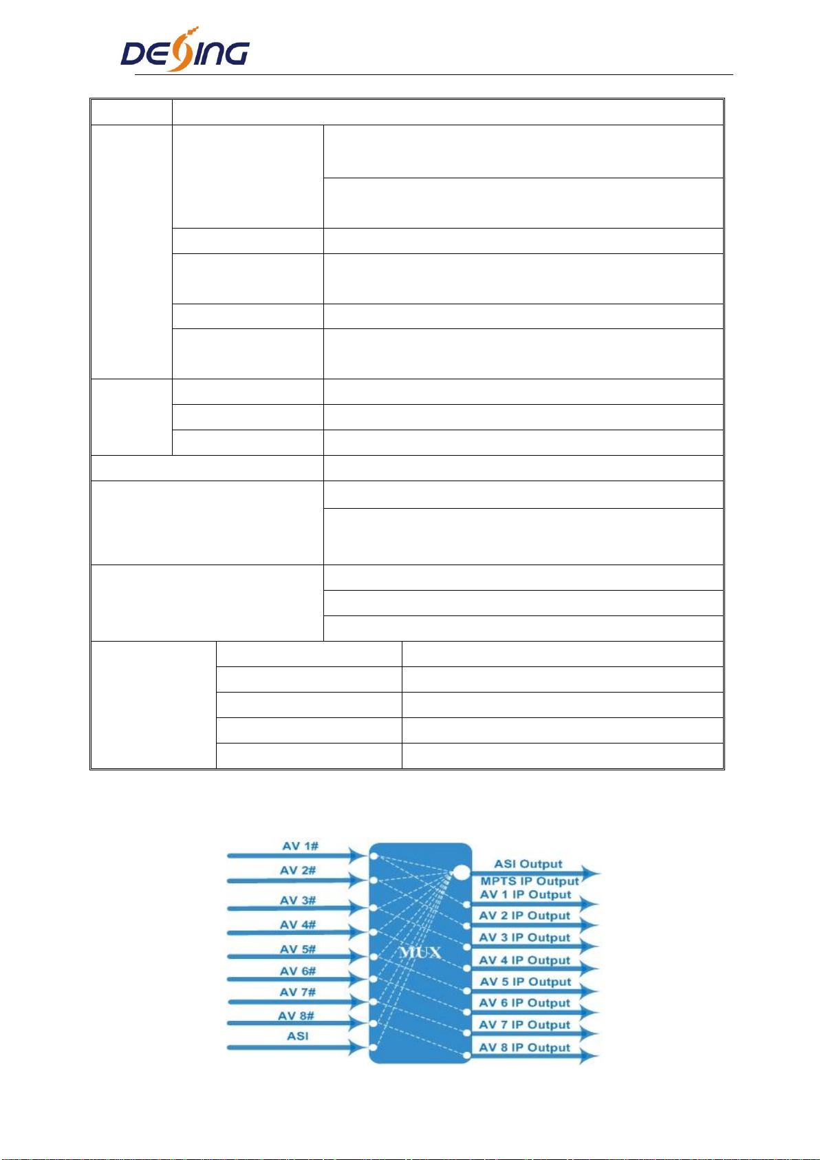
Moreover, it has an ASI input and can multiplex the input TS with the 8
encoded SPTS to generate a MPTS output.
1.2 Main Features
Support 8 AV (CVBS or SDI optional),1 ASI Input
H.264 and Mpeg2 video encoding
MPEG1 Audio Layer 2, LC-AAC and HE-AAC (V2) audio encoding
Support PSI/SI editing and inserting
Supports VBR/CBR video encoding
Supports ultra low bit rate encoding
Applicable for one Seg/ISDB-T utilization
Supports MPTS or 8 SPTS UDP IP Output
Supports IP null packet filter
Real-time output bit-rate monitoring
LCD / keyboard and NMS operation
Update device through NMS port(Web or SNMP)
1.3 Specifications
Input
8 CVBS, BNC interface
NDS3228A
8 pairs of unbalanced stereo audio, BNC interface
V/A: 8xSD-SDI input with embedded audio
NDS3228A-D
NDS3228A 8 in 1 MPEG-2 H.264 SD Encoder User’s Manual
2 / 55
1 ASI input, BNC interface
Video
Resolution
PAL:720*576/352*288/320*240/320*180/176*144/
160*120/160*90@50Hz
NTSC: 720*480/352*288/320*240/320*180/176*144/
160*120/160*[email protected]
Encoding
MPEG-2 / H.264
Bit-rate
0.25~15Mbps for H.264 encoding
0.5~15Mbps for MPEG-2 encoding
Rate Control
CBR/VBR
Advanced
Pretreatment
De-interlacing, Noise Reduction, Sharpening
Audio
Encoding
MPEG1 Audio Layer 2, LC-AAC, HE-AAC V2
Sampling rate
48KHz
Bit-rate
32Kb/s~384Kb/s (each channel)
Multiplexing
1 ASI input multiplexed with local 8 channels of TS
Stream output
2*ASI output, BNC interface
MPTS / 8 SPTS over UDP, 10/100Base-T Ethernet
interface (UDP unicast / multicast)
System function
LCD/keyboard operating, NMS supporting
Chinese-English control interface
Ethernet software & hardware upgrade
Miscellaneous
Dimension (W× L× H)
482mm×455mm×44mm
Approx weight
4kg
Temperature
0~45℃(work), -20~80℃(Storage)
Power
AC 100V-220V±10%, 50/60Hz
Consumption
25W
1.4 Principle Chart

NDS3228A 8 in 1 MPEG-2 H.264 SD Encoder User’s Manual
3 / 55
1.5 Appearance and Illustration
Front Panel Illustration:
Indicate area: All indicators will light on when the device is on the current working state.
1
LCD Screen
2
Indicators
Power Indicator
TS In: Input Lock Indicator
CH1-CH8: When the program has been multiplexed, the
indicator will be on.
3
UP/ DOWN, LEFT/RIGHT Keys
4
Enter Key
5
Menu Key
6
Lock Key
Rear Panel Illustration (CVBS input)
2
3
4

NDS3228A 8 in 1 MPEG-2 H.264 SD Encoder User’s Manual
4 / 55
1
8 * CVBS Input Ports
2
CVBS Input Serial Number from 1 to 8
3
Video Input Port
4
Audio Input Port (Left & Right Channels)
5
ASI Input Port
6
2 * ASI Output Ports
7
Data Port (for IP Signal Output)
8
NMS (Network Management Port)
9
Power Switch
10
Fuse
11
Power Socket
12
Grounding Pole
Rear Panel Illustration (SDI input)
①②③④⑤⑥⑦ ⑧⑨
1
8 * SDI Input Ports
2
ASI Input Port
3
2 * ASI Output Ports
4
Data Port (for IP Signal Output)
5
NMS (Network Management Port)
6
Power Switch
7
Fuse
8
Power Socket
9
Grounding Pole

NDS3228A 8 in 1 MPEG-2 H.264 SD Encoder User’s Manual
5 / 55
Chapter 2 Installation Guide
2.1 Acquisition Check
When users open the package of the device, it is necessary to check items according to packing
list. Normally it should include the following items:
NDS3228A 8 in 1 MPEG-2/H.264 SD Encoder
User’s Manual
CVBS/SDI Cable
ASI Cable
Power Cord
If any item is missing or mismatching with the list above, please contact local dealer.
2.2 Installation Preparation
When users install device, please follow the below steps. The details of installation will be
described at the rest part of this chapter. Users can also refer rear panel chart during the
installation.
The main content of this chapter including:
Checking the possible device missing or damage during the transportation
Preparing relevant environment for installation
Installing Encoder
Connecting signal cables
Connecting communication port (if it is necessary)
2.2.1 Device’s Installation Flow Chart is Illustrated as following:
Connecting
Grouding
Wire and
Power
Cord
Acquisition
Check Fixing
Device Setting
Parameter Running
Device
Connecting
Signal Wire
2.2.2 Environment Requirement

NDS3228A 8 in 1 MPEG-2 H.264 SD Encoder User’s Manual
6 / 55
Item
Requirement
Machine Hall Space
When user installs machine frame array in one machine hall, the
distance between 2 rows of machine frames should be 1.2~1.5m
and the distance against wall should be no less than 0.8m.
Machine Hall Floor
Electric Isolation, Dust Free
Volume resistivity of ground anti-static material:
1X10⁷~1X10¹⁰,Grounding current limiting resistance: 1M
(Floor bearing should be greater than 450Kg/㎡)
Environment
Temperature
5~40℃(sustainable ),0~45℃(short time),
installing air-conditioning is recommended
Relative Temperature
20%~80% sustainable 10%~90% short time
Pressure
86~105KPa
Door & Window
Installing rubber strip for sealing door-gaps and dual level
glasses for window
Wall
It can be covered with wallpaper, or brightness less paint.
Fire Protection
Fire alarm system and extinguisher
Power
Requiring device power, air-conditioning power and lighting
power are independent to each other. Device power requires AC
power 220V 50Hz. Please carefully check before running.
2.2.3 Grounding Requirement
All function modules’ good grounding designs are the basis of reliability and stability of
devices. Also, they are the most important guarantee of lightning arresting and interference
rejection. Therefore, the system must follow this rule.
Coaxial cable’s outer conductor and isolation layer should keep proper electric conducting
with the metal housing of device.
Grounding conductor must adopt copper conductor in order to reduce high frequency
impedance, and the grounding wire must be as thick and short as possible.
Users should make sure the 2 ends of grounding wire well electric conducted and be
antirust.
It is prohibited to use any other device as part of grounding electric circuit
The area of the conduction between grounding wire and device’s frame should be no less
than 25mm2.

NDS3228A 8 in 1 MPEG-2 H.264 SD Encoder User’s Manual
7 / 55
2.2.4 Frame Grounding
All the machine frames should be connected with protective copper strip. The grounding wire
should be as short as possible and avoid circling. The area of the conduction between
grounding wire and grounding strip should be no less than 25mm2.
2.2.5 Device Grounding
Connecting the device’s grounding rod to frame’s grounding pole with copper wire.
2.3 Wire’s Connection
The grounding wire conductive screw is located at the right end of rear panel, and the power
switch, fuse, power supply socket is just beside ,whose order goes like this, power switch is on
the left ,power supply socket is on the right and the fuse is just between them.
Connecting Power Cord
User can insert one end into power supply socket, while insert the other end to AC power.
Connecting Grounding Wire
When the device solely connects to protective ground, it should adopt independent way,
say, share the same ground with other devices. When the device adopts united way, the
grounding resistance should be smaller than 1Ω.
Caution:
Before connecting power cord to NDS3228A 8 in 1 MPEG-2 H.264 SD Encoder, user
should set the power switch to “OFF”.
2.4 Signal Cable Connection
The signal connections include the connection of input signal cable and the connection of
output signal cable. The details are as follows:
2.4.1 Unbalanced audio and CVBS video input cable illustration:

NDS3228A 8 in 1 MPEG-2 H.264 SD Encoder User’s Manual
8 / 55
2.4.2 ASI output cable illustration:
2.4.3 Network Cable illustration (CAT5):
2.4.4 Unbalanced audio and CVBS video input connection
User can firstly find the CVBS input connector on the device according to the connector mark
described on the rear panel illustration, and then connect the analog CVBS video and
unbalanced audio cables (in the accessories). One end is connected to the signal source
equipment while the other end to the encoder’s CVBS input port. The encoder’s Analog
Composite Video input port and its connection are illustrated as follows:

NDS3228A 8 in 1 MPEG-2 H.264 SD Encoder User’s Manual
9 / 55
2.4.5 SDI video input connection
User can find the SDI input connector on the device according to the connector mark described
on the rear panel illustration, and then connect the analog SDI video. One end is connected to
the signal source equipment while the other end to the encoder’s SDI input port. The encoder’s
Analog Composite Video input port and its connection are illustrated as follows:
2.4.6 ASI output interface connection
User can firstly find the ASI output interface on the device according to the connector mark
described on the rear panel illustration, and then connect the ASI cable (in the accessories). One
end is connected to the encoder’s ASI out connector (ASI1, ASI2) while the other end to the TS
stream multiplexer or modulator’s ASI input port. The encoder’s ASI output interface and its
connection are illustrated as follow:
2.4.7 IP Output Interface connection
Users can firstly find the DATA interface on the device according to the connector mark
described on the rear panel illustration, and then connect the network (CAT5). One end of the
network cable is connected to the encoder’s DATA output connector, while the other end to the
TS stream multiplexer IP input port or other device which can input IP signal. The encoder’s
DATA connection is illustrated as follows:

NDS3228A 8 in 1 MPEG-2 H.264 SD Encoder User’s Manual
10 / 55
2.4.8 NMS Connection
Users can firstly find the NMS interface on the device according to the connector mark
described on the rear panel illustration, and then connect the network (CAT5). One end of the
network cable is connected to the encoder’s NMS connecter, while the other end to the
computer or the PC. The encoder’s NMS connection is illustrated as follows:

NDS3228A 8 in 1 MPEG-2 H.264 SD Encoder User’s Manual
11 / 55
Chapter 3 Operation
NDS3228A 8 in 1 MPEG-2/H.264 SD Encoder’s front panel is user operating interface. Before
operating, user can decide whether directly use the default setting or customize the input and
output parameters setting. The detail operations go as follows:
Keyboard Function Description:
ENTER: Activating the parameters which need modifications, or confirming the change after
modification.
MENU: To cancel presently entered value, resume previous setting and return to previous
menu.
LEFT/RIGHT: To move the ―►‖ to choose or set the parameters.
UP/DOWN: To modify activated parameter or page up/down when parameter is inactivated.
LOCK: To Lock the screen / cancel the lock state. After pressing lock key, the system will
question the users to save present setting or not. If not, the LCD will display the current
configuration state.
At the ―Factory Configuration‖ page, user can press ―ENTER‖ key to restore the factory
default configuration.
3.1 Initializing
After powering on the device,it will take a few seconds to initialize the system, and then the
LCD will show the device name and output real-time bit-rate in the first row, while the 8
channels’ respective serial number and input real-time encoding bit-rate in the second row in
turn. It shows as below:
8 in 1 Encoder 9.720 Mbps
1P 02.94M 2P 02.73M 3P 02.92M 4P 02.90M
3.2 General Setting
By pressing LOCK key, users can enter in the main menu and set the input and output
NDS3228A 8 in 1 MPEG-2 H.264 SD Encoder User’s Manual
12 / 55
parameters in the following editing interfaces, the LCD will display the following pages:
►1 Input Setting 2 ASI Setting
3 Output Setting 4 Network Setting
►5 Saving Config 6 Loading Config
7 Version (SNMP/Web) 8 Language
The option with ―►‖ is the current selection, users can press the ENTER key to enter the
specified submenu to modify the device parameter.
3.2.1 Input Setting
Under this menu, users can enter the corresponding encoding channel to set the relevant audio
and video input parameters, and select programs to multiplex. The LCD will display 8
submenus which from Encoding Channel 1 to Encoding Channel 8. The setting principle is the
same for Encoding Channel 1-8, so here this manual just takes one channel as the example to
explain. After pressing the enter key, the LCD will display the following pages:
►1.1 Encoder 1 1.2 Encoder 2
1.3 Encoder 3 1.4 Encoder 4
►1.5 Encoder 5 1.6 Encoder 6
1.7 Encoder 7 1.8 Encoder 8
After users enter the submenu, the interface will turn into the following pages, and then users
can enter the corresponding interface to modify the parameters.
►1.1.1 Video 1.1.2 Audio
1.1.3 System 1.1.4 PG Muxer
►1.1.1 Video 1.1.2 Audio
1.1.3 System 1.1.4 PG Muxer
3.2.1.1 Video Setting

NDS3228A 8 in 1 MPEG-2 H.264 SD Encoder User’s Manual
13 / 55
►1.1.1.1 Input 1.1.1.2 Brightness
1.1.1.3 Contrast 1.1.1.4 Saturation
►1.1.1.5 Hue 1.1.1.6 Aspect Rati
1.1.1.7 Coding Type 1.1.1.8 Resolution
►1.1.1.9 Bitrate Mode 1.1.1.A Bit Rate
1.1.1.B Max Bit Rate 1.1.1.C Min Bit Rate
►1.1.1.D GOP Struct
Input
This is for user to check the input port type and it is read-only. It will identify the input port
type automatically.
At this interface, by pressing ENTER again, users can select the input format, which includes 8
options. Pressing 1.1.1.1, the operation interface will turn up as following page:
NOTE: Below explanations are applied in this entire manual.
1) When user enter 1.1.1.1, the LCD displays only one option which is the device’s current
option which is marked with square bracket when user presses ENTER again to enter the
operation interface.
2) ―01/04‖ in the up-right corner indicates there are all together 4 pages and the LCD is
displaying the 1st page currently.
There are entire 4 options as: PAL-B/G/H/I/D, PAL-CN, PAL-M and PAL-60.
Brightness/Contrast/Saturation and Hue Setting(Settable for CVBS interface)
User can adjust the relevant parameters of input video in submenus of Brightness, Contrast,
1.1.1.1 Input
CVBS/SDI
1.1.1.1 Input Format 01/04
[PAL-B/G/H/I/D] PAL-CN
NDS3228A 8 in 1 MPEG-2 H.264 SD Encoder User’s Manual
14 / 55
Saturation and Hue when the input interface is CVBS. The adjustable range is 0~255, while the
adjustable range of Hue is -128~127. The figure outside the parentheses is decimal while the
inside is hexadecimal.
NOTE: Below explanations are applied in this entire manual.
1) To press ENTER to start editing.
2) To move the underline through LEFT/RIGHT keys.
3) To modify the value of underlined character through UP/DOWN keys.
►1.1.1.2 Brightness
128 (0*80)
►1.1.1.3 Contrast
128 (0*80)
►1.1.1.4 Saturation
128 (0*80)
►1.1.1.5 Hue
+ 000 (0*00)
Aspect Ratio Setting
In this interface, users can set the video aspect ratio, which includes 2 options. Pressing 1.1.1.6,
the operation interface will turn up as following page:
1.1.1.6 Aspect Ratio 01/01
[4:3] 16:9
Coding Type
This device supports both MPEG2 and H.264 encoding. Users can select between them in this
interface.
1.1.1.7 Coding Type 01/01
[ MPEG 2 ] H.264
Resolution

NDS3228A 8 in 1 MPEG-2 H.264 SD Encoder User’s Manual
15 / 55
Under this interface, users can set the video resolution (Refer to 1.3 Specifications in Chapter 1
for details). Pressing 1.1.1.8, the operation interface will turn up as following page:
Rate Mode
User can choose CBR & VBR at this menu. CBR (Constant Bit-rate) means that the bit-rate
will be a constant value. VBR (Variable Bit-rate) means that the bit-rate will always change
along with the video scene changing.
Bit Rate/Max Bit Rate/Min Bit Rate
User can modify the video encoding bit rate, maximal and minimum bit rate under menu
1.1.1.A-1.1.1.B.
GOPStructure
Select GOP structure mode from the options listed.
3.2.1.2 Audio Setting
1.1.1.8 Resolution 01/07
[720*576_50I] 720*480*5994I
1.1.1.9 Rate Mode 01/01
[CBR] VBR
1.1.1.A Bit Rate
001.000 Mbps
1.1.1.B Max Bit Rate
003.000 Mbps
1.1.1. C Min Bit Rate
000.500 Mbps
1.1.1. GOP Structure [01/01]
[IPPP] IBPBP IBBPB IBBBP
NDS3228A 8 in 1 MPEG-2 H.264 SD Encoder User’s Manual
16 / 55
Audio Bit Rate Setting
User can set the input audio bit-rate by pressing the enter key to enter the main editing interface.
And there are : 32Kbps, 48Kbps, 56Kbps,64 Kbps,80Kbps,96 Kbps,112 Kbps,128 Kbps,160
Kbps,192 Kbps,224 Kbps,256 Kbps,320 Kbps,384 Kbps. After the modification, users can
press enter key again to take the modification into effect. The LCD will display the following
pages:
1.1.2.1Bit-rate01/04
32Kbps48Kbps56Kbps[64Kbps]
Audio Sample Rate
Under this interface, users can set the input audio sample rate. Users can set relevant audio
sample rate by moving UP/DOWN keys. After the setting, users can press enter key again to
take the modification into effect.And the LCD will display the following page:
1.1.2.2 Sample 01/01
[48 KHz] 44.1 KHz 32 KHz
Audio Format Setting
AAC: Advanced Audio Coding
AC3:Audio Coding
Users can set the input audio format in this interface, and the 5 options are MPEG1 Layer Ⅱ,
DD-CE (AC3-CE,inapplicable for 3228A), DD-PE (AC3-PE,inapplicable for 3228A),
LC-AAC, and HE-AAC. When users enter the main editing menu, the LCD will display the
following page:
1.1.2.3 Format 01/03
[MPEG1-Layer Ⅱ] DD-CE (AC3-CE)
Gain
Users can modify the Gain value in this interface.
1.1.2.1 Bit Rate 1.1.2.2 Sample
1.1.2.3 Format 1.1.2.4 Gain
NDS3228A 8 in 1 MPEG-2 H.264 SD Encoder User’s Manual
17 / 55
3.2.1.3 System Settings
Under this interface, users can set the corresponding system parameters, after the modification,
users can press enter key to take the modification into effect.
Program Number Setting
Users can set the program number by pressing ENTER to enter this submenu. The LCD will
display as below:
Video/Audio/PMT/PCR PID Settings
Users can set these parameters by pressing ENTER to enter these submenus. The LCD will
display the following pages, and the maximum PID number cannot exceed 0x1fff.
1.1.3.2 Video PID
0*0102
1.1.3.3 Audio PID
0*0103
1.1.2.4 Gain
+00 dB
►1.1.3.1 Prog Number 1.1.3.2 Video PID
1.1.3.3 Audio PID 1.1.3.4 PMT PID
►1.1.3.5 PCR PID 1.1.3.6 IP Enable
1.1.3.7 Out Address 1.1.3.8 Out Port
►1.1.3.9 Null PKT 1.1.3.A Broadcast
1.1.3.1 Program Number
0*0101
NDS3228A 8 in 1 MPEG-2 H.264 SD Encoder User’s Manual
18 / 55
1.1.3.4 PMT PID
0*0103
1.1.3.5 PCR PID
0*0101
IPEnable
Out Address/Out Port Setting
User can modify the out address and out port in below interfaces.
Null Packet
Users can choose YES (filter the null packet) or NO (don’t filter null packet) to decide whether to filter the
null packet or not.
Broadcast
Yes: to pass the audio only, then no video will be output.
No: to pass both audio and video simultaneously.
1.1.3.6 IP Enable
YES [NO]
1.1.3.6 Out Address
224.002.002.002
1.1.3.8 Out Port
1002
1.1.3.9 Null Packet
YES [NO]
1.1.3. A Broadcast
YES [NO]
Table of contents
Other Dexing Media Converter manuals


Popular Media Converter manuals by other brands


JEFF ROWLAND
JEFF ROWLAND AERIS DAC owner's manual

Moxa Technologies
Moxa Technologies VPort 251 Series user manual

CHD Elektroservis
CHD Elektroservis CRX8-M installation manual

Westermo
Westermo MCI-211G Quick installation guide

Amperes
Amperes TD6400 instruction manual

HARVEST
HARVEST Nodestream AVR2 quick start guide