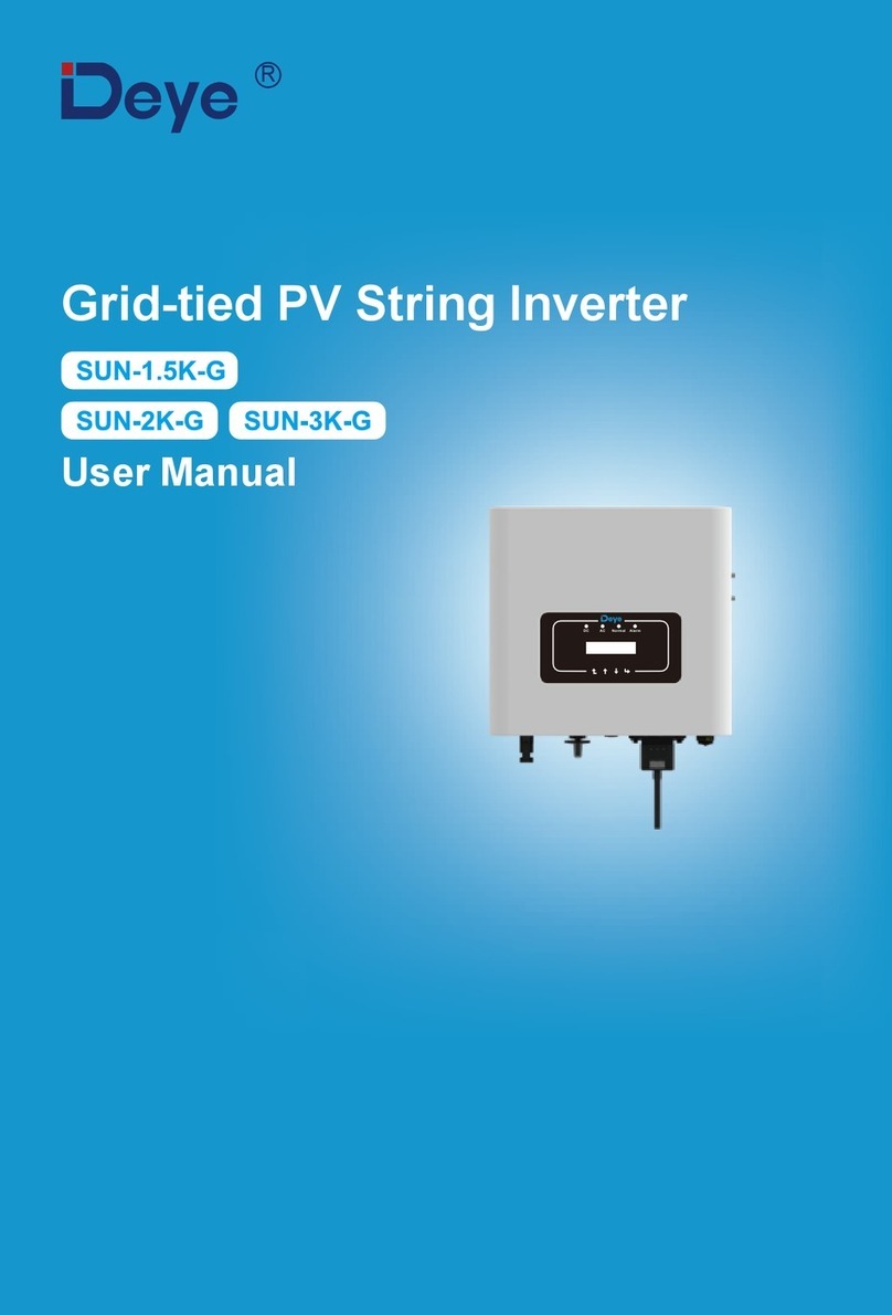
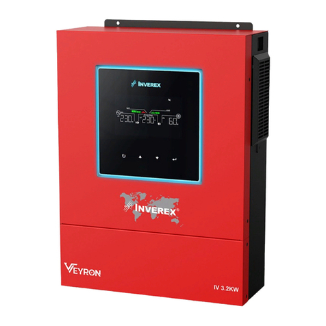
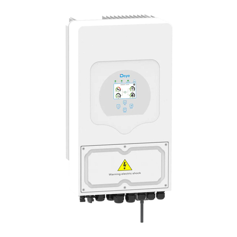
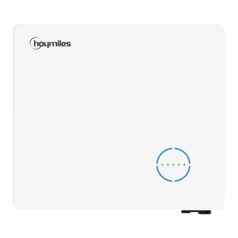
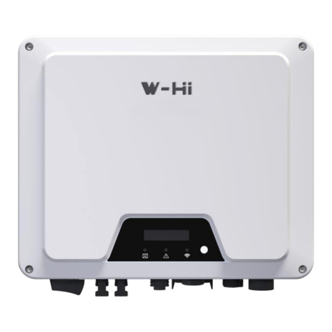
Deye SUN-5K-SG04LP3-AU User manual

Hybrid Inverter
User Manual
R
SUN-8K-SG04LP3-AU
SUN-5K-SG04LP3-AU
SUN-6K-SG04LP3-AU
SUN-10K-SG04LP3-AU
SUN-12K-SG04LP3-AU

ContentsContents
1. Safety Introductions
2. Product instructions
2.1 Product Overview
…………………………………………………
…………………………………………………
2.2 Product Size
01
01-04
2.3 Product Features
2.4 Basic System Architecture
2.5 Maintenance of the System
……………………………………………………………
3. Installation
3.1 Parts list
3.2 Mounting instructions
3.3 Battery connection
3.5 PV Connection
3.4 Grid connection and backup load connection
05-23
3.6 CT Connection
3.7 Earth Connection(mandatory)
3.8 WIFI Connection
3.9 Wiring System for Inverter
3.11 Typical application diagram of diesel generator
3.10 Wiring diagram
3.12 phase parallel connection diagram
……………………………………………………………………
6. Mode 38-39
5.6 Battery Setup Menu
5.7 System Work Mode Setup Menu
5.8 Grid Setup Menu
5.9 Generator Port Use Setup Menu
5.10 Advanced Function Setup Menu
5.11 Device Info Setup Menu
……………………………………………………………
……………………………………………………
4. OPERATION
4.1 Power ON/OFF
4.2 Operation and Display Panel
5. LCD Display Icons
5.1 Main Screen
5.2 Solar Power Curve
24
25-38
5.4 System Setup Menu
5.5 Basic Setup Menu
5.3 Curve Page-Solar & Load & Grid
………………………………………………
………………………………………………………………
7. Limitation of Liability
8. Datasheet
39-43
44-47
……………………………………………………………
9. Appendix I 48-49
……………………………………………………………
10. Appendix II 50
3.6.1 Meter Connection

- 01 -
1. Safety Introducons
· This chapter contains important safety and operang instrucons. Read and keep this manual
for future reference.
· Before using the inverter, please read the instrucons and warning signs of the baery and
corresponding secons in the instrucon manual.
· Do not disassemble the inverter. If you need maintenance or repair, take it to a professional
service center.
· Improper reassembly may result in electric shock or fire.
· To reduce risk of electric shock, disconnect all wires before aempng any maintenance or
cleaning. Turning off the unit will not reduce this risk.
· Cauon: Only qualified personnel can install this device with baery.
· Never charge a frozen baery.
· For opmum operaon of this inverter, please follow required specificaon to select appropriate
cable size. It is very important to correctly operate this inverter.
· Be very cauous when working with metal tools on or around baeries. Dropping a tool may
cause a spark or short circuit in baeries or other electrical parts, even cause an explosion.
· Please strictly follow installaon procedure when you want to disconnect AC or DC terminals.
Please refer to "Installaon" secon of this manual for the details.
· Grounding instrucons - this inverter should be connected to a permanent grounded wiring
system. Be sure to comply with local requirements and regulaon to install this inverter.
· Never cause AC output and DC input short circuited. Do not connect to the mains when DC
input short circuits.
2. Product Introducon
This is a mulfunconal inverter, combining funcons of inverter, solar charger and baery
charger to offer uninterrupble power support with portable size. Its comprehensive LCD display
offers user configurable and easy accessible buon operaon such as baery charging, AC/solar
charging, and acceptable input voltage based on different applicaons.
About This Manual
The manual mainly describes the product informaon, guidelines for installaon, operaon and
maintenance. The manual cannot include complete informaon about the photovoltaic (PV)
system.
How to Use This Manual
Read the manual and other related documents before performing any operaon on the inverter.
Documents must be stored carefully and be available at all mes.
Contents may be periodically updated or revised due to product development. The informaon
in this manual is subject to change without noce. The latest manual can be acquired via

2.1 Product Overview
- 02 -
1: Inverter indicators
2: LCD display
3: Funcon buons
5: DC switch
4: Power on/off buon
6: Parallel port
7: Meter-485 port
8: Baery input connectors
9: Funcon port
10: ModeBUS port
11: BMS port
12: PV input with two MPPT
13: Grid
15: Generator input
14: Load
16: WiFi Interface
17: DRM port
1
2
3
4
5
8
9
12
13
17
14
15
16
7
6
10
11

- 03 -
2.2 Product Size
Inverter Size
Mounng bracket

- 04 -
2.3 Product Features
- 230V/400V Three phase Pure sine wave inverter.
- Self-consumpon and feed-in to the grid.
- Auto restart while AC is recovering.
- Programmable supply priority for baery or grid.
- Programmable mulple operaon modes: On grid, off grid and UPS.
- Configurable baery charging current/voltage based on applicaons by LCD seng.
- Configurable AC/Solar/Generator Charger priority by LCD seng.
- Compable with mains voltage or generator power.
- Overload/over temperature/short circuit protecon.
- Smart baery charger design for opmized baery performance
- With limit funcon, prevent excess power overflow to the grid.
- Supporng WIFI monitoring and build-in 2 strings for 1 MPP tracker, 1 string for 1 MPP tracker.
- Smart seable three stages MPPT charging for opmized baery performance.
- Time of use funcon.
- Smart Load Funcon.
2.4 Basic System Architecture
2.5 Maintenance of the System
The following illustraon shows basic applicaon of this inverter.
It also includes following devices to have a Complete running system.
- Generator or Ulity
- PV modules
Consult with your system integrator for other possible system architectures depending on your
requirements.
This inverter can power all kinds of appliances in home or office environment, including motor
type appliances such as refrigerator and air condioner.
GridBackup Load
WiFI
GPRS
phoneCloud services
On-Grid Home Load
Generator
ATS
Grid-connected InverterSmart Load
Battery
Solar
CT
AC cable DC cable
The inverter is low maintenance, however, it is important that at least twice a year (for dusty
environments this may need to be carried out weekly) all the cooling fans, air ducts are cleaned
and dust free.Check if there are no fault codes and Lithium baery communicaon is correct.
Weekly cleaning statement:Suggest micromesh filters as an available opon.

- 05 -
3. Installaon
3.1 Parts List
Check the equipment before installaon. Please make sure nothing is damaged in the package.
You should have received the items in the following package:
Wall mounng bracket x1Hybrid inverter
x1
Parallel communicaon
cable x1
L-type Hexagon wrench
x1
Stainless steel an-collision
bolt M8×80
x4
User
manual
User manual x1
Baery temperature sensor
x1
Wi-Fi-Plug (oponal) x1
Sensor Clamp
x 3
Meter(oponal)
x 1
Three-Phase Smart Meter
SET ESC

- 06 -
3.2 Mounng instrucons
Installaon Precauon
This Hybrid inverter is designed for outdoor use(IP65), Please make sure the installaon site
meets below condions:
Please AVOID direct sunlight, rain exposure, snow laying up during installaon and
operaon. Before connecng all wires, please take off the metal cover by removing
screws as shown below:
· Not in direct sunlight
· Not in areas where highly flammable materials are stored.
· Not in potenal explosive areas.
· Not in the cool air directly.
· Not near the television Antenna or antenna cable.
· Not higher than altude of about 2000 meters above sea level.
· Not in environment of precipitaon or humidity(>95%)
Considering the following points before selecng where to install:
· Please select a vercal wall with load-bearing capacity for installaon, suitable for installaon
on concrete or other non-flammable surfaces,installaon is shown below.
· Install this inverter at eye level in order to allow the LCD display to be read at all mes.
· The ambient temperature should be between -25~60℃ to ensure opmal operaon.
· Be sure to keep other objects and surfaces as shown in the diagram to guarantee sufficient
heat dissipaon and have enough space for removing wires.

- 07 -
For proper air circulaon to dissipate heat, allow a clearance of approx. 50cm to the side and
approx. 50cm above and below the unit. And 100cm to the front.
Mounng the inverter
Remember that this inverter is heavy! Please be careful when liing out from the package.
Choose the recommend drill head(as shown in below pic) to drill 4 holes on the wall,
52-60mm deep.
1. Use a proper hammer to fit the expansion bolt into the holes.
2. Carry the inverter and holding it, make sure the hanger aim at the expansion bolt,fix the
inverter on the wall.
3. Fasten the screw head of the expansion bolt to finish the mounng.
≥500mm
≥500mm
Inverter hanging plate installaon

- 08 -
3.3 Baery connecon
Chart 3-2 Cable size
For safe operaon and compliance, a separate DC over-current protector or disconnect device is
required between the baery and the inverter. In some applicaons, switching devices may not
be required but over-current protectors are sll required. Refer to the typical amperage in the
table below for the required fuse or circuit breaker size.
Model
8Kw
6Kw
5Kw
Wire Size Cable(mm )
1AWG
1AWG
2AWG
2
40
40
35
Torque value(max)
24.5Nm
24.5Nm
24.5Nm
10Kw 1/0AWG 60 24.5Nm
12Kw 1/0AWG 60 24.5Nm

- 09 -
Please follow below steps to implement baery connecon:
1. Please choose a suitable baery cable with correct connector which can well fit into the
baery terminals.
2. Use a suitable screwdriver to unscrew the bolts and fit the baery connectors in, then
fasten the bolt by the screwdriver, make sure the bolts are ghtened with torque of
24.5 N.M in clockwise direcon.
3. Make sure polarity at both the baery and inverter is correctly connected.
Connecng the baery with a suitable cable is important for safe and efficient
operaon of the system. To reduce the risk of injury, refer to Chart 3-2 for
recommended cables.
All wiring must be performed by a professional person.
3. In case of children touch or insects go into the inverter, Please make sure the inverter
connector is fasten to waterproof posion by twist it clockwise.
Before making the final DC connecon or closing DC breaker/disconnect, be sure
posive(+) must be connect to posive(+) and negave(-) must be connected to
negave(-). Reverse polarity connecon on baery will damage the inverter.
Installaon must be performed with care.

12
Temp. CT
- 11 -
3.3.3 Temperature sensor connecon for lead-acid baery
Inverter

- 10 -
Batt Temp
Sensor
1 2 3 4 5 6 7 8 1 2 3 4 5 6 7 8
CN1:
TEMP (1,2): baery temperature sensor for lead
acid baery.
CT-L1 (3,4): current transformer (CT1) for“zero
export to CT”mode clamps on L1 when
in three phase system.
CT-L2 (5,6): current transformer (CT2) for“zero
export to CT”mode clamps on L2 when
in three phase system.
CT-L3 (7,8): current transformer (CT3) for“zero export to CT”mode clamps on L3 when in
three phase system.
CN2:
G-start (1,2): dry contact signal for startup the
diesel generator.
When the "GEN signal" is acve, the open contact
(GS) will switch on (no voltage output).
G-valve (3,4): reserved.
Grid_Ry (5,6):
RSD (7,8): When baery is connected and the
inverter is in "ON" status, it will provide 12Vdc.
Parallel A: Parallel communicaon
port 1 (CAN interface).
Parallel B: Parallel communicaon
port 2 (CAN interface).
Meter_485: for energy meter
communicaon.
ModeBUS: Reserved.
BMS: BMS port for baery
communicaon(CAN/RS485).
DRM port:Logic interface for
AS/NZS 4777.2:2020
CT -L1
CT -L2
CT -L3
Gen start-up
N/O Relay
Parallel_A
CN1: TEMP: 1,2
CT_1: 3,4
CT_2: 5,6
CT_3: 7,8
Parallel_B Meter-485
ModeBUS BMS
GS (diesel generator startup signal)
relay
coil
open
contact
G S
3.3.2 Funcon port definion
CN2: G_start: 1,2
G_valve: 3,4
Grid_Ry: 5,6
RSD: 7+, 8-
CN1 CN2
Inverter
DRM port

T(L3)
PE
S(L2)
R(L1)
N
- 12 -
3.4 Grid connecon and backup load connecon
1. Before making Grid, load and Gen port connecon, be sure to turn off AC baeaker or
disconnector first.
2. Remove insulaon sleeve 10mm length, unscrew the bolts, insert the wires according to
polaries indicated on the terminal block and ghten the terminal screws. Make sure the
connecon is complete.
Please follow below steps to implement Grid, load and Gen port connecon:
Chart 3-3 Recommended Size for AC wires
· Before connecng to grid, please install a separate AC breaker between inverter and grid. Also,
it is recommended that installs an AC breaker between backup load and inverter.This will ensure
the inverter can be securely disconnected during maintenance and fully protected from over
current.The recommended of AC breaker for the load port is 20A for 8kw, 32A for 10kw and
32A for 12KW. The recommended of AC breaker for the grid port is 63A for 8kw, 63A for 10kw
and 63A for 12KW.
All wiring must be performed by a qualified personnel.It is very important for
system safety and efficient operaon to use appropriate cable for AC input
connecon. To reduce risk of injury, please use the proper recommended cable
as below.
Model
5/6/8/10/12KW
Wire Size
10AWG
Cable(mm )
2
4
Torque value(max)
1.2Nm
Model
5/6/8/10/12KW
Wire Size
10AWG
Cable(mm )
2
6
Torque value(max)
1.2Nm
T(L3)
PE
S(L2)
R(L1)
N
GRID
T(L3)
PE
S(L2)
R(L1)
NGEN PORT
LOAD
Grid connecon
backup load connecon
· There are three terminal blocks with "Grid" "Load"and "GEN" markings. Please do not misconnect
input and output connectors.
GRID LOAD GEN PORT

- 13 -
3.5 PV Connecon
3. Then, insert AC output wires according to polaries indicated on the terminal block and ghten
terminal. Be sure to connect corresponding N wires and PE wires to related terminals as well.
4. Make sure the wires are securely connected.
5. Appliances such as air condioner are required at least 2-3 minutes to restart because it is
required to have enough me to balance refrigerant gas inside of circuit. If a power shortage
occurs and recovers in short me, it will cause damage to your connected appliances. To
prevent this kind of damage, please check manufacturer of air condioner if it is equipped with
me-delay funcon before installaon. Otherwise, this inverter will trigger overload fault and
cut off output to protect your appliance but somemes it sll causes internal damage to the air
condioner
Before connecng to PV modules, please install a separately DC circuit breaker between
inverter and PV modules. It is very important for system safety and efficient operaon to
use appropriate cable for PV module connecon. To reduce risk of injury, please use the
proper recommended cable size as below.
Chart 3-4 Cable size
Be sure that AC power source is disconnected before aempng to wire it to the
unit.
To avoid any malfuncon, do not connect any PV modules with possible current
leakage to the inverter. For example, grounded PV modules will cause current
leakage to the inverter. When using PV modules, please be sure NO grounding.
It is requested to use PV juncon box with surge protecon. Otherwise, it will
cause damage on inverter when lightning occurs on PV modules.
Model
5/6/8/10/12KW
Wire Size
12AWG
Cable(mm )
2
4

- 14 -
3.5.1 PV Module Selecon:
3.5.2 PV Module Wire Connecon:
When selecng proper PV modules, please be sure to consider below parameters:
1) Open circuit Voltage (Voc) of PV modules not exceeds max. PV array open circuit voltage of
inverter.
2) Open circuit Voltage (Voc) of PV modules should be higher than min. start voltage.
Chart 3-5
PV Input Voltage
Inverter Model SUN-10K-
SG04LP3-AU
SUN-8K-
SG04LP3-AU
SUN-6K-
SG04LP3-AU
SUN-5K-
SG04LP3-AU
SUN-12K-
SG04LP3-AU
550V (160V~800V)
200V-650VPV Array MPPT Voltage Range
No. of MPP Trackers
No. of Strings per MPP Tracker
2
2+1
1+11+1 1+1 2+1
1. Switch the Grid Supply Main Switch(AC)OFF.
2. Switch the DC lsolator OFF.
3. Assemble PV input connector to the inverter.
Safety Hint:
Please don’t connect PV array posive or negave pole to the ground, it could
cause serious damages to the inverter.
Safety Hint:
Before connecng inverter, please make sure the PV array open circuit voltage is
within the 1000V of the inverter.
GFDI fault:
Before the inverter starts to connect to the grid, the inverter will first
detect the impedance of PV + to ground, and the impedance of PV-
to ground. If any of these impedance values is less than 33 kΩ, the
inverter will not connect to the grid and will report an error
F04 on its LCD.At the same me, the buzzer will sound.
Safety Hint:
Before connecon, please make sure the polarity of the output voltage of PV
array matches the “DC+” and “DC-” symbols.
Pic 5.1 DC+ male connector (MC4) Pic 5.2 DC- female connector (MC4)

- 15 -
Safety Hint:
Please use approved DC cable for PV system.
Cable type Range Recommended value
Cross secon(mm )
Industry generic PV cable
(model: PV1-F)
4.0~6.0
(12~10AWG) 4.0(12AWG)
The steps to assemble the DC connectors are listed as follows:
a) Strip off the DC wire about 7mm, disassemble the connector cap nut (see picture 5.3).
b) Crimping metal terminals with crimping pliers as shown in picture 5.4.
c) Insert the contact pin to the top part of the connector and screw up the cap nut to the top
part of the connector. (as shown in picture 5.5).
Pic 3.3 Disassemble the connector cap nut
7mm
7mm
Pic 3.4 Crimp the contact pin to the wire
Chart 3-6

- 16 -
Pic 3.5 connector with cap nut screwed on
d) Finally insert the DC connector into the posive and negave input of the inverter, shown as
picture 5.6
Pic 3.6 DC input connecon
Warning:
Sunlight shines on the panel will generate voltage, high voltage in series may
cause danger to life. Therefore, before connecng the DC input line, the solar
panel needs to be blocked by the opaque material and the DC switch should
be 'OFF', otherwise, the high voltage of the inverter may lead to life-
threatening condions.

- 17 -
3.6 CT Connecon
White wire 543 6 7 8
Black wire
Grid
N
R
S
T
CT1
CT2
CT3
GRID
N
RST
PE
CT
Arrow pointing
to inverter
*Note:when the reading of the load power on the LCD is not correct, please
reverse the CT arrow.
Inverter

GRID
N
RST
PE
- 18 -
3.6.1 Meter Connecon
R
S
T
N
PE
Parallel_A Parallel_B Meter-485 port
RS485A
RS485B
Three-Phase Smart Meter
SET ESC
1 74 10
2524
3
96 10
CHINT meter
Three-Phase Smart Meter
SET ESC
1 74 10
2524
3 96 10
RS 485
CHNT DTSU666
(3,6,9,10)
(1,4,7,10)
R
S
T
Grid
R
R
S
S
T
T
N
N
Parallel_A Parallel_B Meter-485 port
RS485A
RS485B
Grid
Eastron meterEastron SDM630-Modbus V2
RS 485
RS 485 B RS 485 A
B A G
(5,6,7,8)
(1,2,3,4)
1234
R
S
T
5678
GND
Eastron
5 6 7 8
R
S
T
Eastron
5 6 7 8
GRID
N
RST
PE
Inverter
Inverter
PE
GND
This manual suits for next models
4
Table of contents
Other Deye Inverter manuals

Deye
Deye SUN-70K-G03 User manual

Deye
Deye SUN-6K-SG04LP3-AU User manual

Deye
Deye SUN-40K-G-LV User manual

Deye
Deye SUN-36K-G04 User manual

Deye
Deye SUN-12K-G03 User manual

Deye
Deye SUN-17K-G05 User manual

Deye
Deye SUN600G Instruction Manual
Deye
Deye SUN-15K-G05-AU User manual

Deye
Deye SUN-12K-G02-LV User manual

Deye
Deye SUN-7K-G User manual

Deye
Deye SUN-60K-G User manual

Deye
Deye SUN-25K-G04 User manual

Deye
Deye SUN-18K-G04 User manual

Deye
Deye SUN-35K-G-LV User manual

Deye
Deye SUN-15K-G03 User manual

Deye
Deye SUN-40K-G03 User manual

Deye
Deye SUN-8K-SG04LP3 User manual

Deye
Deye SUN-3.6K-G User manual
Deye
Deye SUN-30K-G03 User manual

Deye
Deye SUN-8K-SG04LP3 User manual