DeZURIK 20-144” BAW AWWA
Butterfly Valves with Epoxy-Retained Seat
April 2017 Page 4 D10373
Description
The 20-120” BAW AWWA Butterfly Valve is a resilient seated valve, which conforms to all of the
AWWA C504 requirements. DeZURIK offers the BAW AWWA Butterfly Valve in a mechanical joint end
style per ANSI/AWWA C111/A 21.11-85 in the 20–48" size range. The flanged end style is available in
all sizes.
The 20-144” BAW AWWA Butterfly Valve is available in AWWA C504 Classes 25A, 75 B, 150B and
250 B. It is capable of bi-directional shutoff to the full rated pressure. See the data plate attached to the
valve for pressure and temperature limitation information.
The actuator has been sized for the valve shutoff pressure specified by the customer. If the valve is to
be used at a shutoff pressure higher than that specified, consult the factory for sizing information.
Handling
Lifting the valve improperly may damage it. Do not fasten lifting devices to the actuator, disc or through
the seat opening in the body. Lift the valve with slings, chains or cables fastened around the valve
body, or fastened to bolts or rods through bolt holes in the flanges.
Maintenance
This valve is assembled using standard SAE fasteners. To service this valve, you should have a full set
of combination wrenches, flat tipped screwdrivers, Allen wrenches, a torque wrench, sockets, chisels, a
hooked tool for removing the packing and a dead blow hammer.
Lubrication
The valve is lubricated at the factory, and does not require routine lubrication. When installing valve or if
maintenance is required, refer to the appropriate sections for lubrication requirements and use an
NSF 61 approved lubricant (such as Dow Corning 111 or Phoenix 505).
Refer to the actuator instructions for actuator lubrication requirements.
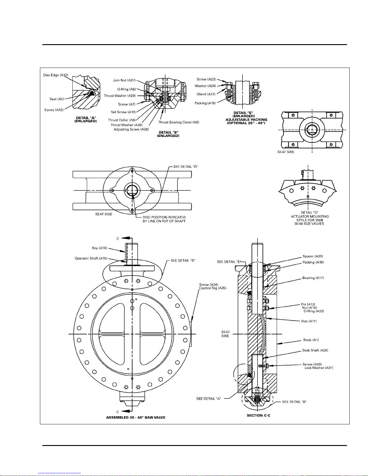
Closed Position
The valve is in the closed position when the disc is parallel to the flange face. The actuator stops have
been adjusted at the factory to stop valve rotation in the proper closed position. See the actuator
Instruction for details on adjusting the open and closed position stops.
An indicator mark corresponding with the seat side of the disc is stamped on top of the valve shaft to
show the position of the disc when the disc is not visible. The location of the indicator mark is shown on
the valve assembly and installation drawings.
Fusion/Powder Coated Valves
Valves with fusion/powder coated exterior paint require flat washers to be installed
under the flange nuts when installing the valve to the pipeline flange to prevent the
paint from cracking or chipping.