DFI AL171 User manual

1
AL171/AL173
Mini-ITX Industrial Motherboard
User’s Manual
A44200819

2
Copyright
This publication contains information that is protected by copyright. No part of it may be re-
produced in any form or by any means or used to make any transformation/adaptation without
the prior written permission from the copyright holders.
This publication is provided for informational purposes only. The manufacturer makes no
representations or warranties with respect to the contents or use of this manual and specifi-
cally disclaims any express or implied warranties of merchantability or fitness for any particular
purpose. The user will assume the entire risk of the use or the results of the use of this docu-
ment. Further, the manufacturer reserves the right to revise this publication and make changes
to its contents at any time, without obligation to notify any person or entity of such revisions
or changes.
Changes after the publication’s first release will be based on the product’s revision. The website
will always provide the most updated information.
© 2018. All Rights Reserved.
Trademarks
Product names or trademarks appearing in this manual are for identification purpose only and
are the properties of the respective owners.
FCC and DOC Statement on Class B
This equipment has been tested and found to comply with the limits for a Class B digital
device, pursuant to Part 15 of the FCC rules. These limits are designed to provide reason-
able protection against harmful interference when the equipment is operated in a residential
installation. This equipment generates, uses and can radiate radio frequency energy and, if not
installed and used in accordance with the instruction manual, may cause harmful interference
to radio communications. However, there is no guarantee that interference will not occur in a
particular installation. If this equipment does cause harmful interference to radio or television
reception, which can be determined by turning the equipment off and on, the user is encour-
aged to try to correct the interference by one or more of the following measures:
• Reorient or relocate the receiving antenna.
• Increase the separation between the equipment and the receiver.
• Connect the equipment into an outlet on a circuit different from that to which the receiver
is connected.
• Consult the dealer or an experienced radio TV technician for help.
Notice:
1. The changes or modifications not expressly approved by the party responsible for compli-
ance could void the user’s authority to operate the equipment.
2. Shielded interface cables must be used in order to comply with the emission limits.

3
Copyright.............................................................................................................2
Trademarks........................................................................................................2
FCC and DOC Statement on Class B.....................................................2
Warranty..............................................................................................................4
Static Electricity Precautions......................................................................4
Safety Measures..............................................................................................4
About the Package.........................................................................................5
Optional Items..................................................................................................5
Before Using the System Board...............................................................5
Chapter 1 - Introduction.............................................................................6
Specifications ................................................................................................6
Features..........................................................................................................7
Chapter 2 - Hardware Installation................................................8
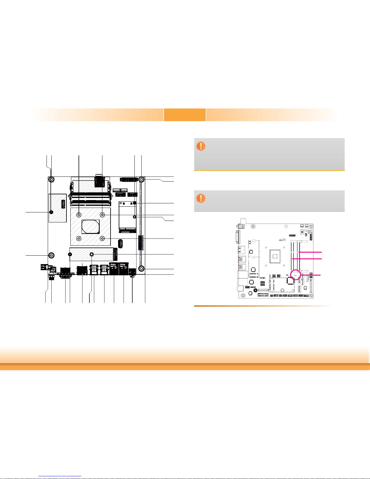
Board Layout.................................................................................................8
Block Diagram...............................................................................................8
Mechanical Diagram....................................................................................9
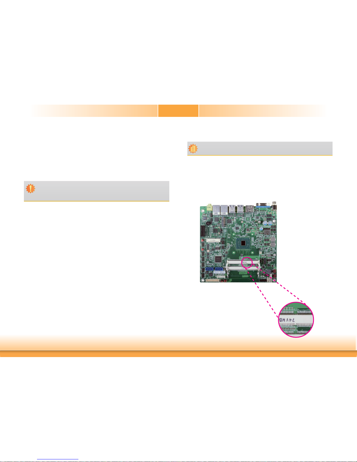
System Memory............................................................................................9
Installing the DIMM Module ........................................................................10
Installing the Heat Sink...........................................................................11
Jumper Settings .........................................................................................12
Clear CMOS Data........................................................................................12
SATA 1/M.2 B Key SATA Signal Select..........................................................13
M.2 Signal Select........................................................................................13
COM1/COM2 RS232/Power Select................................................................14
LCD/Inverter Power Select..........................................................................15
Backlight Power Select................................................................................ 15
Panel Power Select.....................................................................................16
PCIE1/M.2 B Key PCIE Signal Select............................................................16
Rear Panel I/O Ports.................................................................................17
12V DC-in (AL171)/15~36V (AL173)............................................................17
Graphics Interface ...................................................................................... 18
RJ45 LAN Ports...........................................................................................18
USB Ports...................................................................................................19
Audio.........................................................................................................19
I/O Connectors........................................................................................... 20
SATA (Serial ATA) Connectors...................................................................... 20
SATA (Serial ATA) Power Connectors............................................................ 20
S/PDIF Connector.......................................................................................21
Digital I/O and Power Connectors................................................................21
Cooling Fan Connectors...............................................................................22
Front Panel Connector ................................................................................22
COM (Serial) Ports......................................................................................23
LVDS LCD Panel Connector .........................................................................24
LCD/Inverter Power Connector....................................................................24
SMBus Connector .......................................................................................25
Standby Power LED....................................................................................25
Chassis Intrusion Connector........................................................................26
Expansion Slots..........................................................................................26
LPC Connector............................................................................................27
Connecting the EXT-RS232/RS485 Card to the Motherboard .........................27
eDP Connector (optional)............................................................................28
Battery....................................................................................................... 29
Chapter 3 - BIOS Setup............................................................... 30
Overview .....................................................................................................30
Insyde BIOS Setup Utility........................................................................ 31
Main ..........................................................................................................31
Advanced...................................................................................................31
Security......................................................................................................39
Boot...........................................................................................................40
Exit............................................................................................................41
Updating the BIOS....................................................................................42
Notice: BIOS SPI ROM.............................................................................42
Chapter 4 - Supported Software...........................................................43
Appendix A - Troubleshooting Checklist............................................49
Table of Contents

4
Warranty
1. Warranty does not cover damages or failures that arised from misuse of the product,
inability to use the product, unauthorized replacement or alteration of components and
product specifications.
2. The warranty is void if the product has been subjected to physical abuse, improper instal-
lation, modification, accidents or unauthorized repair of the product.
3. Unless otherwise instructed in this user’s manual, the user may not, under any circum-
stances, attempt to perform service, adjustments or repairs on the product, whether in or
out of warranty. It must be returned to the purchase point, factory or authorized service
agency for all such work.
4. We will not be liable for any indirect, special, incidental or consequencial damages to the
product that has been modified or altered.
Static Electricity Precautions
It is quite easy to inadvertently damage your PC, system board, components or devices even
before installing them in your system unit. Static electrical discharge can damage computer
components without causing any signs of physical damage. You must take extra care in han-
dling them to ensure against electrostatic build-up.
1. To prevent electrostatic build-up, leave the system board in its anti-static bag until you are
ready to install it.
2. Wear an antistatic wrist strap.
3. Do all preparation work on a static-free surface.
4. Hold the device only by its edges. Be careful not to touch any of the components, contacts
or connections.
5. Avoid touching the pins or contacts on all modules and connectors. Hold modules or con-
nectors by their ends.
Safety Measures
To avoid damage to the system:
• Use the correct AC input voltage range.
To reduce the risk of electric shock:
• Unplug the power cord before removing the system chassis cover for installation or servic-
ing. After installation or servicing, cover the system chassis before plugging the power
cord.
Important:
Electrostatic discharge (ESD) can damage your processor, disk drive and other com-
ponents. Perform the upgrade instruction procedures described at an ESD worksta-
tion only. If such a station is not available, you can provide some ESD protection by
wearing an antistatic wrist strap and attaching it to a metal part of the system chas-
sis. If a wrist strap is unavailable, establish and maintain contact with the system
chassis throughout any procedures requiring ESD protection.

5
About the Package
The package contains the following items. If any of these items are missing or damaged,
please contact your dealer or sales representative for assistance.
• 1 AL171/AL173 motherboard
• 1 COM port cable (Length: 250mm, 1 x COM port)
• 1 Serial ATA data with power cable (Length: 300mm)
The board and accessories in the package may not come similar to the information listed
above. This may differ in accordance to the sales region or models in which it was sold. For
more information about the standard package in your region, please contact your dealer or
sales representative.
Optional Items
• USB port cable (Length: 200mm)
• COM port cable (Length: 250mm, 1 x COM port)
• Serial ATA data with power cable (Length: 300mm)
• LPC EXT-RS232 module (4 x RS232 ports)
• LPC EXT-RS485 module (4 x RS485 ports)
• I/O shield
• Heat sink for 0 to 60°C (Height: 19mm)
• Heat sink for -40 to 85°C (Height: 32mm)
• Thermal solution (For 35W, Height: 37.3mm)
• Thermal solution (For 65W, Height: 72.8mm)
• Thermal solution (For 95W)
The board and accessories in the package may not come similar to the information listed-
above. This may differ in accordance to the sales region or models in which it was sold. For
more information about the standard package in your region, please contact your dealer or
sales representative.
Before Using the System Board
Before using the system board, prepare basic system components.
If you are installing the system board in a new system, you will need at least the following
internal components.
• Memory module
• Storage devices such as hard disk drive, etc.
You will also need external system peripherals you intend to use which will normally include at
least a keyboard, a mouse and a video display monitor.
This manual suits for next models
1
Table of contents
Other DFI Motherboard manuals