DFI M8MP553 User manual

M8MP553
3.5" SBC Motherboard
User’s Manual
© February 10, 2023 DFI Inc.

2User's Manual | M8MP553
Copyright
This publication contains information that is protected by copyright. No part of it may be
reproduced in any form or by any means or used to make any transformation/adaptation
without the prior written permission from the copyright holders.
This publication is provided for informational purposes only. The manufacturer makes
no representations or warranties with respect to the contents or use of this manual and
specifically disclaims any express or implied warranties of merchantability or fitness for any
particular purpose. The user will assume the entire risk of the use or the results of the use of
this document. Further, the manufacturer reserves the right to revise this publication and make
changes to its contents at any time, without obligation to notify any person or entity of such
revisions or changes.
Changes after the publication’s first release will be based on the product’s revision. The website
will always provide the most updated information.
© 2021. All Rights Reserved.
Trademarks
Product names or trademarks appearing in this manual are for identification purpose only and
are the properties of the respective owners.
FCC and DOC Statement on Class B
This equipment has been tested and found to comply with the limits for a Class B digital
device, pursuant to Part 15 of the FCC rules. These limits are designed to provide reasonable
protection against harmful interference when the equipment is operated in a residential
installation. This equipment generates, uses and can radiate radio frequency energy and, if not
installed and used in accordance with the instruction manual, may cause harmful interference
to radio communications. However, there is no guarantee that interference will not occur
in a particular installation. If this equipment does cause harmful interference to radio or
television reception, which can be determined by turning the equipment off and on, the user is
encouraged to try to correct the interference by one or more of the following measures:
• Reorient or relocate the receiving antenna.
• Increase the separation between the equipment and the receiver.
• Connect the equipment into an outlet on a circuit different from that to which the
receiver is connected.
• Consult the dealer or an experienced radio TV technician for help.
Notice:
1. The changes or modifications not expressly approved by the party responsible for
compliance could void the user’s authority to operate the equipment.
2. Shielded interface cables must be used in order to comply with the emission limits.

3User's Manual | M8MP553
Table of Contents
Chapter 1 - Introduction................................................................................................................6
Specifications ......................................................................................................................... 6
Block Diagram ........................................................................................................................8
Chapter 2 - Hardware Installation................................................................................................9
Board Layout...........................................................................................................................9
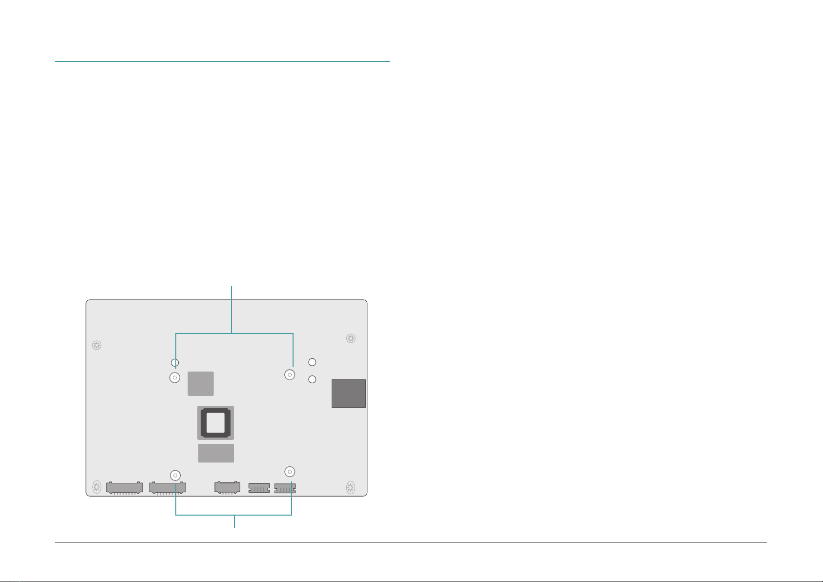
Installing the Heat Sink.................................................................................................10
Jumper Settings ...................................................................................................................11
Boot-CNFG (JP1) ...........................................................................................................11
LED Backlight (BLJP1) ..................................................................................................11
External I/O Ports.................................................................................................................12
9~36V DC-in (CN14) ....................................................................................................12
USB 2.0/3.1 & Micro USB (UBCN2 / UBCN1 & UBCN3).............................................13
LAN1 / LAN2 (ETCN1 / ETCN2)...................................................................................13
COM 3 (TSCN1) .............................................................................................................14
HDMI (DPCN1)...............................................................................................................14
uSD Slot (SDCN1)..........................................................................................................15
Internal I/O Connectors .......................................................................................................16
USB2_3/4 (UBJ1)...........................................................................................................16
Debug Port (COM2, J10)...............................................................................................16
Audio (AUJP1) ...............................................................................................................17
I2C (TPJP1) ....................................................................................................................17
DIO (IOJP1) ....................................................................................................................18
Front Panel (FPJP1) ......................................................................................................18
COM1 / COM4 (TSJP1).................................................................................................19
I2C / Touch (TPJ1) ........................................................................................................19
LCD Backlight (BLJ1) ....................................................................................................20
CAN1 & CAN2 (CBCN1 & CBCN2) ...............................................................................20
FAN (SFJ1)......................................................................................................................21
SPI (SPJP1)....................................................................................................................21
LCD LVDS (DPJ1)...........................................................................................................22
JTAG (J1) .......................................................................................................................23
Battery (BTJ1) ................................................................................................................23
Expansion Slots....................................................................................................................24
Installing the M.2 Module .............................................................................................24
Chapter 3 - Software User Guide...............................................................................................25
Flash Yocto Images to eMMC using UUU tool - V1.1 .......................................................25
Flash Yocto Images to SD using UUU tool - V1.1..............................................................28
Flash Android Images to eMMC/SD using UUU tool - V1.1 .............................................31
Software Feature..................................................................................................................34
General Support List......................................................................................................34
Linux AP/API Support List ............................................................................................34
Yocto Support List.........................................................................................................34
Android Support List .....................................................................................................35

4User's Manual | M8MP553
About this Manual
This manual can be downloaded from the website.
The manual is subject to change and update without notice, and may be based on editions
that do not resemble your actual products. Please visit our website or contact our sales
representatives for the latest editions.
Warranty
1. Warranty does not cover damages or failures that arise from misuse of the product,
inability to use the product, unauthorized replacement or alteration of components and
product specifications.
2. The warranty is void if the product has been subjected to physical abuse, improper
installation, modification, accidents or unauthorized repair of the product.
3. Unless otherwise instructed in this user’s manual, the user may not, under any
circumstances, attempt to perform service, adjustments or repairs on the product,
whether in or out of warranty. It must be returned to the purchase point, factory or
authorized service agency for all such work.
4. We will not be liable for any indirect, special, incidental or consequential damages to
the product that has been modified or altered.
Static Electricity Precautions
It is quite easy to inadvertently damage your PC, system board, components or devices even
before installing them in your system unit. Static electrical discharge can damage computer
components without causing any signs of physical damage. You must take extra care in
handling them to ensure against electrostatic build-up.
1. To prevent electrostatic build-up, leave the system board in its anti-static bag until you
are ready to install it.
2. Wear an antistatic wrist strap.
3. Do all preparation work on a static-free surface.
4. Hold the device only by its edges. Be careful not to touch any of the components,
contacts or connections.
5. Avoid touching the pins or contacts on all modules and connectors. Hold modules or
connectors by their ends.
Important:
Electrostatic discharge (ESD) can damage your processor, disk drive and other
components. Perform the upgrade instruction procedures described at an ESD
workstation only. If such a station is not available, you can provide some ESD
protection by wearing an antistatic wrist strap and attaching it to a metal part
of the system chassis. If a wrist strap is unavailable, establish and maintain
contact with the system chassis throughout any procedures requiring ESD
protection.
Safety Measures
• To avoid damage to the system, use the correct AC input voltage range.
• To reduce the risk of electric shock, unplug the power cord before removing the
system chassis cover for installation or servicing. After installation or servicing, cover
the system chassis before plugging the power cord.

5User's Manual | M8MP553
About the Package
The package contains the following items. If any of these items are missing or damaged,
please contact your dealer or sales representative for assistance.
• 1 M8MP553 board
• 1 Terminal block for RS485 (COM3) 342-361021-000G
• 1 Heatsink (Height: 21mm) A71-008168-000G
Note: The items are subject to change in the developing stage.
The board and accessories in the package may not come similar to the information listed
above. This may differ in accordance with the sales region or models in which it was sold. For
more information about the standard package in your region, please contact your dealer or
sales representative.
Before Using the System Board
When installing the system board in a new system, you will need at least the following internal
components.
• Power adapter
External system peripherals may also be required for navigation and display, including at least a
keyboard, a mouse and a video display monitor.
Other manuals for M8MP553
1
Table of contents
Other DFI Motherboard manuals