manuals.online logo
Brands
  1. Home
  2. •
  3. Brands
  4. •
  5. DG Flugzeugbau
  6. •
  7. Aircraft
  8. •
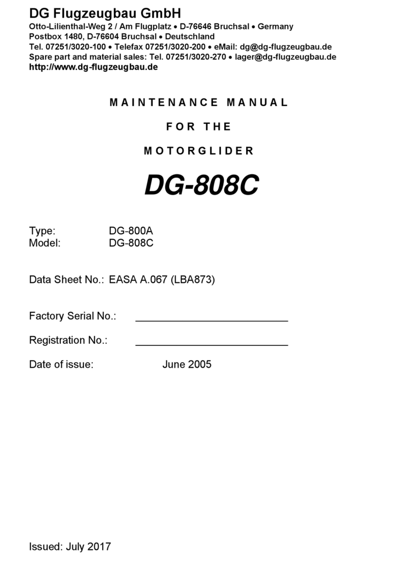
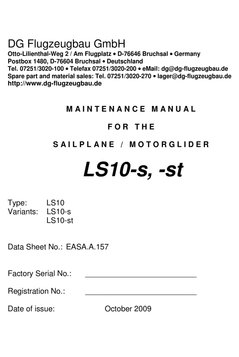
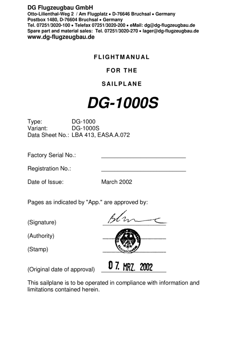
  9. DG Flugzeugbau DG-1000T User manual

DG Flugzeugbau DG-1000T User manual

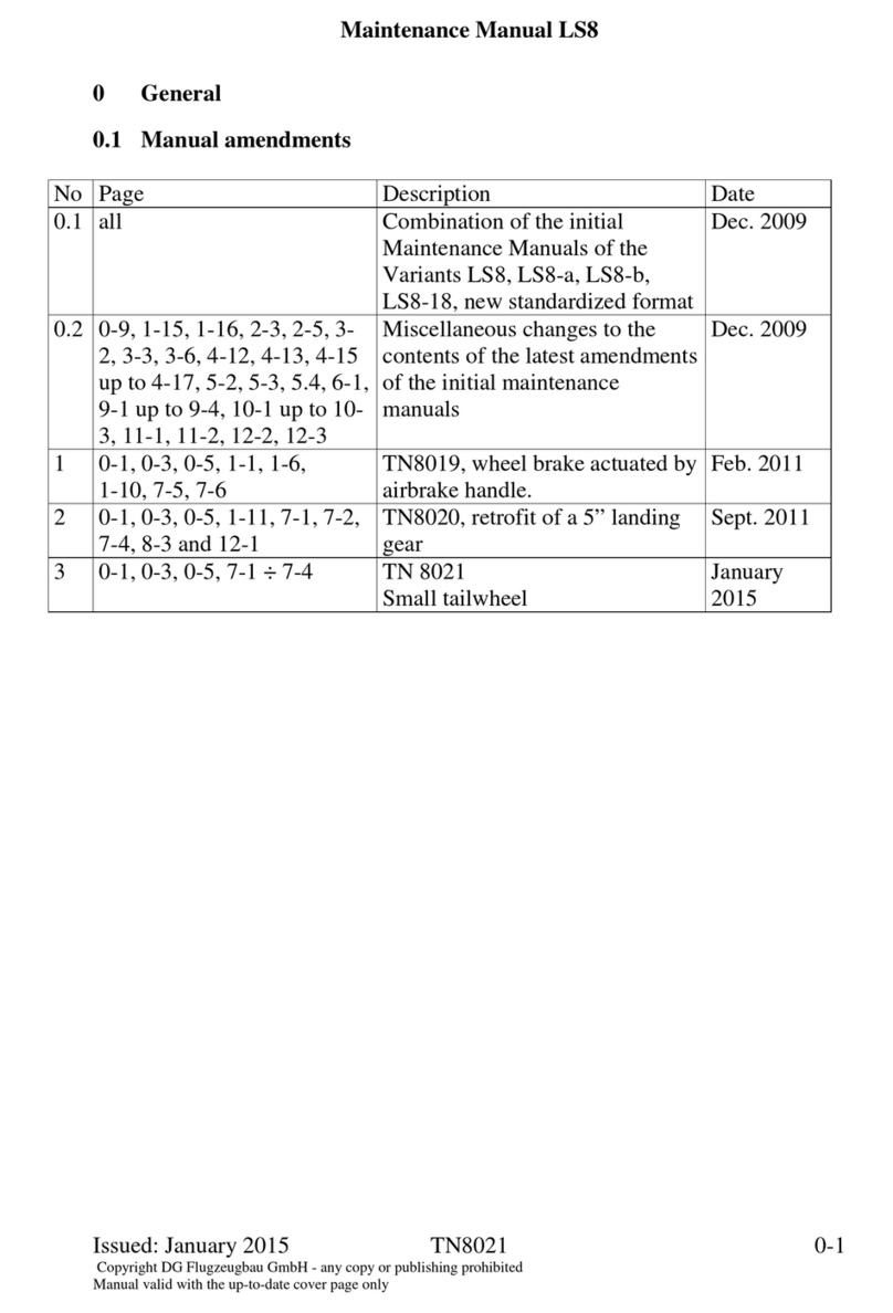
Maintenance Manual DG-1000T
Issued: March 2008 ÄM1000-02 0.1
0General
0.1 Manual amendments
No. Page Description Date
1 0.3, 0.6, 0.10, 1.22,
1.23, diagram 15a
TN1000/09 October
2006
2 0.5, 0.6, 8.2,
diagram 15a
ÄM 1000-1-07 December
2006
3 0.0, 0.3-0.6, 0.12, 1.1,
3.3, 4.2, 4.16, 4.17,
4.21, 4.28, 8.1, 8.4
diagrams 5, 6, 8 - 10,
12, 15, 15a,
5EP50, 5V18, 10FW2,
encl. 2 page 1
TN1000/10
Manual revision
January
2007
4 0.1, 0.6, diagram 14 TN1000/11
Manual revision
October
2007
5 0.3, 0.4, 0.6, 0.10, 1.9,
1.10, 4.7 – 4.9
diagrams 17, 18
landing gear positive locking
device TN1000/13
February
2008
6 0.3, 0.4, 0.6, 0.10,
1.19, 2.1, diagram 19,
enclosure 3
TN1000/15
Throttle handle in rear Cockpit
Option
March 2008
7 0.3, 0.6, 0.10, 1.14
diagram 6a
ÄM 1000-02
Fin ballast tank valve and handle
March 2008
Maintenance Manual DG-1000T
Issued: March 2008 ÄM1000/02 0.3
0.2 List of effective pages
Section page issued replaced/ replaced/ replaced/
0 0.0 June 2005 January 2007
0.1 see manual amendments
0.2 "
0.3 "
0.4 "
0.5 "
0.6 "
0.7 June 2005 January 2007
0.8 "
0.9 "
0.10 " Febr. 2008 March 2008
0.11 "
0.12 " January 2007
1 1.1 June 2005 January 2007
1.2 "
1.3 "
1.4 "
1.5 "
1.6 "
1.7 "
1.8 "
1.9 " Febr. 2008
1.10 " Febr. 2008
1.11 "
1.12 "
1.13 "
1.14 " March 2008
1.15 "
1.16 "
1.17 "
1.18
"
1.19
"
March 2008
1.20
"
1.21
"
1.22
"
October 2006
1.23
"
October 2006
1.24
"
1.25
"
Maintenance Manual DG-1000T
Issued: March 2008 TN 1000/15
0.4
0.2 List of effective pages (continued)
Section page issued replaced/ replaced/ replaced/
1.26 "
1.27
"
1.28
"
1.26
"
1.30
"
1.31
"
1.32
"
1.33
"
2 2.1 June 2005 March 2008
2.2 "
2.3 "
2.4 "
2.5 "
2.6 "
3 3.1 June 2005
3.2 "
3.3 "
3.4 "
3.5
3.6
3.7
3.8
3.9
4 4.1 June 2005
4.2 " January 2007
4.3 "
4.4 "
4.5 "
4.6 "
4.7 " Febr. 2008
4.8 "
4.9 " Febr. 2008
4.10 "
4.11 "
4.12 "
4.13 "
Maintenance Manual DG-1000T
Issued: March 2008 ÄM1000/02
0.6
0.2 List of effective pages (continued)
diagram issued replaced/ replaced/ replaced/
1 May 2004
2 Nov. 2001
3 June 2005
4 Nov. 2001
5 Nov. 2001 January 2007
6 Nov. 2001 January 2007 March 2008 Not valid for
10-101, and from 10-128 on
6a March 2008
7 Nov. 2004
8 Nov. 2001 January 2007
9 June 2005 January 2007
10 May. 2005 January 2007
11 June 2005
12 Sept. 2003 January 2007
13 June 2005
14 June 2005 October 2007
15 June 2005 January 2007
15a Oct. 2006 Dec. 2006 January 2007
16 June 2005
17 Febr. 2008
18 Febr. 2008
19 March 2008
5EP34 25.01.90
5EP50 17.12.98
5V18 14.10.94
10FW2 05.10.99
10E102 14.09.05
10E103 24.06.05
Encl. 1 June 2005
Encl. 2 June 2005 Page 1
January 2007
Encl. 3 March 2008
Maintenance Manual DG-1000T
Issued: March 2008 ÄM1000/02
0.10
diagrams
1 Elevator control, trim
2 Rudder control
3 Aileron and spoiler controls in the fuselage
4 Aileron and spoiler controls in the wings
5 Tow releases
6 Water ballast system
6a Waterballast system 10-101, from 10-128 on
7 Landing gear, hydraulic wheel brake (Version without
nose wheel)
8 Landing gear, hydraulic wheel brake (Version with nose
wheel)
9 Landing gear, non retractable
10 Systems for static and total pressure
11 Placards
12 Landing gear control (Version without nose wheel)
13 Powerplant
14 Extension/retraction mechanism
15 Fuel system
15a Fuel system with automatic fuel cock
16 Powerplant retaining cables
17 Landing gear positive locking device
18 actuation unit LG locking device, differences to diagr. 12
19 Throttle handle in front and rear Cockpit TN1000/15
5EP34 Installation plan Dräger oxygen system
5EP50 Installation plan ELT ACK
5V18 Tool for airbrake adjustment
10FW2 Spring leg (landing gear)
10E102 Wiring plan DINA1 (in aircraft log)
10E103 Wiring scheme
Encl. 1 Download instructions for flightlog and service data from
the DEI-NT
Encl. 2 Instructions for transponder installation
Encl. 3 Service Throttle handle in front and rear Cockpit
TN1000/15
Maintenance Manual DG-1000T
Issued: February 2008 TN 1000/13 1.9
1.6 Undercarriage
1.6.1 Main wheel (Version without nose wheel)
1. .1.1 Undercarriage control circuit
see diagram 12 and 7 (inside landing gear box)
In the retracted position the undercarriage is locked by an over centre device.
In the extended position the lock is by a locking notch at pushrod 10FW38 in the rear
cockpit and additionally by over centre locking force generated by a rubber buffer
A gas strut reduces the retraction force and keeps the undercarriage in the retracted
overcentre locking position.
With TN1000/13 executed standard from ser. no. 10-133 on:
An additional landing gear positive locking device (notch and latch at the
landing gear struts) secures the landing gear in the extended position.
An additional catch in the front upper area of the landing gear box secures the
landing gear in retracted position. See diagrams 17 and 18.
1. .1.2 Adjustment
a) In extended position (landing gear struts over centre) a max. free play of ca. 0.5
mm (0.02 in.) between the notch at pushrod 10FW38 and the locking plate
10FW35 (see detail X in diagram 12) is allowed when the landing gear handle is
pushed forward with a force of approx. 200N (44 lbs.), measurement with main
wheel not resting on the ground. Adjustment should be made at the rod end in
pushrod 10FW20 at the connection to the actuating lever 10Fw15/1.
Adjustment of the rubber buffer:
a) Screw out the rubber buffer just so far that it touched the GFRP block (L/G
extended).
b) Retract the L/G a little and screw out the rubber buffer for another 4-4.5mm
(.1 -.18 in.). Fix in position by counter rotating the nut.
With TN1000/13 executed standard from ser. no. 10-133 on:
screw out the rubber buffer for only 2 - 2.5mm (.08 -.10 in.).
c) Sit in the front cockpit and extend the L/G. You must feel an over centre
locking force.
d)Retract the L/G, you must feel a strong locking force. If necessary increase the
locking force by unscrewing the rubber buffer or decrease the locking force by
screwing in the buffer.
b) Overcentre lock in retracted position:
Adjustment of the overcentre locking force inside the landing gear box is at the
rod ends in the two pushrods 10FW14/3 at their connections to shaft 10FW13/1.
The overcentre travel may be adjusted by changing the thickness of the stop-
blocks located at the roof of the landing gear box.
Warning: If you have adjusted the overcentre locking force don’t fail to readjust
the locking in extended position see a).
Maintenance Manual DG-1000T
Issued: February 2008 TN 1000/13 1.10
c) With TN1000/13 executed standard from ser. no. 10-133 on::
Adjust the stop bolt in part 10FW74 so that dimension a will be between 14,5 and
15.5 mm (.57 in. and . 1 in.) see diagram 18.
Adjust the cable via the adjustment screw in part 10FW74 so that the locking pin
disengages when retracting the landing gear. The distance 1mm according to
diagram 17 also applies for the disengaged locking pin.
Don’t tighten the cable too much!
1. .1.3 Free play
Free play between bellcrank 10FW15/1 and shaft 10FW13/1 is not allowed.
If there is any free play tighten the two securing bolts M x35 at the bellcrank and the
two securing bolts M x35 inside the landing gear box at the shaft with a 10 mm open-
end wrench. If there is still some free play, the bolts should be removed and the holes
drilled out and reamed to diameter 8 H7. M 8 x 40 LN 9037 bolts should then be
installed. The bolts for installation inside the landing gear box must be shortened to
3 mm.
1.6.2 Main wheel (Version with nose wheel)
1. .2.1 Undercarriage control circuit
see diagram 8
In the retracted position the undercarriage is locked by an overcentre device. In the
extended position the lock is by a locking notch at pushrod 5FW38 in the rear cockpit.
A gas strut reduces the retraction force and keeps the undercarriage in the overcentre
locking position (retracted and extended).
1. .2.2 Adjustment
a) Overcentre lock in retracted position: Adjustment at the adjustment screw
between landing gear operating lever 5FW8 and the bellcrank 5FW3 .
The stop is located at the pushrod 5FW38 and stops against the pedestal 5FW41.
Adjust this stop after adjusting the lock in the extended position see b) by gluing
slotted shims onto the stop-sleeve of pushrod 5FW38.
b) In extended position (landing gear struts over centre) a max. free play of ca. 0.5
mm (0.02 in.) between the lock at pushrod 5FW38 and the locking plate 5FW35 is
allowed. Adjustment at the rod end in pushrod 5FW37 between 5FW38 and 5FW
3 .
1. .2.3 Free play
Free play between lever 5FW8 and the upper strut 5FW12 is not allowed.
If there is any free play, the two securing bolts M x 40 should be tightened with a 10
mm open-end wrench. If there is still some free play, the bolts should be removed and
the holes drilled out and reamed to diameter 8 H7. M 8 x 40 LN 9037 bolts should
then be installed.
Maintenance Manual DG-1000T
Issued: March 2008 ÄM1000/02 1.14
1.8.2 Fin tank
The fin ballast tank is constructed as integral tank.
a) Adjustment
The release cable must be adjusted so that the cable just becomes loose when
the handle is parallel to the fuselage wall.
b) Inspection
According to sect. 2.2 a special inspection is to be carried out on the fin
ballast tank system at each annual inspection.
The dump time of the full fin tank should be timed and should not exceed
120 seconds.
Check the calibration of the outside air temperature gauge (in the DEI-NT).
Up to ser.no. 10-100 and ser.no. 10-102 to 10-127:
Remove the tailwheel and the cover plate in the tailwheel box. Check the
control cable and the lever of the valve carefully for wear. Check the control
cable at the operating handle too. If the cable or the lever is worn, further use
of the fin tank is prohibited. Please contact the manufacturer for a detailed
repair instruction.
Ser.no. 10-101, and from ser. no. 10-128 on:
Check the control cable at the operating handle and at the dump valve
(installed in the lower rudder mounting bracket). If the cable is worn, further
use of the fin tank is prohibited.
Maintenance Manual DG-1000T
Issued: March 2008 TN 1000/15 1.19
1.12.6 Starter:
Electric starter motor, type see section 8.1.
1.12.7 Ignition system:
a) spark plugs;
Electrode gap 0.5 mm (0.02 in.), type see section 8.1.
b) Ignition coils: One coil per cylinder, type see section 8.1
1.12.8 Throttle cable connections
The cables can be finely adjusted at the adjusting screws located at the intake
manifolds (holders for the Bowden outers).
The cables are 1.5 mm diameter Bowden-cable
The stop for idle adjustment is at the rear carburettor.
Friction brake for throttle control: This device is located at the control bellcrank
in the instrument panel.
The brake force must be adjusted for a control force of 15 - 50 N
(3 - 11 lbs.).
Option: throttle handle in rear cockpit TN1000/15:
a) No friction brake installed.
b) The interconnection between front and rear throttle handles is by means of
2 hydraulic cylinders and hydraulic lines.
Periodical service is not required. Instructions for service and repair are given
in enclosure 3 for this MM.
1.12.9 Propeller stopper
Automatic operation: During powerplant retraction the propeller stopper is
moved forward in the propeller circle by a gas strut (with compensator spring).
Maintenance Manual DG-1000T
Issued March 2008 TN 1000/15 2.1
2 Inspections
2.1 Daily inspection
see flight manual section 4.3
2.2 Regular inspections
AAfter 200 flight hours and during the annual inspection
Check the rudder cables for wear especially around the S tubes on the rudder
pedals. Worn rudder cables should be replaced (see section 4.2). Check the
sealing of the rudder (see section 1.3.5).
B Annual inspection (and 100hr inspection – only for USA)
•Execute all items of the daily inspection see flight manual section 4.3.
•Inspect all bolted connections and locking devices ie. locknuts, split pins
etc.
•Check all metal parts for adequate greasing and rust prevention. (see
section 3.3).
•Check the control surface deflections (see sections 1.2 up to 1.4).
•Check the free play in all control circuits (see section 1.2 up to 1. )
•Check the fore and aft play of the wings (see section 1.11).
•Check the canopy emergency releases according to section 7.14 of the
flight manual.
•Check the rubber cords in the control system (see sections 1.2. and
1.7.5.
•Check the thickness of the wheel brake linings (see section 1. .4).
•Check if the brake fluid has to be exchanged (see section 1. .4).
•Check the airbrakes according to section 4.4.
•Check the fin ballast tank system according to section 1.8.2.2.
•Check if the powerplant has been serviced according to section 3. .1.
•Check the friction brake of the throttle control (see section 1.12.8).
Option: throttle handle in rear cockpit TN1000/15:
Check of friction brake not applicable, not installed.
•Check the torque of the propeller bolts (see section 3. .1 item 23).
•Tow hooks: The operating and maintenance instructions for the release
mechanisms, see sect. 0.4.4 of this maintenance manual have to be
followed.
•All-up weight and centre of gravity: These should be checked at least
every 4 years during the yearly inspection.
Maintenance Manual DG-1000T
Issued: February 2008 TN 1000/13 4.7
C Removal of the lower landing gear fork 10Fw11/1
1. Remove the main wheel see A.
2. Retract the landing gear.
Warning: The landing gear will retract by itself when unlocked by the force of
the gas spring!
3. Disassemble the gas spring from the left side of the undercarriage box see 4.5.0.
4. Extend the landing gear again.
5. Remove the 2 bolts M10 LN9037 which connect 10Fw11/1 to 10Fw10/1.
(Mark the bolts and don’t mix them up when reassembling the parts).
. Remove fork 10Fw11/1.
D Removal of the spring legs (parts 10Fw1 and 10Fw17)
1. Remove the main wheel see A.
2. Remove the bolts M8× 2 LN9037 which connect the spring legs to the fork
10Fw10/1.
3. Remove the spring legs.
4. If it is necessary to disassemble the spring leg to exchange a component, the
reassembly must be done according to drawing 10Fw2 (enclosed to this
manual).
E Removal of the struts 10Fw14/1
1. Remove the main wheel see A.
2. Retract the landing gear.
Warning: The landing gear will retract by itself when unlocked by the force of
the gas spring!
3. Disassemble the gas spring from the left side of the undercarriage box see 4.5.0.
4. Extend the landing gear again.
5. With TN1000/13 executed standard from ser. no. 10-133 on:
Remove the positive locking device for the extended landing gear position.
. Remove the 2 bolts M8× 5 LN9037 which connect the struts to fork 10Fw10/1.
7. Remove the 2 bolts M8×40 LN9037 which connect the struts to the rear fork
10Fw12/2.
With TN1000/13 executed standard from ser. no. 10-133 on:
bolt M8x40 LN9037 on the right hand side and bolt M8x42 LN9037 on the left
hand side
8. Remove the struts.
Maintenance Manual DG-1000T
Issued: February 2008 TN 1000/13 4.8
F Removal of the front fork 10Fw10/1
1. Remove the baggage compartment floor and the rear cover of the
baggage compartment.
2. Remove the main wheel see A.
3. Remove the lower fork 10Fw11/1 see C.
4. Remove the spring legs see D.
5. Remove the struts see E.
. Remove the nut M12 from the left hand side of the axle 10Fw10/2. Shift
the axle towards the fuselage wall. Mark the head of the axis at the
outside fuselage wall (e.g. by illuminating this area from the inside) and
drill a dia. 24 mm hole through the fuselage wall. Insert a bolt with
thread M8 into the head of the axle (from ser. no. 10-7 on) to pull out the
axle through the hole.
7. Remove the front fork 10Fw10/1.
G Removal of the rear fork 10Fw12/2
1. Remove the main wheel see A.
2. Retract the landing gear.
Warning: The landing gear will retract by itself when unlocked by the
force of the gas spring!
3. Disassemble the gas spring from the left side of the undercarriage box
see 4.5.0.
4. Extend the landing gear again.
5. Remove the 2 bolts M8×40 LN9037 which connect the struts to the rear
fork 10Fw12/2.
With TN1000/13 executed standard from ser. no. 10-133 on:
bolt M8x40 LN9037 on the right hand side and bolt M8x42 LN9037 on
the left hand side.
. Remove the 2 bolts M ×24 LN9037 which connect the struts to the rear
fork 10Fw12/2, don’t change the length of the struts and don’t mix up
right and left strut.
7. Remove the nut M12 from the left hand side of the axle 10Fw12/1. Shift
the axle towards the fuselage wall. Mark the head of the axis at the
outside fuselage wall (e.g. by illuminating this area from the inside) and
drill a dia. 24 mm hole (ser. no. 10-1 up to 10- ) resp. dia. 20mm (from
ser,no. 10-7 on) through the fuselage wall. Insert a bolt with thread M8
into the head of the axle (from ser. no. 10-7 on) to pull out the axle
through the hole.
8. Remove the fork 10Fw12/2.
Maintenance Manual DG-1000T
Issued: February 2008 TN 1000/13 4.9
H Removal of the front upper fork 10Fw13/1
1. Remove the main wheel see A.
2. Retract the landing gear.
Warning: The landing gear will retract by itself when unlocked by the
force of the gas spring!
3. Disassemble the gas spring from the left side of the undercarriage box
see 4.5.0.
4. Extend the landing gear again.
5. Remove the 2 bolts M ×2 LN9037 which connect the struts 10Fw14/3
to the front upper fork 10Fw13/1.
. Remove the pushrod 10Fw20 from the actuating lever 10Fw15/1.
7. Remove the 2 bolts M x35 LN9037 which connect the actuating lever
10Fw15/1 to the shaft 10Fw15/3. Shift lever 10Fw15/1 in outboard
direction and remove it.
8. Remove the 3 bolts M x35 LN9037 which connect the shaft 10Fw15/3
(left) and 10Fw15/2 (right) to the fork 10Fw13/1.
With TN1000/13 executed standard from ser. no. 10-133 on:
remove the locking catch. (lock for retracted position)
9. Shift the shaft 10Fw15/3 towards the left fuselage wall. Mark the shaft at
the outside fuselage wall (e.g. by illuminating this area from the inside)
and drill a dia. 18 mm hole through the fuselage wall. Insert a bolt with
thread M8 into the shaft to pull out the shaft through the hole.
10. Insert a bolt with thread M10 into the shaft 10Fw15/2 to pull out the
shaft (no hole in the fuselage shell needed).
11. Remove the fork 10Fw13/1.
I Installation
1. Reverse the above procedures
2. Use new nuts LN9348 and a new split pin dia. 1. x12 DIN94 zn. Install
bolts in same directions and washers at same positions.
During reassembly secure the 2 bolts A with Loctite 243 or safety wire.
Note: It is sufficient to tape the holes drilled for removal of the axles. GFRP
repair is not necessary.
Landing gear positive locking device diagram17
issued February 2008
TN1000/13
installation o the notch (LG extended) to 10FW12/2
Installation o the locking catch. View LG retracted, locking catch not engaged
direction of flight
Enclosure 3 for maintenance manual DG-1000T
Issued: March 2008 TN1000/1 page 1 of 2
Optional throttle handle in the rear cockpit TN1000/15
Service Instructions
Part designations see MM diagram 19 and sketches below
I. Bleeding the hydraulic system
Necessary material
• Hydraulic fluid: Magura Blood Hydraulic Mineral Oil (don’t use brake fluid)
Necessary tools
• Different spanners
• one 0 ml syringe
• one 20 ml syringe
Instructions
If there is so much air in the system that you can move the rear cylinder with the front cylinder
blocked more than + mm, both lines and both cylinders must be refilled.
Proceed as follows:
1. Remove the cover from the front instrument panel and open the rear instrument panel.
2. Remove both cylinders. To accomplish this disconnect the front cylinder at its lower
mounting and remove the clamp from the front cylinder. Don’t remove the Bowden cable
from the clamp! Remove the handle from the rear cylinder. Remove the lock wires from all
terminal nipples.
3. Move the rear cylinder from position 1 to position 2. The terminal nipples must point
upwards.
4. Remove line 2 from the front cylinder. To accomplish this press the black securing ring into
the terminal nipple. Push one 0 ml syringe into the line.
. Remove line 2 from the rear cylinder. Insert the line into a canister with hydraulic fluid.
6. Pull approx. 0 ml hydraulic fluid with the syringe through the line.
7. Fill the 20 ml syringe with hydraulic fluid. Lift line 2 out of the hydraulic fluid and fill the
line completely with hydraulic fluid from the 20 ml syringe. Fill also the front terminal at the
rear cylinder and connect the line to the cylinder.
8. Remove the syringe from the front end of line 2. Fill the line completely with hydraulic fluid.
Insert the line into a canister with hydraulic fluid. Pull the rear cylinder to position 1. The
terminals of the front cylinder must point upwards. Pick up the excess hydraulic fluid
9. Lift line 2 out of the hydraulic fluid and fill the line completely with
hydraulic fluid from the 20 ml syringe. Fill also the lower terminal
nipple at the front cylinder and connect the line to the cylinder. The
front cylinder must be in position 1 for this procedure.
10. Fill line 1 in the same way as line 2.
11. Apply the lock wire securing devices to all terminal nipples
according to the sketch on the next page.
Enclosure 3 for maintenance manual DG-1000T
Issued: March 2008 TN1000/1 page 2 of 2
Securing the terminal nipples
Use lock wire with min. 0.8 mm diameter.
The lock wire is necessary to prevent the
connection from inadvertent opening.
12. Reinstall all parts. The clamp at the front cylinder must contact the lower flange of the
cylinder.
II. Replacing of components of the hydraulic system
Instructions
II.1 Replacing a cylinder
Necessary material and tools
• see I
• Hydraulic cylinder: JOUCOMATIC 438 0028-00 0
• 2 pieces of Polyamid PA6 tube 6 x 1 (outside dia. x wall thickness), approx. 0. m long
Instructions
1. Perform steps 1 and 2 of I.
2. Remove the lines from the defective cylinder. To accomplish this press in the black securing
rings into the terminal nipples . Empty the cylinder into a container. Remove the terminal
nipples from the cylinder.
3. Screw the terminal nipples into the new cylinder and tighten firmly.
4. Fill the new cylinder. To accomplish this fill a Polyamid PA6 tube 6 x1 approx. 0. m long
via a syringe with hydraulic fluid. Move the cylinder into position 2
Connect the tube to the front terminal (rear cylinder) resp. the upper terminal (front cylinder).
Insert the other end of the tube into a container with hydraulic fluid and move the cylinder to
position 1.
. Fill the second Polyamid PA6 tube with hydraulic fluid and connect it to the other terminal
nipple of the cylinder. Insert also the other end of the tube into a container with hydraulic
fluid.
6. Place the cylinder below the container and move the piston rod several times until no air
bubbles come out of the cylinder.
7. Remove the lines.
8. Connect lines 1 and 2 to the cylinder and perform steps 3 up to 12 of I
II.2 Replacing a line
Necessary material and tools
• see I
• Hydraulic line: Polyamid PA6 tube 6 x 1 (outside dia. x wall thickness), approx. 1,80 m long
• Tape
Instructions
1. Perform steps 1 and 2 of I.
2. Remove the defective line from both cylinders. Pull out the hydraulic fluid with a 0 ml
syringe.
3. Fix the new line to the defective line with tape. Pull out the defective line while pushing in the
new line at the same time. Remove the defective line.
4. Fill the new line via a 0 ml syringe with hydraulic fluid.
. Reconnect the line to the cylinders and perform steps 3 up to 12 of I.

Other manuals for DG-1000T

1

Other DG Flugzeugbau Aircraft manuals

DG Flugzeugbau DG-1001M Technical specifications

DG Flugzeugbau

DG Flugzeugbau DG-1001M Technical specifications

DG Flugzeugbau DG-500 ELAN Orion Technical specifications

DG Flugzeugbau

DG Flugzeugbau DG-500 ELAN Orion Technical specifications

DG Flugzeugbau LS8-s Technical specifications

DG Flugzeugbau

DG Flugzeugbau LS8-s Technical specifications

DG Flugzeugbau DG-800S Operating instructions

DG Flugzeugbau

DG Flugzeugbau DG-800S Operating instructions

DG Flugzeugbau DG-1000S Technical specifications

DG Flugzeugbau

DG Flugzeugbau DG-1000S Technical specifications

DG Flugzeugbau DG-500 ELAN Orion Technical specifications

DG Flugzeugbau

DG Flugzeugbau DG-500 ELAN Orion Technical specifications

DG Flugzeugbau LS8-st User manual

DG Flugzeugbau

DG Flugzeugbau LS8-st User manual

DG Flugzeugbau DG-1000 Operating instructions

DG Flugzeugbau

DG Flugzeugbau DG-1000 Operating instructions

DG Flugzeugbau LS8 Series User manual

DG Flugzeugbau

DG Flugzeugbau LS8 Series User manual

DG Flugzeugbau DG200 Technical specifications

DG Flugzeugbau

DG Flugzeugbau DG200 Technical specifications

DG Flugzeugbau DG-800A Technical specifications

DG Flugzeugbau

DG Flugzeugbau DG-800A Technical specifications

DG Flugzeugbau DG-500 ELAN Orion Technical specifications

DG Flugzeugbau

DG Flugzeugbau DG-500 ELAN Orion Technical specifications

DG Flugzeugbau DG-500MB Technical specifications

DG Flugzeugbau

DG Flugzeugbau DG-500MB Technical specifications

DG Flugzeugbau DG-800S Technical specifications

DG Flugzeugbau

DG Flugzeugbau DG-800S Technical specifications

DG Flugzeugbau LS8 Series Technical specifications

DG Flugzeugbau

DG Flugzeugbau LS8 Series Technical specifications

DG Flugzeugbau LS8-s User manual

DG Flugzeugbau

DG Flugzeugbau LS8-s User manual

DG Flugzeugbau LS10-s Technical specifications

DG Flugzeugbau

DG Flugzeugbau LS10-s Technical specifications

DG Flugzeugbau DG-1000M Technical specifications

DG Flugzeugbau

DG Flugzeugbau DG-1000M Technical specifications

DG Flugzeugbau DG-1000T User manual

DG Flugzeugbau

DG Flugzeugbau DG-1000T User manual

DG Flugzeugbau DG-800B Technical specifications

DG Flugzeugbau

DG Flugzeugbau DG-800B Technical specifications

DG Flugzeugbau DG-1000 Technical specifications

DG Flugzeugbau

DG Flugzeugbau DG-1000 Technical specifications

DG Flugzeugbau DG-500M User manual

DG Flugzeugbau

DG Flugzeugbau DG-500M User manual

DG Flugzeugbau LS8 Series User manual

DG Flugzeugbau

DG Flugzeugbau LS8 Series User manual

DG Flugzeugbau DG-1000 Technical specifications

DG Flugzeugbau

DG Flugzeugbau DG-1000 Technical specifications

Popular Aircraft manuals by other brands
SUP’AIR SAVAGE user manual

SUP’AIR

SUP’AIR SAVAGE user manual

Skywalk TEQUILAE Handbuch

Skywalk

Skywalk TEQUILAE Handbuch

Textron Cessna Citation CJ3 Operation manual

Textron

Textron Cessna Citation CJ3 Operation manual

Cirrus SR22T Pilot operating handbook

Cirrus

Cirrus SR22T Pilot operating handbook

Fresh Breeze Super Throxi user guide

Fresh Breeze

Fresh Breeze Super Throxi user guide

Grumman American AA-5 1975 owner's manual

Grumman American

Grumman American AA-5 1975 owner's manual

AEROPRAKT A32-214-POH Pilot operating handbook

AEROPRAKT

AEROPRAKT A32-214-POH Pilot operating handbook

Niviuk PEAK 6 user manual

Niviuk

Niviuk PEAK 6 user manual

MAC PARA PITBULL RX user guide

MAC PARA

MAC PARA PITBULL RX user guide

Van's Aircraft RV-12 Pilot operating handbook

Van's Aircraft

Van's Aircraft RV-12 Pilot operating handbook

Gradient Montana 3 user manual

Gradient

Gradient Montana 3 user manual

Diamond Aircraft DA 40 D Flight manual

Diamond Aircraft

Diamond Aircraft DA 40 D Flight manual

Zodiac Aerospace ATOM Legend S T1,5 Use and maitain manual

Zodiac Aerospace

Zodiac Aerospace ATOM Legend S T1,5 Use and maitain manual

BGD Cure 2 manual

BGD

BGD Cure 2 manual

Pacific Aerospace PAC 750XL owner's guide

Pacific Aerospace

Pacific Aerospace PAC 750XL owner's guide

Rans S-20 RAVEN TEXT MANUAL

Rans

Rans S-20 RAVEN TEXT MANUAL

Skywalk CAYENNE 5 manual

Skywalk

Skywalk CAYENNE 5 manual

MinimumRC Q Series Assembly instructions

MinimumRC

MinimumRC Q Series Assembly instructions

manuals.online logo
manuals.online logoBrands
  • About & Mission
  • Contact us
  • Privacy Policy
  • Terms and Conditions

Copyright 2025 Manuals.Online. All Rights Reserved.