manuals.online logo
Brands
  1. Home
  2. •
  3. Brands
  4. •
  5. DG Flugzeugbau
  6. •
  7. Aircraft
  8. •
  9. DG Flugzeugbau LS8-s User manual

DG Flugzeugbau LS8-s User manual

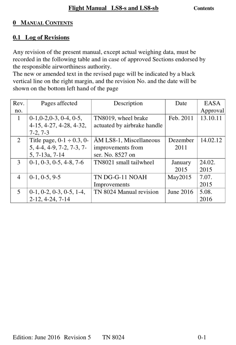
Maintenance Manual LS8-s and LS8-sb
Contents
Edition: June 2016 Rev. 6 TN 8024 0-1
0 Manual Contents
0.1 Log of Revisions
No. Page Description Date
1 0-1, 0-3, 0-6, 1-1,
1-6, 1-10, 1-11, 8-3
TN8019, wheel brake actuated by
airbrake handle.
Feb. 2011
2 Title page, 0-1, 0-3 ÷ 0-6,
0-9, 1-2, 1-6 ÷ 1-8, 1-21,
1-23, 1-28a, 4-1, 4-17,
6-4, 11-11, 9E4
ÄM LS8-1, Miscellaneous
improvements from
ser. No. 8527 on
December
2011
3 0-1, 0-3, 0-6, 1-15, 8-1 TN 8021
Small tailwheel
January
2015
4 0-1, 0-3, 0-5, 0-6, 0-10, 1-9,
4-11, 5-3, 5-4, 5-6, 6-1, 6-2,
8-1, 8-2
TN 8024
Manual revision, repair manual
June
2016
Maintenance Manual LS8-s and LS8-sb
Contents
Edition: June 2016 Rev. 6 TN 8024 0-3
0.2 List of Effective Pages
Chapter Page Edition Replaced Replaced Replaced
0 Title page April 2005
0-1 see log of revisions
0-2 see log of revisions
0-3 see log of revisions
0-4 see log of revisions
0-5 see log of revisions
0-6 see log of revisions
0-7 April 2005
0-8 April 2005
0-9 April 2005
Dec. 2011
0-10 April 2005
June 2016
0-11 April 2005
1 1-1 April 2005
Feb. 2011
1-2 April 2005
Dec. 2011
1-3 April 2005
1-4 April 2005
1-5 April 2005
1-6 April 2005
Feb. 2011 Dec. 2011
1-7 April 2005
Dec. 2011
1-8 April 2005
Dec. 2011
1-9 April 2005
June 2016
1-10 April 2005
Feb. 2011
1-11 April 2005
Feb. 2011
1-12 April 2005
1-13 April 2005
1-14 April 2005
1-15 April 2005
Jan. 2015
1-16 April 2005
1-17 April 2005
1-18 April 2005
1-19 April 2005
1-20 April 2005
Maintenance Manual LS8-s and LS8-sb
Contents
Edition: June 2016 Rev. 6 TN 8024 0-5
0.2 List of Effective Pages (continued)
Chapter Page Edition Replaced Replaced Replaced
4 4-10 April 2005
4-11 April 2005
June 2016
4-12 April 2005
4-13 April 2005
4-14 April 2005
4-15 April 2005
4-16 April 2005
4-17 April 2005
Dec. 2011
4-18 April 2005
4-19 April 2005
4-20 April 2005
5 5-1 April 2005
5-2 April 2005
5-3 April 2005
June 2016
5-4 April 2005
June 2016
5-5 April 2005
5-6 April 2005
June 2016
5-7 April 2005
5-8 April 2005
5-9 April 2005
5-10 April 2005
5-11 April 2005
5-12 April 2005
5-13 April 2005
5-14 April 2005
6 6-1 April 2005
June 2016
6-2 April 2005
June 2016
6-3 April 2005
6-4 April 2005
Dec. 2011
7 7-1 April 2005
Maintenance Manual LS8-s and LS8-sb
Contents
Edition: June 2016 Rev. 6 TN 8024 0-6
0.2 List of Effective Pages (continued)
Chapter Page Edition Edition Edition Edition
8 8-1 April 2005
Jan. 2015 June 2016
8-2 April 2005
June 2016
8-3 April 2005
Feb. 2011
9 9-1 April 2005
9-2 April 2005
10 10-1 April 2005
11 11-1 April 2005
11-2 April 2005
11-3 April 2005
11-4 April 2005
11-5 April 2005
11-6 April 2005
11-7 April 2005
11-8 April 2005
11-9 April 2005
11-10 April 2005
11-11 April 2005
Dec. 2011
11-12 April 2005
11-13 April 2005
11-14 April 2005
11-15 April 2005
9E4 28.11.08
Maintenance Manual LS8-s and LS8-sb
Contents
Edition: June 2016 Rev. 6 TN 8024 0-10
0.4 L
IFE
L
IMITED
P
ARTS
,
M
AINTENANCE
I
NSTRUCTIONS
0.4.1 Repairs
Repair or replace damaged parts prior to next flight. Follow the
instructions in the Repair Manual LS8.
Major repairs must be accomplished by an approved repair station or by an
approved mechanic rated for composite aircraft structure work in
accordance with DG repair methods.
Use only genuine spare parts.
For all aircraft under EASA regulations the following applies: According
to part 21, subpart M to accomplish major repairs an approved repair
instruction is required, see also TN DG-G-01 “Approved repair methods
according to EU Commission Regulation 1702/2003 part 21, subpart M”
0.4.2 Airframe structural Life limit
Maximum FRP structural life limit of sailplanes and powered sailplanes is
12000 hours of flight. To reach this limit, special inspections according to
chapter 2.4 of this manual at 3000, 6000, 9000 and beyond that at every
1000 hours of flight must be performed.
0.4.3 Life Limits of Equipment Items
a) Safety harness webbing life limited to 12 years after manufacture.
Multiple point buckle and brackets on condition (Wear, corrosion
etc.).
b) Further parts:
These parts as for instance wheels, gas struts, control system parts,
pins and bushes are not life limited, but may require exchange based
on condition (Wear, damage, corrosion).
Maintenance Manual LS8-s and LS8-sb
Systems
Edition: June 2016 Rev. 6 TN 8024 1-9
1.
S
YSTEM
D
ESCRIPTION AND
A
DJUSTMENT
D
ATA
(continued)
1.4 Elevator Control System (continued)
1.4.2 Deflections and Tolerances
Elevator: up 28° - 30°
down 22° - 26°
For easier checking, measured angles may be converted to mm / in
deflection values, using the actual local radius of the defined measuring
place. See also table below.
Limit values for elevator deflections in Millimetres/Inches
local radius 22°to 26° 28°to 30°
down up
mm in mm in mm in
67 2.638 26 to 30 1.024 to 1.181 32 to 35 1.260 to 1.378
68 2.677 26 to 31 1.024 to 1.220 33 to 35 1.299 to 1.378
69 2.717 26 to 31 1.024 to 1.220 33 to 36 1.299 to 1.417
70 2.756 27 to 31 1.063 to 1.220 34 to 36 1.339 to 1.417
71 2.795 27 to 32 1.063 to 1.260 34 to 37 1.339 to 1.457
72 2.835 27 to 32 1.063 to 1.260 35 to 37 1.378 to 1.457
1.4.3 Stops
Elevator stops at lower control stick end. Adjustment by use of two
10◦mm open end wrenches.
1.4.4 Elevator Rear Edge Play
Play should be measured with control stick fixed to neutral position.
Elevator : maximum 2.5 mm <0.1 in> at inner edge
Maintenance Manual LS8-s and LS8-sb
Instructions
Edition: June 2016 Rev. 6 TN 8024 4-11
4.5 Installation of Control Surfaces (continued)
Disassembly of Rudder
(1) disconnect rudder cables.
Attention: Don’t loose spacing casings.
Attention: Rudder cables may be drilled. If this is changed
unintentionally, neutral positions of rudder and pedals do no longer
correspond and must be realigned as detailed below.
(2) loosen nut at lower bearing (6mm thread, M6 LN 9348 or DIN 985-8zn,
width over flats 10mm) using a socket wrench, remember sequence and
position of washers.
(3) lift rudder upward from bearings.
Assembly of Rudder
(1) grease bearings according to lubrication schedule, see section 3.3.
(2) If need be, install new V-type internal seal, see section 4.6.
(3) lower rudder into bearings, do not use force !
(4) check radial play of upper bearing: maximum permissible radial play 0.5
mm <0.02 in>. If necessary renew brass bushing. Make sure, that non-
concentric position of bearing keeps relative position to direction of flight.
Bond bushing with for instance Loctite 72 b (672).
(5) connect rudder cables provisionally, do not forget to insert spacing casings
into thimbles.
(6) check rudder pedal alignment: with pedals in neutral position check if
rudder is neutral.
If rudder is deflected to one side, twist opposite cable counter-clockwise
(maximum 5 turns) until properly aligned.
Should more than 5 turns be necessary for alignment, exchange cables.
Caution: Never turn cables clockwise !
(7) place washers on cable connection bolts and tighten nuts M6 LN 9348 or
DIN 985-8zn, width over flats 10 mm, with maximum torque 6.4 Nm
(0.65 mkg, 4.623 ft lbs).
(8) set up washers at lower bearing as found during disassembly (normally:
recessed washer first, then large washer). Tighten nut (6 mm thread, LN
9348 or DIN 985-8zn, width over flats 10 mm) with maximum torque 6.4
Nm, (0.64 mkg, 4.623 ft lbs). After assembly the rudder should have
audible axial play, maximum axial play 1 mm (0.04 in), see section 1.5.
(9) if necessary, restore gap seals (convex plastic strip) on both sides, see
section 4.6.
Maintenance Manual LS8-s and LS8-sb
Weight and Balance
Edition: June 2016 Rev. 6 TN 8024 5-3
5.2 Calculation of Loading Limits
1. Determine Minimum Cockpit Load for 15 m wingspan and full and empty
tail fin tank version following procedure given in section 5.1 from table
“Empty Weight C.G. Position”, section 5.4 in <kg/mm> or <in/lbs>.
Minimum Cockpit Load for tail fin battery (3BR-199) removed (and
installed in baggage compartment, when required) decreases by 10 kg
<22 lbs>.
Finally resulting 4 different cockpit loads should be entered in the
following places:
a. in weighing report of inspection
b. in Flight Manual section 6.2
c. in cockpit placard under instrument panel cover
d. in cockpit on data placard
1. Minimum Cockpit Load for full tail fin tank with tail fin battery
2. Minimum Cockpit Load for empty tail fin tank with tail fin battery
3. Minimum Cockpit Load for full tail fin tank without tail fin battery
4. Minimum Cockpit Load for empty tail fin tank without tail fin battery
Maintenance Manual LS8-s and LS8-sb
Weight and Balance
Edition: June 2016 Rev. 6 TN 8024 5-4
5.2 Calculation of Loading Limits (continued)
2. Maximum approved Weight of Non-lifting Parts may vary, depending on
empty weight and empty weight C.G. position:
LS8-s: between 255 and 263 kg <562 to 580 lbs>
LS8-sb: between 280 and 288 kg <617 to 635 lbs>
In contrast to methods used up to now, maximum weight of non-lifting
parts can be determined in relation to empty weight and empty weight
C.G. position according to table in section 5.3. See also examples on end
of this section.
Maximum weight of Non-lifting Parts should be entered into weighing
report.
3. Determine Maximum approved Cockpit Load from table “Empty Weight
C.G. Position”, section 5.4 in <kg/mm> or <in/lbs>. Maximum Cockpit
Load normally should be 110 kg <242 lbs>, as given in empty weight
C.G. table. It may be lower due to trim conditions, excessive equipment or
repairs.
Calculate Maximum Cockpit Load on weighing report, see also examples
at end of this section.
Resulting Maximum Cockpit Load should be entered in the following
places:
a. in weighing report of inspection
b. in Flight Manual, section 6.2
c. on Data Placard in cockpit
4. Empty Weight (perhaps increased by weight of permanently fitted trim
ballast) should be entered in the following places:
a. in weighing report of inspection
b. in Flight Manual section 6.2 for calculation of maximum
permissible water ballast weight
5. Battery position during weighing should be entered in the following
places:
a. in weighing report and equipment list of inspection
b. in section 6.2 of Flight Manual
For permanent installation of trim ballast weights, see Maintenance
Manual section 4.15.
Form for Weighing Report, see Maintenance Manual section 11.
Maintenance Manual LS8-s and LS8-sb
Weight and Balance
Edition: June 2016 Rev. 6 TN 8024 5-6
5.2 Calculation of Loading Limits (continued)
Example for entry in Flight Manual section 6.2:
LS8-s LS8-sb
Wing span [m] 15 18 15 18
Empty Mass
[kg] /
[lbs]
273 282 273 282
C.G. position
[mm] /
[in]
665 665
Max. Cockpit Load
[kg] /
[lbs]
110 110
Tail tank
full (+)
[kg] /
[lbs]
120 140
with tail-
battery Tail tank
empty (+)
[kg] /
[lbs]
780 80
Tail tank
full (+)
[kg] /
[lbs]
110 130
Minimum Cockpit
Loadg
without tail-
battery Tail tank
empty (+)
[kg] /
[lbs]
70 70
front
[kg] /
[
lbs
]
--- ---
Perm.
fixed Trim
mass
rear
[kg] /
[
lbs
]
--- ---
Seat
[No.] 1 1
Baggage comp.
[No.] 0 0
Batteries
installed
Vert. tail fin
[No.]
1 1
Date / Inspector 18.08.2005
GS
18.08.2005
GS
The discrepancy between Maximum Cockpit Load of 110 kg <242 lbs> and
Minimum Cockpit Load of 140 kg <309 lbs> (for LS8-sb) with tail fin tank
full and tail fin battery indicates, that before each take off the installation
position of the tail fin battery must be checked and a functional check for
the tail fin tank valve is required to make sure that no unintended amount
of water remains in the fin tank.
To check the valve place tail tank filling adapter into the tank outlet and
open the cockpit lever. If air cannot be blown into the tank, the valve is not
functioning properly (for instance frozen solid or operating cable
fractured).
Maintenance Manual LS8-s and LS8-sb
Instruments and. Equipment
Edition: June 2016 Rev. 6 TN 8024 6-1
6. Instruments- and Equipment List (Master Equipment List)
Maximum mass of all Instrument Panel Installations max. 6.7 kg <14.8 lbs>.
6.1 Airspeed Indicator
Manufacturer Type TCDS No.
W
inte
r
6FMS-4 (Diameter 80mm)
0-300 km/h Art.No. 6421-499
0-160 kts Art.No. 6423-499
6FMS-5 in km/h
TS 10.210/15
W
inte
r
7FMS-4 (Diameter 58mm)
0-300 km/h Art.No. 7421-499
0-160 kts Art.No. 7423-499
7FMS-42
TS 10.210/19
Thommen 5A58() range 300 km/h
P
ZL PR-400 S-A in km/h
or other Airspeed indicators approved according to TSO, JTSO or ETSO for
use in aircraft or similar FAA approved airspeed indicators to meet TSO C2
reading to 300 km/h <160 Kt., 180 mph> may be used. Maximum instrument
error ±2%. Colour marking must be according to Flight Manual section 2-3.
6.2 Altimeter
Manufacturer Type TCDS No.
Winter 4 FGH 10 (Diameter 80mm)
1000-10000m Art.No. 4110
3000-30000ft Art.No. 4330
TS 10.220/46
Winter 4 FGH 20 (Diameter 58mm)
1000-10000m Art.No. 4220
TS 10.220/47
Winter 4 FGH 20 (Diameter 58mm)
1000-20000ft Art.No. 4550
TS 10.220/48
PZL W-12S in m
or other Altimeters approved according to TSO, JTSO or ETSO for use in
aircraft; one turn of dial max. 1000 m or 3000 ft. A similar FAA approved
altimeter to meet TSO C10 with a range of approximately 33000 ft and a
mercury or millibar or hektopascal subscale may be used. When an altimeter of
up to 20000 ft only is being used, a placard must be near the altimeter stating:
Maximum flying altitude 20000 ft. See also Flight Manual section 2.10.
Maintenance Manual LS8-s and LS8-sb
Instruments and. Equipment
Edition: June 2016 Rev. 6 TN 8024 6-2
6.3 Seat Belt Harness (with multiple point buckles)
Manufacturer Type TCDS No.
Schroth 4-01-0.104 (Lap belt and
shoulder strap) 40.073/11
Gadringer Lap belt 5202 40.070/32
Shoulder strap 2700 40.071/05
6.4 Compass
Manufacturer Type TCDS No.
Ludolph FK 16, FK 5, FK 10 10.410/3
Airpath C 2300, C 2400 TS 10.220/47
PZL BS1, KJ-13A FD 19/77
Bohli 46 MFK 1 Not approved, only as
additional system
6.5 UHF – Transmitter and Receiver
Manufacturer Type TCDS No.
Dittel FSG-40 S 10.911/45
FSG-50 10.911/71
FSG-60 M 10.911/72
FSG-70,71 M 10.911/81
FSG-90 10.911/98JTSO
FSG 2T LBA.0.10.911/103JTSO
Becker AR 3201-(1) 10.911/76
AR 2008/25 (A) 10.911/48
AR 4201 JTSO-2C37 D, ED-23A
AR 6201 EASA.210.1249
Avionik Dittel ATR 720 A 10.911/74
ATR 720 C 10.911/83
ATR 600 LBA.0.10.911/106JTSO
ATR 500 LBA.0.10.911/113JTSO
ATR 833 EASA.210.0193
Dittel Avionik KRT2 EASA.210.10038036
or other radios approved according to TSO, JTSO or ETSO for use in aircraft.
Maintenance Manual LS8-s and LS8-sb
Placards
Edition: June 2016 Rev. 4 TN 8024 8-1
8. Markings and Placards
Under instrument panel cover
At underside of instrument panel
Tyre pressure
3.5 bar on right
(51 psi) landing gear door
Tyre pressure above tail wheel,
2.5 - 3.5 bar when fitted
(36 to 51 psi) xx= variant –s or –sb At right cockpit wall
at Baggage Compartment
Maximum Baggage weight 5 kg (11 lbs) Ball of bearing at forward horizontal tail
(For soft items only) must be fixed attachment on vertical tail fin
DG-Flugzeugbau GmbH
TYPE LS8-s .
TCDS- No. A.047 .
Serial Number 8xxx .
Reg. Signs D-xxxx .
DG-Flugzeugbau GmbH
TYPE LS8-sb .
TCDS- No. A.047 .
Serial Number 8xxx .
Reg. Signs D-xxxx .
Type placard at main bulkhead
Tyre Pressure above tailwheel
6,2 bar/90 psi small tailwheel according to TN 8021, if installed
DG Flugzeugbau GmbH
Type: LS8-xx Serial No.:_______
Data Placard
Airspeed Limits: km/h Kt MPH.
Winch launch/Auto tow 140 76 87
Aero tow 195 105 121
In rough air 195 105 121
Never exceed (VNE) 280 151 174
m ft kg lbs
Max. Take-off Mass *) 15 42 525 1157
Max. Take-off Mass *): 18 59 575 1267
*) including water ballast
Aerobatic manoeuvres not approved
Weight Limitations
Maximum Cockpit Load ....max.______kg/lbs
Minimum Cockpit Load
with tail battery, tail tank full min. ______kg/lbs
with tail battery, tail tank empty min. ______kg/lbs
without tail battery, tail tank full min _____kg/lbs
without tail battery, tail tank empty min._____kg/lbs
Lighter pilots must compensate lack of weight as
suggested in Flight Manual
MINIMUM COCKPIT LOAD: kg / lbs
with tail battery, tail tank full min. ________
with tail battery, tail tank empty min. ________
without tail battery, tail tank full min. ________
without tail battery, tail tank empty min. ________
LS8-s and -sb Checklist
This sailplane must be operated in
compliance with operating limitations
stated in the form of markings,
placards and EASA approved Flight
Manual.
1. Main pins secured?
2. Elevator secured?
3. Winglets secured?
4. Check controls
5. Tail fin valve operation checked?
6. When using water ballast, then
always in wing and tail!
7. Check loading conditions
8. Check tail dolly removed?
9. Fasten seat belt harness
10. Fasten parachute and connect
parachute static line
11. Lock air brakes
12. Check trim position
13. Check release system
14. Lock canopy
Maintenance Manual LS8-s and LS8-sb
Placards
Edition: June 2016 Rev. 4 TN 8024 8-2
8. Markings and Placards (continued)
When using a battery in the
vertical tail fin. Minimum
Cockpit Load must be
redetermined by weighing
Use vertical tail fin battery only
with main fuse at battery
at vertical tail fin battery cover
Canopy Emergency Release: open left side normally,
pull right side with approx.15 kg/33 lbs force to stop
at right canopy frame
Altitude related
Never Exceed Speed
km/h
Altitude related Never
Exceed Speed
km/h
Kt.
mph
Up to 2000 m MSL 280 Up to 6500 ft MSL 280 151 174
Up to 3000 m MSL 266 Up to 9800 ft MSL 266 144 165
Up to 4000 m MSL 253 Up to 13100 ft MSL 253 136 157
Up to 6000 m MSL 227 Up to 19700 ft MSL 227 122 141
Up to 8000 m MSL 202 Up to 26200 ft MSL 202 109 126
Up to 10000 m MSL 179 Up to 32800 ft MSL 179 97 111
Up to 12000 m MSL 156 Up to 39400 ft MSL 156 84 97
On panel near airspeed indicator, On panel near airspeed indicator
for countries operating with metric
units only.

Other manuals for LS8-s

1

This manual suits for next models

1

Other DG Flugzeugbau Aircraft manuals

DG Flugzeugbau LS8 Series User manual

DG Flugzeugbau

DG Flugzeugbau LS8 Series User manual

DG Flugzeugbau DG-1000T User manual

DG Flugzeugbau

DG Flugzeugbau DG-1000T User manual

DG Flugzeugbau LS8 Series Technical specifications

DG Flugzeugbau

DG Flugzeugbau LS8 Series Technical specifications

DG Flugzeugbau DG-800A User manual

DG Flugzeugbau

DG Flugzeugbau DG-800A User manual

DG Flugzeugbau LS8-s Technical specifications

DG Flugzeugbau

DG Flugzeugbau LS8-s Technical specifications

DG Flugzeugbau DG-800S Technical specifications

DG Flugzeugbau

DG Flugzeugbau DG-800S Technical specifications

DG Flugzeugbau DG-500M User manual

DG Flugzeugbau

DG Flugzeugbau DG-500M User manual

DG Flugzeugbau DG-1000T User manual

DG Flugzeugbau

DG Flugzeugbau DG-1000T User manual

DG Flugzeugbau DG-1000 Operating instructions

DG Flugzeugbau

DG Flugzeugbau DG-1000 Operating instructions

DG Flugzeugbau LS8 Series User manual

DG Flugzeugbau

DG Flugzeugbau LS8 Series User manual

DG Flugzeugbau DG-1000 Technical specifications

DG Flugzeugbau

DG Flugzeugbau DG-1000 Technical specifications

DG Flugzeugbau LS10-s User manual

DG Flugzeugbau

DG Flugzeugbau LS10-s User manual

DG Flugzeugbau DG-1000 Technical specifications

DG Flugzeugbau

DG Flugzeugbau DG-1000 Technical specifications

DG Flugzeugbau DG-500MB Technical specifications

DG Flugzeugbau

DG Flugzeugbau DG-500MB Technical specifications

DG Flugzeugbau LS10-s Technical specifications

DG Flugzeugbau

DG Flugzeugbau LS10-s Technical specifications

DG Flugzeugbau DG-800A Technical specifications

DG Flugzeugbau

DG Flugzeugbau DG-800A Technical specifications

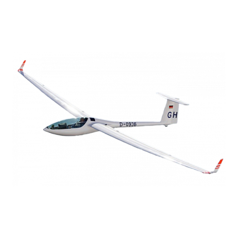
DG Flugzeugbau DG-500 ELAN Orion Technical specifications
DG Flugzeugbau

DG Flugzeugbau DG-500 ELAN Orion Technical specifications

DG Flugzeugbau DG-800B Technical specifications

DG Flugzeugbau

DG Flugzeugbau DG-800B Technical specifications

DG Flugzeugbau DG-1000S Technical specifications

DG Flugzeugbau

DG Flugzeugbau DG-1000S Technical specifications

DG Flugzeugbau DG-1001M Technical specifications

DG Flugzeugbau

DG Flugzeugbau DG-1001M Technical specifications

DG Flugzeugbau DG-500 ELAN Orion Technical specifications

DG Flugzeugbau

DG Flugzeugbau DG-500 ELAN Orion Technical specifications

DG Flugzeugbau DG-1000M Technical specifications

DG Flugzeugbau

DG Flugzeugbau DG-1000M Technical specifications

DG Flugzeugbau DG-800S Operating instructions

DG Flugzeugbau

DG Flugzeugbau DG-800S Operating instructions

DG Flugzeugbau DG-500 ELAN Orion Technical specifications

DG Flugzeugbau

DG Flugzeugbau DG-500 ELAN Orion Technical specifications

Popular Aircraft manuals by other brands
SC Escort-2 manual

SC

SC Escort-2 manual

ICON A5 Maintenance manual

ICON

ICON A5 Maintenance manual

Flow Paragliders Spectra manual

Flow Paragliders

Flow Paragliders Spectra manual

Piper ARCHER III Pilot operating handbook

Piper

Piper ARCHER III Pilot operating handbook

Lancair Legacy Fixed Gear Supplement

Lancair

Lancair Legacy Fixed Gear Supplement

ICARO paragliders TWICE TE manual

ICARO paragliders

ICARO paragliders TWICE TE manual

NIVIUK GLIDERS IKUMA 2 P user manual

NIVIUK GLIDERS

NIVIUK GLIDERS IKUMA 2 P user manual

AEROPRAKT AEROPRAKT-22L2 Pilot operating handbook

AEROPRAKT

AEROPRAKT AEROPRAKT-22L2 Pilot operating handbook

Ozone De-Power manual

Ozone

Ozone De-Power manual

Bruce Goldsmith Design WASP Ownersmanual

Bruce Goldsmith Design

Bruce Goldsmith Design WASP Ownersmanual

Skywalk TEQUILA6 Pro Guide

Skywalk

Skywalk TEQUILA6 Pro Guide

PZL Bielsko SZD-50-3 PUCHACZ Flight manual

PZL Bielsko

PZL Bielsko SZD-50-3 PUCHACZ Flight manual

WINDTECH Quarx2 manual

WINDTECH

WINDTECH Quarx2 manual

McDonnell Douglas 369H Series Appendix

McDonnell Douglas

McDonnell Douglas 369H Series Appendix

Boeing 747-400 Operation manual

Boeing

Boeing 747-400 Operation manual

Magni Gyro M-16 C Flight manual

Magni Gyro

Magni Gyro M-16 C Flight manual

Cabrinha Race installation guide

Cabrinha

Cabrinha Race installation guide

Cessna 150G owner's manual

Cessna

Cessna 150G owner's manual

manuals.online logo
manuals.online logoBrands
  • About & Mission
  • Contact us
  • Privacy Policy
  • Terms and Conditions

Copyright 2025 Manuals.Online. All Rights Reserved.