manuals.online logo
Brands
  1. Home
  2. •
  3. Brands
  4. •
  5. DG Flugzeugbau
  6. •
  7. Aircraft
  8. •
  9. DG Flugzeugbau LS10-s Technical specifications

DG Flugzeugbau LS10-s Technical specifications

Flight manual LS10-s,-st
Issued: December 2011 TN LS10-02 0.1
0Revisions
0.1 Record of revisions
Any revision of the present manual, except actual weighing data, must be
recorded in the following table and in case of approved sections endorsed by the
responsible airworthiness authority.
The new or amended text in the revised page will be indicated by a black
vertical line in the right hand margin, and the Revision No. and the date will be
shown on the bottom left hand of the page.
Rev.
No.
Affected
Pages/
section
Description Issue
Date
EASA
Approval
Date
Inserted
Date
Signature
1
0.1, 0.3 ÷
0.6, 2.4, 2.6,
4.2, 4.3,
6.13, 6.14,
7.2,
7.33 ÷ 7.35
Manual revision
TN LS10-02
December
2011
February
17. 2012
Flight manual LS10-s,-st
Issued: December 2011 TN LS10-02 0.3
0.2 List of effective pages
Section page issued replaced/ replaced/
0 0.0 October 2009
0.1 see manual amendments
0.2 "
0.3 "
0.4 "
0.5 "
0.6 "
0.7 October 2009
1 1.1 October 2009
1.2 "
1.3 "
1.4 "
1.5 "
1.6 "
2 App. 2.1 October 2009
" 2.2 "
" 2.3 "
" 2.4 " December 11
" 2.5 "
" 2.6 " December 11
" 2.7 "
" 2.8 "
" 2.9 "
" 2.10 "
" 2.11 "
" 2.12 "
" 2.13 "
" 2.14 "
3 " 3.1 October 2009
" 3.2 "
" 3.3 "
" 3.4 "
" 3.5 "
" 3.6 "
" 3.7 "
" 3.8 "
" 3.9 "
Flight manual LS10-s,-st
Issued: December 2011 TN LS10-02 0.4
0.2 List of effective pages (cont.)
Section Page issued replaced/ replaced/
4 App. 4.1 October 2009
" 4.2 " December 11
" 4.3 " December 11
" 4.4 "
" 4.5 "
" 4.6 "
" 4.7 "
" 4.8 "
" 4.9 "
" 4.10 "
" 4.11 "
" 4.12 "
" 4.13 "
" 4.14 "
" 4.15 "
" 4.16 "
" 4.17 "
" 4.18 "
" 4.19 "
" 4.20 "
" 4.21 "
" 4.22 "
" 4.23 "
" 4.24 "
" 4.25 "
" 4.26 "
" 4.27 "
" 4.28 "
" 4.29 "
5 " 5.1 October 2009
" 5.2 "
" 5.3 "
App. 5.4 "
5.5 "
5.6 "
5.7 "
5.8 "
5.9 "
5.10 "
5.11 "
5.12 "
Flight manual LS10-s,-st
Issued: December 2011 TN LS10-02 0.5
0.2 List of effective pages (cont.)
Section Page issued replaced/ replaced/
6 6.1 October 2009
6.2 "
6.3 "
6.4 "
6.5 "
6.6 "
6.7 "
6.8 "
6.9 "
6.10 "
6.11 "
6.12 "
6.13 " December 11
6.14 " December 11
7 7.1 October 2009
7.2 " December 11
7.3 "
7.4 "
7.5 "
7.6 "
7.7 "
7.8 "
7.9 "
7.10 "
7.11 "
7.12 "
7.13 "
7.14 "
7.15 "
7.16 "
7.17 "
7.18 "
7.19 "
7.20 "
7.21 "
7.22 "
7.23 "
7.24 "
Flight manual LS10-s,-st
Issued: December 2011 TN LS10-02 0.6
0.2 List of effective pages (cont.)
Section page issued replaced/ replaced/
7.25 "
7.26 "
7.27 "
7.28 "
7.29 "
7.30 "
7.31 "
7.32 "
7.33 " December 11
7.34 " December 11
7.35 " December 11
7.36 "
8 8.1 October 2009
8.2 "
8.3 "
8.4 "
8.5 "
9 9.1 October 2009
9.2 "
9.3 "
9.4 "
9.5 "
Flight manual LS10-s,-st
Issued: December 2011 TN LS10-02 2.4
EASA app.
2.3 Airspeed Indicator Markings
Airspeed indicator markings and their colour code significance are shown below.
Marking
(IAS) value or
range
km/h (kts)
Significance
White Arc
88 - 200
(47,5 - 108)
Positive Flap Operating
Range
(lower limit is maximum weight
1.1 VSO in landing configuration.
Upper limit is maximum speed
permissible with flaps extended
positive +2, +1)
Green Arc
97 - 200
(52 - 108)
Normal Operating Range
(Lower limit is 1.1 VS1 at
maximum weight and most
forward c.g. with flaps neutral.
Upper limit is rough air speed.)
Yellow Arc
200 - 280
(108 - 151)
Manoeuvres must be conducted
with caution and only in smooth
air.
Red Line
280
(151)
Maximum speed for all
operations.
L
150
( 81)
Max. speed for landing
configuration L
Yellow
Triangle
100
(54)
Approach speed at maximum
weight without water ballast
only LS10-st
Blue line
95
( 51)
Speed of best climb Vy, (only for
LS10-st)
Flight manual LS10-s,-st
Issued: December 2011 TN LS10-02 2.6
EASA app.
Fuel quantity indicator:
On left hand upper side of the DEI-NT display, digital indication with 2
digits. Limitation data for the non usable amount of fuel printed above the
display:
Max Fuel capacity 12l
red 0.3 l
When a fuel quantity of approx. 2 Litres is reached a full screen warning
“Low Fuel” appears, when this warning has been confirmed (by pushing
the selector knob at the right hand side of the display) the fuel display will
keep blinking.
When reaching the non usable amount of fuel “R” is displayed and will
keep blinking.
2.6 Fuel (only LS10-st)
Fuel capacity:
Fuselage tank:
total: 12 l (3.20 US gal.)
Non usable amount of fuel:0.3 l (0.08 US gal.)
Usable amount of fuel: 11,7 l (3.09 US gal)
Approved fuel grades:
Automobile super gasoline min. 95 octane (ROZ) (RON) leaded or
unleaded
or: AVGAS 100 LL (only if super gasoline is not available)
or: mix 50% AVGAS 100LL with 50% car gasoline min. 92 octane
(ROZ) (RON)
mixed with self-mixing Super quality two stroke oil - specification TSC 3 or
API TC or JASO FC or higher quality. Mixing ratio 1:40
Note: The SOLO company recommends the following oil types: CASTROL
Actevo 2T or Castrol Super Two stroke.
Flight manual LS10-s,-st
Issued: December 2011 TN LS10-02 4.2
EASA app.
4.1 Introduction
Section 4 provides checklists and amplified procedures for the conduct of normal
operation. Normal procedures associated with optional systems can be found in
section 9.
4.2 Rigging and derigging, filling the watertanks, refuelling
4.2.1 Rigging
1. Execute the inspection prior to rigging according to section 4.3 A.
2. Clean and grease all pins and bushes and all 4 automatic control system
connectors.
3. Open the canopy.
4. Set the airbrake handle to the forward stop and control stick and wingflap
handle to neutral.
Always rig inner wings without 15 m or 18 m tips.
With a helper on the wingtip, push the left wing into place, then the right
wing.
Check for correct dihedral. The flaperons should be held at neutral for
rigging, airbrakes locked. All controls will hook up automatically.
Caution: Make sure that the wing trailing edge is at the same height as its
counterpart at the fuselage before the controls hook up. Otherwise a ball bearing
of a control hook up bellcrank (mounted at the wing root) may knock against
the fuselage-side control and will be damaged.
Sight through the wing main pin bushings to determine alignment. Push the
main pins in as far as possible. Turn one handle after the other up to the
fuselage wall, while pulling out the white securing knob, then release the
knob back to its locked position. Check the securing.
5. Insert the wing tip extensions (18 m) into the wing.
Press in the locking pin with your finger.
Insert the wing tip until the flaperon connecting pins start to slide into the
centre-flaperon bushes.
Strike firmly with the palm of your hand on to the wing tip to lock the wing
tip extension.
The rigging of the 15 m wingtips (Option) has to be done in the same
manner as the wing tip extensions.
6. Check if you are safe to fly with the fin battery (see Data Placard in cockpit
or entries in section 6). Insert the battery into place. Connect battery to the
aircraft electric system and check operation.
Flight manual LS10-s,-st
Issued: December 2011 TN LS10-02 4.3
EASA app.
7. Rigging of the horizontal tailplane
Check the glued joint of the spherical insert in the eye-bolt in the front
horizontal tailplane attachment. Swivel movement is not allowed!
Warning: If this insert is loose, flights are strictly prohibited. Contact the aircraft
manufacturer.
Install the horizontal tailplane and fix it by turning the slotted nut mounted
on the rear attachment (using supplied key or suitable coin) until there is no
more free play and the red marking on the main attachment bracket is no
longer visible via the hole in the upper shell.
8. Install total energy tube, secure against rotating using tape.
9. Mount all necessary equipment in the baggage compartment. Safely secure
all items.
10. Connect automatic parachute ripcord at red marked position at main
bulkhead. Wrap cord around the lift pin tube.
11. Tape the gaps of the wing-fuselage junctions, the wing joints and the
horizontal stabilizer.
12. Execute a positive control check, one helper is needed to hold firmly the
control surfaces.
Only LS10-st
13. Pull off the fuel vent surge bottle from the fuel vent line (bottom side of the
fuselage).
14. Open fuel shut off valve.
4.2.2 De-Rigging:
Derigging follows the reverse of rigging.
Waterballast must be dumped first.
Airbrakes should be locked.
Note: It is also possible to de-rig with the airbrakes not locked. In such case you
have to make sure that the airbrakes won’t be damaged in the trailer in case they
extend due to vibrations. It is not necessary to lock the airbrakes for rigging
Disassembling the wing tips:
Use a 6 mm diameter pin for pressing in the locking pin on the wing’s upper
surface. Pull out the wing tips.
Only LS10-st
Push the fuel vent surge bottle onto the fuel vent line (bottom side of the
fuselage).
Close fuel shut-off valve.
Note: During road-transport with full fuel tank fuel may spill via the carburettors
or via the ventilation line. To avoid this the fuel shut-off valve should be
closed during de-rigging and the fuel vent surge bottle installed.
Flight Manual LS10-s,-st
Issued: December 2011 TN LS10-02 6.13
Table of C.G. positions for various items of equipment:
Item mass C.G. behind
datum
kg lbs m ft
1 Battery in front of control stick
*)
2,5 5,5 -1,05 -3,44
Battery in baggage compartment
4BR-255/2
2,5 5,5 0,185 0,61
Battery in the fin 3BR-199 2,6 5,7 4,308 14,13
Water in LH (System No.1)-
(forward) fin tank - up to
3,9 8,6 4 13,12
Water in RH (System No. 2)-
(rear) fin tank - up to
4,6 10,1 4,16 13,65
Water in outer wing tank
(System No.1) - up to
30,0 66,1 0,189 0,62
Water in the centre wing tank
(System No. 1)- up to
50,0 110,2 0,189 0,62
Water in the inner wing tank
(System No. 2) - up to
110,0 242,5 0,196 0,64
Powerplant 26,5 58,4 1,05 3,44
Empty fuel tank 1,5 3,3 0,38 1,25
Fuel in main tank max. 7,0 15,4 0,38 1,25
Trim weight rear fuselage 4R8-
109
2,5 5,5 4,383 14,38
Trim weight in front support
4R8-108
2,45 5,4 -1,69 -5,54
Heavy tail wheel (P/N.: S27) **) 3,4 6,6 4,314 14,15
*) usually 2 batteries are installed
**) 3.0kg (6.6 lbs) more than standard tail wheel with plastic hub S23
(mass of plastic hub S23 with tyre= 0,9 kg (1.98 lbs.))
Flight Manual LS10-s,-st
Issued: December 2011 TN LS10-02 6.14
Rule of thumb:
Installation of 1 trim ballast weight (2.45 kg, 5.4 lbs) in front support.............
...................................... reduces Minimum Cockpit Load by 5,5 kg / 12 lbs
Installation of 1 Battery (2.5 kg, 5.5 lbs) in front of the control stick.......
..................................... reduces Minimum Cockpit Load by 3,9 kg / 8.6 lbs
Installation of battery in the fin (2.6 kg, 5.7 lbs) .......................................
...............................increases Minimum Cockpit Load by 11,2 kg / 24.6 lbs
Installation of heavy tailwheel (mass difference to standard tail wheel 3 kg
6.6 lbs.)..................increases Minimum Cockpit Load by 12,9 kg / 28.5 lbs
Installation of trim weight rear fuselage (2,5 kg, 5.5 lbs.)
......................................increases Minimum Cockpit Load by 11kg / 24 lbs
Warning: In case of doubt: Mass and Balance must be determined by
reweighing the sailplane
C.G. Shift due to extension of the engine
XS2 = XS1 – 2,3/W W = total mass (kg)
XS2 = C.G. position with
engine extended (m)
XS1 = C.G. position with
engine retracted (m)
Flight Manual LS10-s,-st
Issued: December 2011TNLS10-027.2
7.1 Introduction
Section 7 describes the operation of the sailplane including its systems.
M.M. = Maintenance manual
Refer to section 9 "Supplements" for details of optional systems and
equipment.
7.2 Airframe
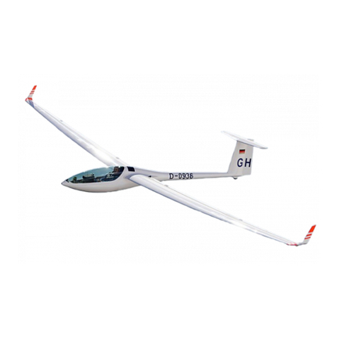
The LS10-s is a single-seater high performance glider.
The LS10-st is a self-sustainer single-seater high performance motorglider
with retractable powerplant.
18 m wingspan with wing parting at y=7 m, wingtips for 15m span optional.
Construction
Wings CFRP-foam-sandwich-shell with
CFRP-roving spar caps
Flaperons CFRP-foam-sandwich-shell
Rudder GFRP-foam sandwich-shell
Horizontal stabilizer GFRP/ AFRP-foam sandwich-shell
Elevator AFRP -skin
Fuselage CFRP-GFRP-shell
Canopy
Large single piece canopy, hinged at the front (nose) and supported by a gas
strut. Canopy is made of Plexiglas GS clear “GS 241“ or optionally green “GS
green 2942” or optionally blue “GS blue 2928“.
Canopy glass glued onto a GFRP frame
Tailplane
T-Tail with conventional stabilizer-elevator and spring trim.
Colours
Airframe: white
registration numbers: grey RAL 7001 or red RAL 3020
blue RAL 5012 or green RAL 6001
Anti collision paint
Approved colours: red, fluorescent red or orange
Approved areas:
1. Rudder: may be painted completely
2. Horizontal tail: paint only the stabilizer and only up to 200 mm from the
tips
3. Wing Sections: the inner wing shall not be painted
4. 15 m tips: can be painted entirely
5. 18 m wing tips: paint only the wing and not the ailerons, no more than 400
mm from the tips
Note: 3M mirror foil may be applied to all parts of the airframe
Flight Manual LS10-s,-st
Issued: December 2011 TN LS10-02 7.33
7.15 Pitot-/Static pressure system
1 Multi Probe : Pitot-/Static-/TE pressure port
2 Pitot pressure port at fuselage nose.
3 Static pressure port for airspeed indicator and altimeter – forward fuselage
sides.
4, Vacuum Bottles.
AASI ECapacity bottles for variometers
BAltimeter GVariometer switch (Option):
CVariometer TE (Soaring) / static ( Engine operstion)
DElectrical Variometer (switch shown in „SOARING“ position
Colours of instrument lines:
1Multi Probe:
Pitot clear
Static red
TE green
2Front total pressure yellow
3Static pressure front blue (for ASI and altimeter only!)
4Variometer capacity bottles clear Ø8 mm (0,315 in)
Note: To preserve the sealing-rings inside the holder for the Multi Probe, the end
of the probe should be greased with e.g. Vaseline from time to time.
Flight Manual LS10-s,-st
Issued: December 2011 TNLS10-027.34
7.16 Canopy
Canopy emergency release
Canopy locks :pull both red handles to stops
- Right handle operates emergency canopy jettison, therefore
it has longer travel than left handle.
Pull with more than 15kg / 33lbs!
- Hand force increases for emergency jettison travel to avoid
unintentional jettison during normal operation.
Canopy: Push off canopy using both red handles
- The gas strut which lifts the instrument panel assists the
canopy jettison.
LS-latch (Röger hook): This device is installed at the upper rear end of the
canopy and serves as hinge point for the canopy after
emergency release..
Checking the emergency release on the ground and removal of canopy:
One person must sit in the cockpit and one person must hold the canopy at the
front end.
1. With canopy closed pull on both red handles to bring them to the open
position. Thereafter pull strongly on the right hand handle to jettison the
canopy.
2. As soon as the canopy is lifted by the instrument panel support the person
at the front end must hold the canopy so that it will not be lifted more than
approx. 3 cm ( 1 in.).
3. The person in the cockpit must then lift the canopy at the rear end to
disengage the LS-latch (Röger hook).
4. Open the canopy simultaneously with the movement of the instrument
panel.
5. If you want to remove the canopy from the glider disconnect cables, if
equipment like a GPS antenna is installed on the glare shield.
Reinstalling the canopy:
Two people are required to operate and hold the canopy
1. Connect all cables, if equipment like a GPS antenna is installed on the
glareshield
2. Bring the locking lever at the canopy into the open position (rotate
clockwise)
3. Place the canopy on the instrument panel support. Move the locking pin
with the knurled knob (at the instrument panel support) upwards and move
the locking pin through the release cut-out in the canopy. Rotate the
locking lever at the canopy counter-clockwise until the canopy is locked.
Both elements are accessible from the fuselage nose with an open canopy.
Flight Manual LS10-s,-st
Issued: December 2011 TNLS10-027.35
Caution: If you pulled the emergency release inadvertently while opening the
canopy you should hold down the canopy at the emergency release handle.
Then lift the canopy at the rear end with your left hand to disengage the Röger
hook. Then open the canopy simultaneously with the movement of the
instrument panel and take off the canopy. If you don’t follow this procedure
the canopy might be damaged by the instrument panel.
7.17 Miscellaneous equipment (Options)
7.17.1 Removable Ballast
The installation of one trim ballast weight 4R8-108 2.45 kg (5.4 lbs) at the
holder in front of the rudder pedal assy decreases the necessary pilot mass by
approximately 5,5 kg (12 lbs). (max. 3 front trim weights can be
installed).Further data regarding Cockpit Load see section 6.
7.17.2 Oxygen system
A fiberglas receptacle is installed in the left hand side of the main bulkhead for
3 or 4 Litre oxygen bottles of 100 mm (3.94 in) in diameter. Bottles must be
fixed with the designated clamp (P/N.: 4R8-41c)
After permanent installation of an oxygen system according to its
manufacturer instructions by an adequately licensed maintenance/ repair shop,
the sailplane including oxygen system must be inspected (Weight and Balance,
Loading Instructions).
When using a removable oxygen unit, its weight must be counted as cockpit
load.
7.17.3 Emergency Locator Transmitter (ELT)
ELT: The ELT may be installed on the holder 9R96 according to installation
plan 9EP24 attached to the Maintenance Manual and according to the ELT
manufacturer’s instructions.
The designated place is the moulding on the RH side of the landing gear box
below the baggage compartment. As the ELT is not accessible in flight an
ELT remote control must be installed.
The gain access to the on-off switch of the ELT e.g. for switching off the
ELT for ground transport, the radio speaker plate must be mounted on an
access door according to drawing 4R07-091.
Caution: Antenna installation is only certified according to installation plan
9EP22 attached to the MM.
After installation, a functional test and inspection must be performed by a
licensed inspector.
The ELT must be switched off during road transport.
With ELT installed onto holder 9R96, the installation of an additional battery see
AFM sect. 7.17.4 is not possible.

Other manuals for LS10-s

1

This manual suits for next models

1

Other DG Flugzeugbau Aircraft manuals

DG Flugzeugbau LS8-st User manual

DG Flugzeugbau

DG Flugzeugbau LS8-st User manual

DG Flugzeugbau LS10-s User manual

DG Flugzeugbau

DG Flugzeugbau LS10-s User manual

DG Flugzeugbau DG-1000 Technical specifications

DG Flugzeugbau

DG Flugzeugbau DG-1000 Technical specifications

DG Flugzeugbau LS8-s User manual

DG Flugzeugbau

DG Flugzeugbau LS8-s User manual

DG Flugzeugbau DG200 Technical specifications

DG Flugzeugbau

DG Flugzeugbau DG200 Technical specifications

DG Flugzeugbau DG-800S Operating instructions

DG Flugzeugbau

DG Flugzeugbau DG-800S Operating instructions

DG Flugzeugbau LS8 Series Technical specifications

DG Flugzeugbau

DG Flugzeugbau LS8 Series Technical specifications

DG Flugzeugbau DG-800S Technical specifications

DG Flugzeugbau

DG Flugzeugbau DG-800S Technical specifications

DG Flugzeugbau DG-500MB Technical specifications

DG Flugzeugbau

DG Flugzeugbau DG-500MB Technical specifications

DG Flugzeugbau DG-1000 Operating instructions

DG Flugzeugbau

DG Flugzeugbau DG-1000 Operating instructions

DG Flugzeugbau LS8 Series User manual

DG Flugzeugbau

DG Flugzeugbau LS8 Series User manual

DG Flugzeugbau DG-500 ELAN Orion Technical specifications

DG Flugzeugbau

DG Flugzeugbau DG-500 ELAN Orion Technical specifications

DG Flugzeugbau DG-800A Technical specifications

DG Flugzeugbau

DG Flugzeugbau DG-800A Technical specifications

DG Flugzeugbau DG-1000S Technical specifications

DG Flugzeugbau

DG Flugzeugbau DG-1000S Technical specifications

DG Flugzeugbau DG-1001M Technical specifications

DG Flugzeugbau

DG Flugzeugbau DG-1001M Technical specifications

DG Flugzeugbau LS8-s Technical specifications

DG Flugzeugbau

DG Flugzeugbau LS8-s Technical specifications

DG Flugzeugbau DG-1000T User manual

DG Flugzeugbau

DG Flugzeugbau DG-1000T User manual

DG Flugzeugbau LS8 Series User manual

DG Flugzeugbau

DG Flugzeugbau LS8 Series User manual

DG Flugzeugbau DG-1000T User manual

DG Flugzeugbau

DG Flugzeugbau DG-1000T User manual

DG Flugzeugbau DG-1000M Technical specifications

DG Flugzeugbau

DG Flugzeugbau DG-1000M Technical specifications

DG Flugzeugbau DG-1000 Technical specifications

DG Flugzeugbau

DG Flugzeugbau DG-1000 Technical specifications

DG Flugzeugbau DG-800B Technical specifications

DG Flugzeugbau

DG Flugzeugbau DG-800B Technical specifications

DG Flugzeugbau DG-500 ELAN Orion Technical specifications

DG Flugzeugbau

DG Flugzeugbau DG-500 ELAN Orion Technical specifications

DG Flugzeugbau DG-500M User manual

DG Flugzeugbau

DG Flugzeugbau DG-500M User manual

Popular Aircraft manuals by other brands

AEROPRAKT AEROPRAKT-32L Pilot operating handbook

AEROPRAKT

AEROPRAKT AEROPRAKT-32L Pilot operating handbook

Diamond DA20-C1 Flight manual

Diamond

Diamond DA20-C1 Flight manual

Schempp-Hirth Flugzeugbau ARCUS M Flight manual

Schempp-Hirth Flugzeugbau

Schempp-Hirth Flugzeugbau ARCUS M Flight manual

MAC PARA PITBULL RX user guide

MAC PARA

MAC PARA PITBULL RX user guide

Thrush Aircraft S2R-T660 Maintenance manual

Thrush Aircraft

Thrush Aircraft S2R-T660 Maintenance manual

CB model designs Mark II Construction manual

CB model designs

CB model designs Mark II Construction manual

Cabrinha Kites Contra 2005 manual

Cabrinha Kites

Cabrinha Kites Contra 2005 manual

WINDTECH Quarx2 manual

WINDTECH

WINDTECH Quarx2 manual

Ozone Mojo 2 Pilot's manual

Ozone

Ozone Mojo 2 Pilot's manual

Cabrinha CROSSBOW 2006 user manual

Cabrinha

Cabrinha CROSSBOW 2006 user manual

Textron Cessna 404 Service manual

Textron

Textron Cessna 404 Service manual

PMDG McDonnell-Douglas MD-11 Checklist

PMDG

PMDG McDonnell-Douglas MD-11 Checklist

ROBBE AVALANCHE Instruction and user's manual

ROBBE

ROBBE AVALANCHE Instruction and user's manual

GRAUPNER Sky Surfer 2.0 ARTF instruction manual

GRAUPNER

GRAUPNER Sky Surfer 2.0 ARTF instruction manual

Skywalk Cayenne2 manual

Skywalk

Skywalk Cayenne2 manual

SKY PARAGLIDERS ARGOS S-M user manual

SKY PARAGLIDERS

SKY PARAGLIDERS ARGOS S-M user manual

XIX PARAGLIDES SMILE owner's manual

XIX PARAGLIDES

XIX PARAGLIDES SMILE owner's manual

AIR TRACTOR AT-502A manual

AIR TRACTOR

AIR TRACTOR AT-502A manual

manuals.online logo
manuals.online logoBrands
  • About & Mission
  • Contact us
  • Privacy Policy
  • Terms and Conditions

Copyright 2025 Manuals.Online. All Rights Reserved.