DHC BT2410 User manual
1
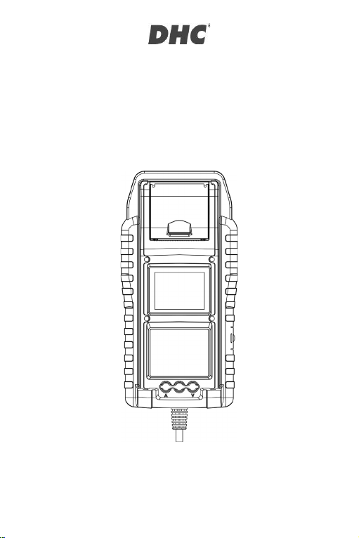
BT2410
Battery and Electrical
System Tester
Owner’s manual
Read entire manual before using this product.

2
MAIN FEATURES
1. 6V and 12V Starter Battery Test. (including Start-Stop Batteries)
2. 12V and 24V Cranking & Charging System Test.
3. USB Type-A connector for firmware update and accessories.
4. Print out test results.
IMPORTANT
Suggested operation range 0濎 (32ʲ) to 50濎 (122ʲ) in ambient temperature.
WARNING
WARNING: This product can expose you to chemicals including arsenic, which is
known to the State of California to cause cancer.
For more information, go to www.P65Warnings.ca.gov.
1. Working in the vicinity of a lead acid battery is dangerous. Batteries generate
explosive gases during normal battery operation. For this reason, it is of
utmost importance, if you have any doubt, that each time before using your
tester, you read these instructions very carefully.
2. To reduce risk of battery explosion, follow these instructions and those
published by the battery manufacturer and manufacturer of any equipment
you intend to use in the vicinity of the battery. Observe cautionary markings
on these items.
3. Do not expose the tester to rain or snow.
English

3
PERSONAL SAFETY PRECAUTIONS
1. Someone should be within range of your voice or close enough to come to
your aid when you work near a lead acid battery.
2. Have plenty of fresh water and soap nearby in case battery acid contacts skin,
clothing, or eyes.
3. Wear safety glasses and protective clothing.
4. If battery acid contacts skin or clothing, wash immediately with soap and
water. If acid enters eye, immediately flood eye with running cold water for at
least ten minutes and get medical attention immediately.
5. NEVER smoke or allow a spark or flame in vicinity of battery or engine.
6. Be extra cautious to reduce risk of dropping a metal tool onto the battery. It
could spark or short-circuit the battery or other electrical parts and could
cause an explosion.
7. Remove personal metal items such as rings, bracelets, necklaces, and
watches when working with a lead acid battery. It can produce a short circuit
current high enough to weld a ring or the like to metal causing a severe burn.
PREPARING TO TEST
1. Be sure area around battery is well ventilated while battery is being tested.
2. Clean battery terminals. Be careful to keep corrosion from contacting with
eyes.
3. Inspect the battery for cracked or broken case or cover. If battery is damaged,
do not use tester.
4. If the battery is not sealed maintenance free, add distilled water in each cell
until battery acid reaches level specified by the manufacturer. This helps
purge excessive gas from cells. Do not overfill.
5. If it is necessary to remove battery from vehicle to test, always remove ground
terminal from battery first. Make sure all accessories in the vehicle are off to
ensure you do not cause any arcing.
English
4
OPERATION AND USE
Each time you connect the tester to a battery, the tester will run a quick cable
verification to ensure a proper connection through the output cables to sensors in
the clamp jaws. If the connection checks out OK, the tester will proceed to the
Home Screen. If the connection is poor, the display will show “CHECK CABLE”.
In this case, check cable connections for visible signs of damage, as you may
need to re-connect the clamps to the battery or replace the cable end.
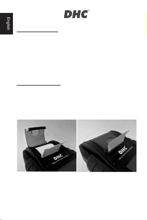
PAPER REPLACEMENT
1. Open the paper roll cover.
2. Place a new paper roll in the compartment. Make sure the thermal side is
upside placed as below.
3. Pull a short length of paper from the compartment and press down the cover
to close.
English

5
PRECAUTIONS FOR USING THE INTEGRATED PRINTER
To prevent overheating the integrated printer, it is not recommended to operate
the printer continuously without short breaks. The printer should be rested for at
least 1 minute for every 2 minutes of continuous use.
There is no need to be worried under normal operation, where one test only
requires one printout and continuous printing is highly unlikely. However, if the
integrated printer does start to get warm, please allow it to cool down by
temporarily halting any printing actions.
HOW TO REPLACE CLAMP SET
1. Detach the clamp set when in need of replacement.
2. Make sure the new clamp set is properly connected.
*Do not detach the cables unless necessary to ensure the pins are not exposed to
the moisture and acidic liquids which could cause rusting and corrosion.
INSTALL / REPLACE THE INTERNAL BATTERIES
The tester offers two different options for its internal batteries.
A. 6pcs AA batteries.
B. 2pcs 18650 rechargeable lithium batteries.
English
6
Important
It is recommended that the user to apply protected type 18650 lithium batteries
instead of unprotected type 18650 batteries.
Because the circuit of the protected type 18650 battery is embedded in the cell
packaging (battery casing) which protects the cell from “over charge”, heat or
“over discharge”, over current and short circuit and less likely to overheat, burst or
start on fire.
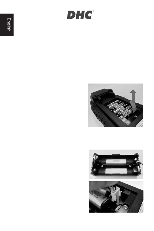
Replace / Install the AA batteries
1. Unscrew the battery cover to access
the battery compartment.
2. Pull the strap up to remove the AA
batteries and install new ones (Always
keep the strap under the batteries.)
3. Close the battery cover and tighten
the screw.
Replace / Install the rechargeable 18650 lithium batteries
1. Unscrew the battery cover to access
the battery compartment.
2. Install / Replace the 18650 lithium
batteries from the battery holder.
3. Plug in the connector of the 18650
lithium battery holder.
4. Place the 18650 lithium battery holder
in position. (Always keep the strap
under the battery holder.)
5. Close the battery cover and tighten the
screw. (Make sure the battery cover
English

7
doesn’t clip on the cables of the battery
holder when closing.)
6. Tighten the srew of the battery cover.
*18650 lithium batteries are not
included in the package.
6V, 12V, AND 24V BATTERY TEST
1. Select “Battery Test” from the
main menu.
2. Select “6V/12V/24V Battery Test”.
3. Select battery voltage.
4. Enter VIN via external barcode
scanner or manually.
z Scan:
Plug the external barcode
scanner into the USB port
on the tester. (only supports
USB HID-KBW interface)
Select the QR code icon to
enter scan mode. The
scanner will power on.
Scan the VIN code.
Select “NEXT” to proceed.
z Manual input:
Press ENTER when the input area is highlighted to initiate the virtual
keyboard.
Type in the VIN and select “ аġ” to close the virtual keyboard.
Select “NEXT” to proceed.
English

8
z Note:
Highlight the “X” icon and press ENTER to clear the input area.
Skip the process by directly selecting “NEXT”.
Invalid VIN warning will pop up if the VIN does not meet requirements in
terms of length or character. Select “Yes” to continue without modifying
the VIN. Select “No” to return and reenter the VIN.
5. Select “SETUP” to edit the battery testing criteria. (Testing criteria will be
stored after each test, select “START” to reuse previous settings.)
6. Select battery type. (available types: FLOODED, AGM FLAT, AGM SPIRAL,
VRLA/GEL, EFB.)
7. Select rating. (available ratings: CCA/SAE, DIN, EN, EN2, IEC, JIS, CA/MCA)
8. Select capacity. Available capacity range:
z 25 to 3000 CCA/SAE
z 25 to 2830 EN
z 25 to 2710 EN2
z 25 to 1985 IEC
z JIS (by battery type)
z 25 to 1685 DIN
z 25 to 3600 CA/MCA
9. Confirm battery position by
selecting the YES/NO option of
“TEST IN VEHICLE?”.
10. The tester will then check if the
user would like to proceed to an
In-Vehicle Test.
z If YES, the tester will
automatically proceed to the
system test after the battery
test is completed.
z If NO, the tester will perform only the battery test.
11. Temperature compensation. Select if battery temperature is above or below 0
濎/32ʲ.
12. Test result will be presented after test is completed, use directional keys to
review the test result. Select “PRINT” to print test result. Select “DONE” to
return to the main menu.
English

9
SURFACE CHARGE
If the tester detects a surface charge, a pop-up notification will ask the user to turn
on loads/headlights for 15 seconds to eliminate the surface charge.
Please note that vehicles with LED headlights and modern vehicle control
modules might not be able to eliminate surface charge within 15 seconds and the
pop-up may continue. Turn on more loads and repeat the process if this problem
persists.
BATTERY TEST RESULTS
z GOOD & PASS
The battery is good and capable of holding a charge.
z GOOD & RECHARGE
The battery is good but needs to be recharged.
z CAUTION
The battery may be serviced but performance will decline gradually. The
battery may fail under extreme weather conditions and should be closely
monitored, replacement might be necessary. Check battery connection and
charging system to ensure the battery is properly charged.
z RECHARGE & RETEST
Battery is discharged, the battery condition cannot be determined until it is
fully charged. Recharge and retest the battery.
z BAD & REPLACE
The battery will not hold a charge. It should be replaced immediately.
z BAD CELL & REPLACE
The battery has at least one cell short circuit. It should be replaced
immediately.
z LOAD ERROR
Failed to measure battery condition, please make sure the battery is not over
3000CCA/SAE, clamps are properly connected to the battery, and
clamps/cables are in a good state. Clamp/cable condition can be determined
English

10
with the “Cable Diagnosis” tool. If the problem persists or clamp/cable need
replacing, ask your dealer for replacement parts or further diagnostics.
12V AND 24V SYSTEM TEST
1. Select “SYSTEM TEST” from the main
menu.
2. Enter the VIN of the vehicle. (same
input method as 6V/12V/24V Battery
Test)
3. Turn off loads and start engine.
4. Use directional keys to review
cranking test result.
5. Select “NEXT” to proceed to charging
test.
6. “Is it a diesel engine?”
z If YES, the tester will ask the user
to rev the engine for 40 seconds
before proceeding to idle & load
on test.
z If NO, the tester will proceed with
the idle and load on test directly.
7. Select “NEXT” when idle test is
completed and move on to the ripple &
load on test.
8. Turn on loads and rev engine for 15
seconds.
(The tester will countdown 15
seconds)
9. Once completed, the ripple & load test results are displayed.
English

11
10. Select NEXT to review the complete
system test results including the
cranking, idle, ripple, and load on test
results.
11. Use directional keys to switch
between 4 different pages of the
system test results.
12. Select PRINT if you would like to print
out the system test result.
CRANKING TEST RESULTS
z CRANKING VOLTS NORMAL
The system is showing normal draw.
z CRANKING VOLTS LOW
The cranking voltage is below normal limits, troubleshoot the starter with
manufacturers recommended procedure.
z CRANKING VOLTS NOT DETECTED
The cranking voltage is not detected.
IDLE TEST RESULTS
z CHARGING SYSTEM NORMAL WHEN TESTING AT IDLE
The system is showing normal output from the alternator. No problem is
detected.
z HIGH CHARGING VOLTS WHEN TESTING AT IDLE
The voltage output from the alternator to the battery exceeds the normal limits
of a functioning regulator. Check to ensure there is no loose connection and
the ground connection is normal
If there is no connection issue, replace the regulator. Since most alternators
have the regulator built-in, this will require you to replace the alternator. The
normal high limit of a typical automotive regulator is 14.7 volts +/- 0.05. Check
English

12
manufacturer specifications for the correct limit, as it will vary by vehicle type
and manufacturer.
z LOW CHARGING VOLTS WHEN TESTING AT IDLE
The alternator is not providing sufficient current to the battery. Check the belts
to ensure the alternator is rotating with engine running.
If the belts are slipping or broken, replace the belts and retest. Check the
connections from the alternator to the battery. If the connection is loose or
heavily corroded, clean or replace the cable and retest. If the belts and
connections are in good condition, replace the alternator.
RIPPLE TEST RESULTS
z NORMAL RIPPLE DETECTED
Diodes function well in the alternator / starter.
z NO RIPPLE DETECTED
Ripple is not detected.
z EXCESS RIPPLE DETECTED
One or more diodes in the alternator are not functioning or there is stator
damage. Check to ensure the alternator mounting is sturdy and that the belts
are in good shape and functioning properly. If the mounting and belts are
good, replace the alternator.
LOAD ON TEST RESULTS
z CHARGING SYSTEM NORMAL WHEN LOAD ON TESTING
The system is showing normal output from the alternator. No problem
detected.
z CHARGING SYSTEM HIGH WHEN LOAD ON TESTING
The voltage output from the alternator to the battery exceeds the normal limits
of a functioning regulator.
Check to ensure there are no loose connections and that the ground
connection is normal. If there are no connection issues, replace the regulator.
English
13
Since most alternators have the regulator built-in, this will require you to
replace the alternator.
z CHARGING SYSTEM LOW WHEN LOAD ON TESTING
The alternator is not providing sufficient current for the system’s electrical
loads and the charging current for the battery. Check the belts to ensure the
alternator is rotating with the engine running. If the belts are slipping or broken,
replace the belts and retest.
Check the connections from the alternator to the battery. If the connection is
loose or heavily corroded, clean or replace the cable and retest. If the belts
and connections are in good working condition, replace the alternator.
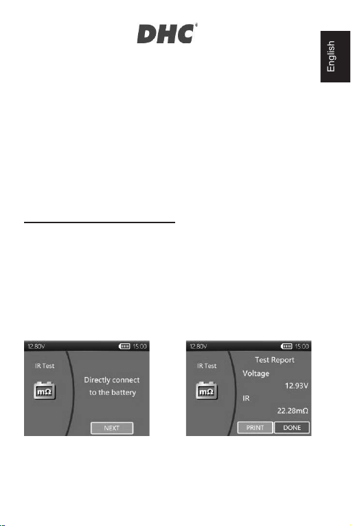
IR TEST (Internal Resistance Test)
1. Select IR TEST from the main menu.
2. Use the clamps to connect with the battery directly.
3. Measure the battery temperature by aiming the temperature sensor at the
battery.
4. Once the IR test is completed, the tester will display the voltage & internal
resistance value on the result page.
5. Select DONE to return to main menu or select PRINT to print out the IR test
result.
English

14
SETTINGS
Enter SETTING from the main menu and then select the item you would like to
adjust or proceed. Such as backlight, language, date & time, customized
information, and cable diagnosis. Or simply check the version of tester.
z BRIGHTNESS
1. Select “BRIGHTNESS” and use directional keys to adjust the brightness of
the display.
2. Press ENTER to confirm the setting and return to settings menu. Or press
BACK key to discard the change and return to the settings menu.
z LANGUAGE
1. Select “LANGUAGE” to choose the language wanted.
2. Press ENTER to confirm the setting and return to setting menu. Or press
BACK key to discard the change and return to the setting menu.
z DATE & TIME
Adjust date and time settings.
1. Use directional keys to adjust and press ENTER to proceed to the next item.
2. Once completed, press BACK to return to the setting menu.
z INFORMATION
1. Select “INFORMATION” to enable / disable, edit or erase the customized print
out info.
2. Press BACK to return to the setting menu.
z VERISON
1. Select “VERSION” to check the current firmware version and serial number of
the tester.
English

15
z CABLE DIAGNOSIS
1. Select “CABLE DIAGNOSIS” to perform self diagnosis of the cable set.
2. Follow on screen instructions.
1. Clamp on a battery that the voltage is above 12.4V. And make sure its
posts are clean.
2. Press ENTER to start.
3. Select START to start the cable diagnosis.
4. Result will be shown on the Test Report, use left and right key to switch
between positive/negative cable test result explanation.
HISTORY
z TEST RESULT
1. Select “HISTORY” and then enter “TEST RESULT” to review the test results
within the last 7 days.
2. Select between test types & days for reviewing.
3. Select “ERASE” will clear all the test records that saved in the tester.
z TEST COUNTER
1. If the “TEST COUNTER” is selected. The user may review the number of the
tests that have been performed. Or print out the counter if needed.
DHC PC SOFTWARE
NOTE:
DHC PC Software can be found and installed at the following sources:
1. On the disc included in the box. (selected models only)
2. At our website, www.dhc.com.tw.
Navigation instruction: DHC website ɦ Support ɦ Download
English

16
z CONNECTING THE TESTER TO YOUR PC
1. Launch DHC PC Software on your PC.
2. Connect the tester to PC with a USB cable.
z VIEW TEST RESULT
1. Click on the View Test Result icon.
2. Select the type of test result you would like to review.
3. Test results will then be presented with function buttons on the top left and
search box on the top right.
z DOWNLOAD TEST RESULT
1. Click on the Download Test Result icon.
2. Click START to initiate the download.
After the download is finished, a pop-up window will appear, click “Yes” if you
wish to clear all test result data on the tester, click “No” if otherwise.
z DELETE TEST RESULT
1. Click on the Delete Test Result icon.
2. Click “Yes” if you wish to clear all test result data on the tester.
3. Click “No” if you wish to keep all existing test result data on the tester.
z UPDATE FIRMWARE
1. Click on the Update Firmware icon.
2. Select the update file provided by DHC.
Warning:
Using firmware files from unknown sources may cause permanent
damage to the tester.
Do not decompress the file.
Do not disconnect the tester while update is in progress.
English

17
z TEST CODE
1. Click on the Test Code icon.
2. Click ADD to add a new field.
3. Enter the Test Code you would like to decode.
4. Results will be displayed after a valid code is entered.
GLOSSARY
What is a GEL battery?
A gel battery is a lead-acid electric storage battery that:
Ɏ is sealed using special pressure valves and should never be opened.
Ɏ is completely maintenance-free.
Ɏ uses thixotropic gelled electrolyte.
Ɏ uses a recombination reaction to prevent the escape of hydrogen and oxygen
gases normally lost in a flooded lead-acid battery (particularly in deep cycle
applications).
Ɏ is non-spillable, and therefore can be operated in virtually any position.
However, upside-down installation is not recommend-ed.
Ɏ Connections must be retorqued and the batteries should be cleaned
periodically.
What is an AGM battery?
An AGM battery is a lead-acid electric storage battery that:
Ɏ is sealed using special pressure valves and should never be opened.
Ɏ is completely maintenance-free.*
Ɏ has all of its electrolyte absorbed in separators consisting of a sponge-like
mass of matted glass fibers.
Ɏ uses a recombination reaction to prevent the escape of hydrogen and oxygen
gases normally lost in a flooded lead-acid battery (particularly in deep cycle
applications).
Ɏ is non-spillable, and therefore can be operated in virtually any position.
However, upside-down installation is not recommended.
English

18
Ɏ Connections must be retorqued and the batteries should be cleaned
periodically.
What is a VRLA battery?
Valve Regulated Lead Acid Battery – This type of battery is sealed Maintenance
Free with a bounce valve or valves in the top of them that opens when a preset
pressure is realized inside the battery and let’s the excess gas pressure out.
Then the valve resets itself.
What is a SLI battery?
These initials stand for Starting, Lighting and Ignition, which are the three basic
functions which a battery has to perform on all normal vehicles. Batteries given
this description will have been specifically designed for service on cars and trucks
within a voltage controlled electrical system. Those SLI batteries which are
intended for heavy haulage vehicles fitted with large diesel motors may often be
called COMMERCIAL batteries. They have to be much more powerful and more
robust than batteries intended for cars.
What is STATE OF HEALTH?
It means how much battery capacity is left (%) comparing with the marked original
battery capacity.
What is STATE OF CHARGE?
It means how many percent of the battery is actually charged.
What is CCA (COLD CRANKING AMPS)?
The current in amperes which a new fully charged battery can deliver for 30
seconds continuously without the terminal voltage falling below 1.2volts per cell,
after it has been cooled to 0OF and held at that temperature. This rating reflects
the ability of the battery to deliver engine starting currents under winter conditions.
English

19
What is AMPERE-HOUR?
The unit of measurement of electrical capacity. A current of one ampere for one
hour implies the delivery or receipt of one ampere-hour of electricity. Current
multiplied by time in hours equals ampere-hours.
TERMS AND CONDITIONS OF WARRANTY
Any battery tester defective in material or workmanship will be repaired or
replaced according to published defective return test repair procedures. The
existence of a defect shall be determined by the seller in accordance with
published procedures. The published test procedures are available upon request.
This warranty does not cover any unit that has been damaged due to accident,
abuse, alternation, use for a purpose other than that for which it was intended, or
failure to follow operating instructions. This warranty is expressly limited to
original retail buyers. This warranty is not assignable or transferable. Proof of
purchase is required for all alleged claims. Warranty cannot be authorized without
proof of purchase. Warranty claims must be sent pre-paid with dated proof of
purchase. Damage incurred during shipment is the responsibility of the shipper
(customer returning unit) If the returned unit qualifies for warranty, the shipper will
only incur shipping cost. The seller reserves the right to substitute or offer
alternative warranty options at its discretion.
The sole and exclusive remedy for any unit found to be defective is repair or
replacement, at the option of the seller. In no event shall the seller be liable for
any direct, indirect, special, incidental, or consequential damages (including lost
profit) whether based on warranty, contract, tort, or any other legal theory.
RETURN GOODS
Pack with sufficient over-pack to prevent damage during shipment. Damage
incurred during return shipment is not covered under this warranty. Repair costs
for such damages will be charged back to shipper.
REMARK
WHEN RETURNING GOODS, PLEASE SHOW “RETURN GOODS” ON ALL
INVOICES & RELATED SHIPPING DOCUMENTS TO PREVENT ANY EXTRA
CHARGE.”
English

20
BT2410
Testeur de Batterie et
Système Électrique
Manuel de l’utilisateur
Lisez entièrement ce manuel avant d'utiliser ce produit.
Française
This manual suits for next models
1
Table of contents
Languages:
Other DHC Test Equipment manuals


