Di-soric OGWTI-80G3-T4 User manual

OGWTI-80G3-T4
Rahmenlichtschranke
Frame light barrier
Détecteur photoélectrique à cadre
di-soric GmbH & Co. KG
Steinbeisstraße 6
DE-73660 Urbach
Germany
Tel: +49 (0) 7181/9879-0
[email protected] ∙ www.di-soric.com
213355
Stand 14.10.22, Änderungen vorbehalten
As of 10/14/22, subject to change
État 14.10.22, sous réserve de modifications
Funktion / Function / Fonction
IND. CONT. EQ.
29W7
Enclosure Type 1 Supply Class 2
NFPA 79 Applications only. For ad-
apters providing field wiring me-
ans refer to product information or
customer support.
. . .
1) Aktive Zone / Sensing zone / Zone active
2) Sender / Transmitter / Émetteur 3) Empfänger / Receiver / Récepteur mm
BK : schwarz / black / noir
BN : braun / brown / marron
BU : blau / blue / bleu
WH: weiß / white / blanc
Technische Daten Technical data Caractéristiques techniques +20°C, 24 V DC
Auswertung Evaluation Évaluation
Schaltend, Dynamisch/statisch umschaltbar / Swit-
ching, Dynamic/static switchable / De commutation, À
commutation dynamique/statique
Lichtfarbe Light color Couleur de lumière Infrarot / Infrared / Infrarouge
Auflösung Resolution Résolution 1,5mm / 2mm
Betriebsspannung Service voltage Tension de service 18 … 30V DC
Schaltausgang Switching output Sortie de commutation Gegentakt, 100mA, NO/NC / Push-pull, 100mA, NO/
NC / Push-pull, 100mA, NO/NC
Schnittstelle Interface Interface IO-Link V1.1.3, COM2
Umgebungstemperatur Betrieb Ambient temperature during operation Température ambiante de fonctionne-
ment -10 … +60°C
Schutzart Protection type Indice de protection IP 67
Sicherheitshinweise Safety instructions Consignes de sécurité
Allgemeiner Sicherheitshinweis
WARNUNG! Kein Sicherheitsbauteil gemäß 2006/42/
EG und EN 61496-1 /-2! Darf nicht zum Personen-
schutz eingesetzt werden! Nichtbeachtung kann zu
Tod oder schwersten Verletzungen führen! Nur bestim-
mungsgemäß verwenden!
General safety notice
WARNING! Not a safety component pursuant to
2006/42/EG and EN 61496-1/-2! May not be used for
personal protection! Non-compliance can lead to death
or serious injuries! Only use as directed!
Consigne de sécurité générale
AVERTISSEMENT! Ce produit n’est pas un composant
de sécurité au sens des règlementations 2006/42/CE
et NFEN61496-1/-2! Ne pas l’utiliser pour la protec-
tion des personnes! Le non-respect de cette consigne
peut entraîner la mort ou des blessures graves! N’utili-
ser le produit que selon son utilisation conforme!

OGWTI-80G3-T4
框式光电开关
di-soric GmbH & Co. KG
Steinbeisstraße 6
DE-73660 Urbach
Germany
Tel: +49 (0) 7181/9879-0
[email protected] ∙ www.di-soric.com
213355
版本 22.10.14,保留变更权
功能
IND. CONT. EQ.
29W7
Enclosure Type 1 Supply Class 2
NFPA 79 Applications only. For ad-
apters providing field wiring me-
ans refer to product information or
customer support.
. . .
1) 作用区
2) 发射器 3) 接收器 mm
BK : 黑色
BN : 棕色
BU : 蓝色
WH: 白色
技术数据 +20°C, 24 V DC
评估 开关版, 动态/静态可切换
光色 红外
分辨率 1,5mm / 2mm
工作电压 18 … 30V DC
开关输出端 推挽式, 100mA, NO/NC
接口 IO-Link V1.1.3, COM2
工作环境温度 -10 … +60°C
防护等级 IP 67
安全提示
一般安全提示
警告!没有符合 2006/42/EU 和 EN 61496-1 /-2 标准
的安全结构件!不得用于人身安全保护!不遵守规定
会导致死亡或重伤危险!仅按规定使用!

Allgemeine Hinweise General notes Remarques générales
Bestimmungsgemäße Verwendung: Intended use: Usage prévu:
Rahmenlichtschranken sind Sensoren mit integriertem
Sender und Empfänger. Die Sensoren werden zum be-
rührungslosen Erfassen von Objekten eingesetzt.
Frame light barriers are sensors with an integrated
transmitter and receiver. These sensors are used for the
contact-free detection of objects.
Les barrières lumineuses à cadre sont des capteurs avec
un émetteur et un récepteur intégrés. Les capteurs sont
utilisés pour la détection d’objets sans contact.
Montage: Assembly: Montage :
- Die Rahmenlichtschranke ist so anzubringen, dass das zu
erfassende Objekt den Erfassungsbereich frei passieren
kann.
- Die gerätespezifischen Angaben zu Anschluss und Betrieb
sind zu beachten.
- Befestigen Sie den Sensor an den Befestigungsbohrungen,
maximales Drehmoment von M4 Befestigungsschrauben:
1,4 Nm.
- Der Sensor kann in einer beliebigen Einbaulage montiert
werden, wobei auf eine erschütterungsfreie und schwin-
gungsdämpfende Montage zu achten ist.
- Der Sensor ist gegen mechanische Belastungen
z.B. Stöße und Schläge zu schützen.
- The frame light barrier should be installed so that the
object to be detected can freely pass through the
detection range.
- Device-specific information on connection and operation
must be observed.
- Mount the sensor at the mounting holes, maximum torque
of M4 mounting screws: 1.4 Nm.
- The sensor may be mounted in any installation position,
as long as mounting is performed free of vibration.
- The sensor must be protected from mechanical loads such
as shocks and impacts.
- La barrière lumineuse à cadre doit être montée de façon à
ce que l’objet à détecter puisse passer librement dans la
zone de détection.
- Les données relatives au raccordement et au fonctionne-
ment de l’appareil doivent être prises en compte.
- Fixez le capteur sur les trous de fixation. Couple maximal
des vis de fixation M4: 1,4Nm.
- Le capteur peut être monté dans n’importe quelle position,
à condition d’assurer l’absence de secousses et de
vibrations.
- Le capteur doit être protégé contre les sollicitations
mécaniques, par ex. les coups et chocs.
Fremdlicht: Ambient light: Lumière ambiante :
Werden mehrere Rahmenlichtschranken in räumlicher Nähe
eingesetzt, kann es zur gegenseitigen Beeinflussung kom-
men.
Stellen Sie sicher, dass der Sender (Steckerseite) der Rah-
menlichtschranke nicht in den Empfänger (Seite von Taste -)
einer benachbarten Rahmenlichtschranke strahlt.
Möglichkeiten der Montage:
- Benachbarte Rahmenlichtschranken um 180° versetzt
anordnen
- Benachbarte Rahmenlichtschranken mechanisch
abschatten
If several frame light barriers are used in close proximity, this
can lead to mutual influencing.
Make sure that the frame light barrier transmitter (connector
side) does not radiate into the receiver (side of -button) of a
neighboring frame light barrier.
Assembly options:
- Arrange neighboring frame light barriers oset by 180°
- Mechanically shadow neighboring frame light barriers
Si plusieurs barrières lumineuses à cadre sont montées à
proximité les unes des autres, elles peuvent s’influencer
mutuellement.
Assurez-vous que l’émetteur (côté connecteur) de la barrière
lumineuse à cadre n’émette pas vers le récepteur (côté
touche -) d’une barrière lumineuse à cadre voisine.
Montages possibles:
- Disposer les barrières lumineuses à cadre voisines
en les tournant de 180°
- Occulter mécaniquement les barrières lumineuses
à cadre voisines
Erfassungsbereich: Detection range: Zone de détection:
Zu erkennende Objekte müssen sich innerhalb des
Erfassungsbereiches befinden.
An den Randbereichen des Erfassungsbereiches kann die
Auflösung etwas herabgesetzt sein.
The objects to be detected must be located within the
detection range.
The resolution can be reduced slightly on the edge regions
of the detection range.
Les objets à détecter doivent se trouver dans
la zone de détection.
La résolution peut être légèrement réduite sur les bords
de la zone de détection.
T (max.)
T (min.)
Temperaturbereich: Temperature range: Plage de température:
Der Betrieb außerhalb des angegebenen Temperaturbe-
reiches ist nicht zulässig.
Operation outside of the specified temperature range is not
allowed.
Le fonctionnement en dehors de la plage de température
indiquée n’est pas autorisé.
Frontscheibe: Front panel: Face avant :
Es ist zu beachten, dass sich kein Schmutz auf den Front-
scheiben befindet. Die Frontscheibe ist mit einem weichen
staubfreien Tuch zu reinigen.
There may be no dirt on the front panels. The front panel
should be cleaned with a soft, dust-free cloth.
Il faut s’assurer que la face avant est exempte de saleté.
Il convient de nettoyer la face avant à l’aide d’un chion doux
et exempt de poussière.
3
Anzeigeelemente Display element Éléments d’achage
LED-Anzeige LED display Achage LED
LED1 (On) grün Sensor betriebsbereit
blinkt grün IO-Link Kommunikation aktiv
LED2 (D/(S)) weiss Sensormode Dynamisch aktiv
LED3 (Q1) gelb Schaltausgang 1 (Pin4) aktiv
LED4 (Q2/E) gelb Schaltausgang 2 (Pin2) aktiv
rot Anzeige von geringer Funktionsreserve
LED1 (On) green Sensor ready
flashes green IO-Link communication active
LED2 (D/(S)) white Dynamic sensor mode active
LED3 (Q1) yellow Switching output 1 (Pin 4) active
LED4 (Q2/E) yellow Switching output 2 (Pin 2) active
red Display of low functional reserve
LED1 (On) vert Capteur prêt à l’emploi
clignote
en vert Communication IO-Link active
LED2 (D/(S)) blanc Le mode de détection dynamique est actif
LED3 (Q1) jaune Sortie de commutation1 (broche4) active
LED4 (Q2/E) jaune Sortie de commutation2 (broche2) active
rouge Indication de faible réserve de fonctionnement
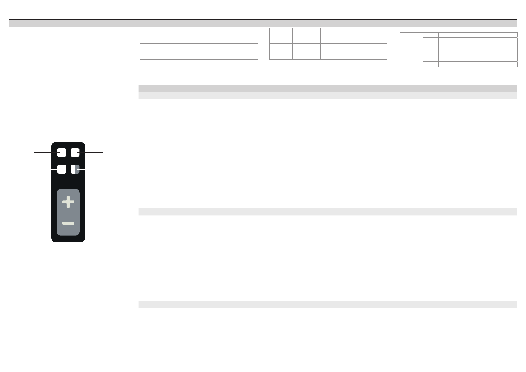
Tastatur Bedienung Keypad operation Commande au moyen du clavier
TEACH
On D/(S)
Q1 Q2/E
LED1 LED2
LED3 LED4
Empfindlichkeitseinstellung Sensitivity adjustment Réglage de la sensibilité
Auto Teach Auto-teach Apprentissage automatique
Mit Auto-Teach lassen sich fallende Objekte einlernen,
größere Objekte werden erkannt
Taste +für Teach-Vorgang 2-4 Sek. drücken. Der Teach
Vorgang startet. Möglichst viele Objekte an unterschied-
lichen Positionen durch den Erfassungsbereich des Sensors
fallen lassen.
Ein weiteres Betätigen der Taste +beendet den Teach-
Vorgang. Alternativ beendet der Sensor den Vorgang nach
60 Sek. automatisch.
Falling objects can be taught using auto-teach, larger objects
are detected
Press the +button for 2-4 sec. for the teach process. The
teach process starts. Allow as many objects as possible
to fall through the detection range of the sensor at dierent
positions.
Pressing the +button again will end the teach process.
Alternatively, the sensor will end the process automatically
after 60 sec.
L’apprentissage automatique permet la programmation
d’objets en chute; les plus grands objets sont détectés
Appuyer sur la touche +pendant 2 à 4secondes pour
l’apprentissage. L’apprentissage démarre. Faire tomber le
plus grand nombre possible d’objets à des positions dié-
rentes à travers la zone de détection du capteur.
Actionner à nouveau la touche +permet d’arrêter
l’apprentissage. Par défaut, le capteur arrête automatique-
ment le processus après 60secondes.
LED Anzeigen:
Rasches Blinken LED3 (gelb): Teach Vorgang ist gestartet
2-maliges Aufleuchten LED3 (gelb): Schaltpunkt ermittelt,
Teach Vorgang erfolgreich beendet
4-maliges Aufleuchten LED3 (gelb): kein geeigneter
Schaltpunkt ermittelt, Teach Vorgang beendet
Hinweis: Wurde während des Teach-Vorganges kein Objekt
durch den Sensor geführt, wird der Schaltpunkt auf die
höchste Empfindlichkeit gestellt. Die LED3 (gelb) leuchtet
4 mal auf.
LED displays:
Rapid blinking LED3 (yellow): Teach process has started
Flashes 2x LED3 (yellow): Switching point determined, teach
process ended successfully
Flashes 4x LED3 (yellow): No suitable switching point deter-
mined, teach process ended
Note: If no object was run through the sensor during the
teach process, then the switching point will be set to the
highest sensitivity. LED3 (yellow) flashes 4 times.
LED d’indication:
La LED3 clignote rapidement (jaune): l’apprentissage a
démarré
La LED3 s’allume 2fois (jaune): point de commutation
déterminé, apprentissage terminé avec succès
La LED3 s’allume 4fois (jaune): aucun point de commutati-
on adapté n’est déterminé, apprentissage terminé
Remarque: si aucun objet ne passe par le capteur pendant
l’apprentissage, le point de commutation est réglé sur la
sensibilité la plus élevée. La LED3 (jaune) s’allume 4fois.
Manuelle Anpassung der Empfindlichkeit Manual adjustment of sensitivity Réglage manuel de la sensibilité
Durch kurzes Drücken von +und -lässt sich der
Schaltpunkt von Schaltausgang 1 in kleinen Schritten
anpassen. Jeder Tastendruck erhöht bzw. verringert den
Schaltpunkt um 10.
Erhöhung der Empfindlichkeit, zur Erkennung kleinerer Ob-
jekte: kurzes Drücken von -, der Sensor wird empfindlicher.
Reduktion der Empfindlichkeit, zur Erhöhung der
Funktionsreserve: kurzes Drücken von +, der Sensor wird
unempfindlicher.
Briefly pressing the +and -buttons will adjust the switching
point of switching output 1 in small increments. Each press
of the button will increase/decrease the switching point by
10.
Increasing the sensitivity for detecting smaller objects:
Briefly press -to increase sensor sensitivity.
Reducing the sensitivity to increase the functional reserve:
Briefly press +to decrease sensor sensitivity.
De courtes pressions sur +et -permettent d’ajuster le point
de commutation de la sortie de commutation 1 par petits
pas. Chaque actionnement de touche augmente ou diminue
le point de commutation de 10.
Augmentation de la sensibilité, pour la détection de plus pe-
tits objets: appuyer brièvement sur -augmente la sensibilité
du capteur.
Réduction de la sensibilité, pour l’augmentation de la réserve
de fonctionnement: appuyer brièvement sur +diminue la
sensibilité du capteur.
LED Anzeigen:
1-maliges Aufleuchten LED3 (gelb):
Schaltpunkt wurde verschoben
4-maliges Aufleuchten LED3 (gelb):
Schaltpunktgrenze wurde erreicht
LED displays:
Flashes 1x LED3 (yellow):
Switching point has been shifted
Flashes 4x LED3 (yellow):
Switching point has been reached
LED d’indication:
La LED3 s’allume 1fois (jaune):
Le point de commutation est déplacé
La LED3 s’allume 4fois (jaune):
La limite du point de commutation est atteinte
Sensormode statisch/dynamisch umschalten Changing the sensor mode to static/dynamic Commuter le mode de détection statique/dynamique
Taste + für 4-6 Sek. drücken, der Sensormode wird
zwischen statisch und dynamisch umgeschaltet
Pressing the + button for 4-6 sec. will switch the sensor
mode between static and dynamic
Appuyer sur la touche + pendant 4 à 6secondes, pour
commuter le mode de détection statique/dynamique
LED Anzeige:
LED2 (weiß) an: Sensormode Dynamisch aktiv
LED display:
LED2 (white) on: Dynamic sensor mode active
LED d’indication:
La LED2 (blanche) est allumée: le mode de détection
dynamique est actif
4

NO/NC umschalten Changing to NO/NC Basculer entre NO et NC
Taste +für >6 Sek. drücken, der Schaltausgang wird zwi-
schen NO/NC umgeschaltet
Pressing the +button for >6 sec. will switch the switching
output between NO/NC
Appuyer sur la touche +pendant plus de 6secondes,
pour basculer la sortie de commutation entre NO/NC
Referenzwert setzen Setting a reference value Configurer la valeur de référence
Mit dieser Funktion wird der Sensor in der individuellen
Einbausituation auf den Messwert 0 abgeglichen.
Mit dem Abgleich lassen sich kleine Objekte bei individuellen
Einbausituationen besser erkennen.
Während des Abgleiches ist zu beachten, dass sich kein
Schmutz auf der Frontscheibe befindet.
Zum Zeitpunkt des Abgleiches dürfen sich keine Objekte im
Erfassungsbereich befinden.
Taste -für >6 Sek. drücken, der Abgleichvorgang startet
und wird automatisch beendet.
Using this function, the sensor is calibrated to the measure-
ment value 0 in the individual installation situation.
This calibration enables small objects to be better detected
for individual installation situations.
There must be no dirt on the front panel during the
calibration.
No objects may be in the detection range during the
calibration.
Press the -button for > 6 sec., the calibration will start and
end automatically.
Cette fonction permet d’ajuster le capteur à la valeur
mesurée 0 dans la situation de montage individuelle.
L’ajustement permet de mieux détecter les petits objets
dans les situations de montage individuelles.
Pendant l’ajustement, il faut s’assurer que la face avant
est exempte de saleté.
Au moment de l’ajustement, aucun objet ne doit se trouver
dans la zone de détection.
Appuyer sur la touche -pendant plus de 6secondes,
l’ajustement démarre et s’arrête automatiquement.
LED Anzeigen:
2-maliges Aufleuchten LED3 (gelb):
Abgleichvorgang erfolgreich beendet
4-maliges Aufleuchten LED3 (gelb), LED4 (rot) an:
Abgleichvorgang grenzwertig beendet
LED4 (rot) dauerhaft an: Abgleichvorgang nicht erfolgreich
LED displays:
Flashes 2x LED3 (yellow):
Calibration process ended successfully
Flashes 4x LED3 (yellow), LED4 (red) on:
Calibration criteria ended with marginal success
LED4 (red) permanently on: Calibration process unsuccessful
LED d’indication:
La LED3 s’allume 2fois (jaune):
ajustement terminé avec succès
La LED3 s’allume 4fois (jaune), la LED4 (rouge) s’allume:
ajustement terminé en atteignant une limite
La LED4 (rouge) est allumée en continu:
échec de l’ajustement
Werkseinstellung zurücksetzen Resetting to the factory setting Réinitialiser les réglages d’usine
Versorgungsspannung trennen, Versorgungsspannung
anlegen und gleichzeitig +Taste für > 2 Sek. drücken
Disconnect from the power supply, reconnect to the power
supply and simultaneously press the +button for > 2 sec
Couper la tension d’alimentation, appliquer la tension
d’alimentation et appuyer sur la touche +pendant plus de
2secondes
LED Anzeige:
2-maliges Aufleuchten LED3 (gelb):
Werkseinstellung erfolgreich zurückgesetzt
LED display:
Flashes 2x LED3 (yellow):
Successful reset to the factory setting
LED d’indication:
La LED3 s’allume 2fois (jaune):
Réglages d’usine réinitialisés avec succès
5
Table of contents
Other Di-soric Industrial Equipment manuals


