The refrigerated equipment should never be installed:
a -near sources of heat such as radiators. direct or indirect sunlight or other equip-
ment which produces heat (photo F);
b -in line with draughts coming from doors. windows or ajr conditioning systems
(photo F).
Do not close or obstruct the ventilation openings of the refrigeration unit. because
this would stop the airflow which cools the refrigeration unit causing a bad working.
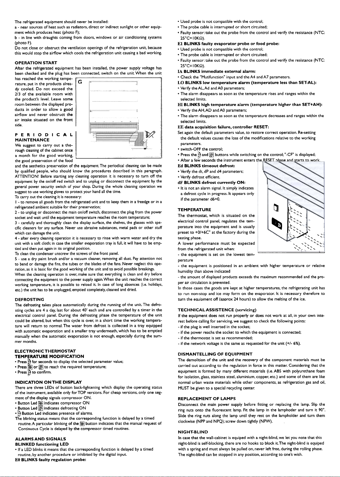
OPERATION START
After the refrigerated equipment has been installed, the power supply voltage has
been checked and the plug has been connected, switch on the unit. When the unit
has reached the working tempe-
rature, put in the products alrea-
dy cooled. Do not exceed the
2/3 of the available room with
the product's level. Leave some
room between the displayed pro-
ducts in order to allow a good
airflow and never obstruct the
air intake situated on the front
side.
G
~
PERIODICAL IMAINTENANCEWe suggest to carry out a tho-
rough cleaning of the cabinet once
a month for the good working,
the good preservation of the food
and the aesthetics preservation of the equipment. The periodical cleaning can be made
by qualified people, who should know the procedures described in this paragraph.
ATTENTION! Before starting any cleaning operation it is necessary to turn off the
equipment by the on/off red switch and to unplug or disconnect the equipment by the
generai power security switch of your shop. During the whole cleaning operation we
suggest to use working gloves to protect your hand alI the time.
To carry out the cleaning it is necessary:
I -to remove ali goods from the refrigerated unit and to keep them in a freedge or in a
refrigerated ambient suitable for their preservation;
2 -to unplug or disconnect the main on/off switch, disconnect the plug from the power
socket and wait until the equipment temperature reaches the room temperature;
3 -carefully and thoroughly clean the display surface, the shelves, the glasses with spe-
cific cleaners for any surface. Never use abrasive substances, metal pads or other stuff
which can damage the unit.
4 -after every cleaning operation it is necessary to rinse with warm water and dry the
unit with a soft cloth; in case the smaller evaporation tray is full, it will have to be emp-
tied and then put again in its originai position.
To clean the condenser unscrew the screws of the front panel.
5 -use a dry paint brush and/or a vacuum cleaner, removing ali dust. Pay attention not
to bend or damage the fins, the tubes or the blades of the fans. Never neglect this ope-
ration, as it is basic for the good working of the unit and to avoid possible breakings.
When the cleaning operation is over, make sure that everything is clean and dry before
connecting the equipment to the power supply again.When the unit reaches the correct
working temperature, it is possible to reload it. In case of long absences (i.e. holidays,
etc.) the unit has to be unplugged, emptied completely, cleaned and dried.
.Used probe is not compatible with the control;
.The probe cable is interrupted or short circuited;
.Faulty sensor; take out the probe from the control and verify the resistance (NTC;
25°C= IOKQ).
El BLINKS faulty evaporator probe or food probe:
.Used probe is not compatible with the control;
.The probe cable is interrupted or short circuited;
.Faulty sensor. take out the probe from the control and verify the resistance (NTC:
25°C= IOKQ).
IA BLINKS immediate external alarm:
.Check the "Mutifunction" input and the A4 and A7 parameters.
LO BLINKS low temperature alarm (temperature less than SET-AL):
.Verify the AL.Ad and AO parameters;
.The alarm disappears as soon as the temperature rises and ranges within the
selected limits.
HI BLINKS high temperature alarm (temperature higher than SET+AH):
.Verify the AH.AD and AO parameters;
.The alarm disappears as soon as the temperature decreases and ranges within the
selected limits.
EE data acquisition failure. controller RESET:
Set again the default parameters value. to restore correct operation. Re-setting
the default values causes the loss of the modifìcations relative to the working
parameters.
.switch-OFF the control;
.Press the ~ and ~ buttons while switching on the control; "-CF" is displayed;
.After a few seconds the instrument enters the RESET ')hase and starts to work.
Ed BLINKS timeout defrost:
.Verify the dt. dP and d4 parameters;
.Verify defrost efficient.
dF BLINKS defrost currently ON:
.It is not an alarm signal. It simply indicates
a defrost cycle in progress.lt appears only
if the parameter d6=O.
~
,
,
x '' "
(:, '~',
'",
, "
"':::,
, ,
,
, ,
, ,
TEMPERATURE
The thermostat. which is situated on the
electrical control panel. regulates the tem-
perature into the equipment and is usually
preset to +O/+6Co at the factory during the
testing phase.
A lower performance must be expected
from the refrigerated unit when:
-the equipment is set on the lowest tem- ' -,
perature
-the equipment is positioned in an ambient with higher temperature or relative
humidity than above indicated
-the amount of displayed products exceeds the maximum recommended and the pro-
per air circulation is prevented.
In those cases the goods are kept at higher temperatures. the refrigerating unit has
to run non-stop and ice may form on the evaporator. It is necessary therefore to
turn the equipment off (approx 24 hours) to allow the melting of the ice.
DEFROSTING
The defrosting takes piace automatically during the running of the unit. The defro-
sting cycles are 4 a day, last for about 40' each and are controlled by a timer in the
electrical control panel. During the defrosting phase the temperature of the unit
could be altered, but when this cycle is over, in a short time the working tempera-
ture will return to normal. The water from defrost is collected in a tray equipped
with automatic evaporation and a smaller tray underneath, which has to be emptied
manually when the automatic evaporation is not enough, especially during the sum-
mer months.
TECHNICAL ASSISTENCE (servicing)
If the equipment does not run properly or does not work at ali, in your own inte.
rest before calling for servicing, we suggest to check the following points:
-if the plug is well inserted in the socket;
-if the power reachs the socket to which the equipment is connected;
-if the thermostat is set as recommended;
-if the network voltage is the same as requested for the unit (+1- 6%).
DISMANTELLING OF EQUIPMENT
The demolition of the unit and the recovery of the component materials must be
carried out according to the regulation in force in this matter. Considering that the
equipment is formed by many different materials (i.e. ABS with polyurethane foam
for isolation. glass. stainless steel. aluminium. copper. etc.) and some of them are like
normal urban waste materials while other components. as refrigeration gas and oil.
MUST be given to a special recycling center.
REPLACEMENT OF LAMPS
Disconnect the main power supply before fitting or replacing the lamp. Slip the
ring nuts onto the fluorescent lamp. Fit the lamp in the lamphoder and turn it 90°.
Slide the ring nuts along the lamp until they rest on the lampholder and turn them
clockwise (NPP and NPQ); screw down tightly (NPW).
NIGHT-BLIND
In case that the wall-cabinet is equiped with a night-blind. we let you note that this
night-blind is self-blocking. there are no hooks to block it.The night-blind is equiped
with a spring and must always be pulled on. never left free. during the rolling phase.
The night-blind can be stopped in any position. according to one.s wish.
ELECTRONIC THERMOSTAT
TEMPERATURE MODIFICATION
.Press ~for seconds to display the selected parameter value;
.Press '* or ~ to reach the required temperature;
.Press to confìrm.
INDICATION ONTHE DISPLAY
There are three LEDs of button back-Iightening which display the operating status
of the instrument. available only for TOP versions. For cheap versions. only one seg-
ment of the display signals compressor ON.
.Button Led ~ indicates compressor ON
.Button Led ~ indicates defrosting ON
.~ Button Led indicates presence of alarms.
T~e blinking status means that the corresponding function is delayed by a timed
routine.A particular blinking of the ~ button indicates that the manual request of
Continuous Cycle is delayed by the compressor timed routines.
ALARMSAND SIGNALS
BLINKED functioning LED
.If a LED blinks it means that the corresponding function is delayed by a timed
routine. by another procedure or inhibited by the digital input.
EO BLINKS faulty regulation probe:
-[ '}. ,,."
\ "
~ \;::;~
"
\ ' ,
.' ,