Dictator DICTAMAT Move Installation and operating instructions


Imprint
Dictator Technik GmbH
Gutenbergstraße 9
86356 Neusäß
Germany
Telephone: +49 821 24673 0
Fax: +49 821 24673 90
E-mail: [email protected]
Internet: www.dictator.de

Contents
Translated User Manual MultiMove drive system MultiControl control system Version 2020-07 page 3 ׀35
1How to Read this User Manual ......................................................................5
1.1 Target group.....................................................................................................5
1.2 Conventions......................................................................................................5
1.2.1 Symbols and signal words................................................................................5
1.2.2 Format ..............................................................................................................6
1.2.3 Terms and abbreviations ..................................................................................6
1.3 Contents and structure of the manual...............................................................8
1.3.1 Integral parts of the user manual......................................................................8
1.3.2 Referenced documents.....................................................................................8
2The Operating System....................................................................................9
2.1 Components included.......................................................................................9
2.2 Main components ...........................................................................................10
2.3 Mode of operation and functioning..................................................................11
2.4 Safety systems ...............................................................................................11
2.5 Explanation of the device’s marking ...............................................................11
3Safety.............................................................................................................13
3.1 How to act in case of an emergency...............................................................13
3.2 Intended use...................................................................................................14
3.3 Foreseeable use.............................................................................................14
3.4 Responsibilities of the machine builder...........................................................15
3.4.1 Technical demands.........................................................................................15
3.4.2 Demands on the user information for the operator of the machine.................16
3.5 Demands on the qualification of the personnel...............................................17
3.5.1 Who may what?..............................................................................................17
3.5.2 Definitions of the required skills......................................................................17
3.6 Personal protective equipment .......................................................................18
3.7 Conditions of the surroundings.......................................................................18
4Technical Data ..............................................................................................19
4.1 Dimensions and weights.................................................................................19
4.2 Electrical system.............................................................................................19
5In-House Transport, Unpacking ..................................................................20
5.1 Safety .............................................................................................................20
5.2 Transporting and unpacking the drive system ................................................20
6Mounting, Installation...................................................................................21
6.1 Dimensions and fixing.....................................................................................21
6.2 Safety .............................................................................................................22

Contents
Translated User Manual MultiMove drive system MultiControl control system Version 2020-07 page 4 ׀35
6.3 Mounting of the operating system...................................................................24
7Troubleshooting ...........................................................................................29
8Maintenance..................................................................................................30
8.1 Safety .............................................................................................................30
8.2 Inspection and maintenance plan ...................................................................32
8.2.1 Checking of cables, wires and connections....................................................33
8.3 Wear parts, spares .........................................................................................34
8.3.1 Safety-related wear parts, spares...................................................................34
8.3.2 Other wear parts, spares ................................................................................34
9Proper Disposal ............................................................................................35
9.1 Safety .............................................................................................................35
9.2 Proper disposal...............................................................................................35
How to Read this User Manual
Translated User Manual MultiMove drive system MultiControl control system Version 2020-07 page 5 ׀35
1How to Read this User Manual
1.1 Target group
This user manual contains all information necessary for the personnel of the
engine builder to be able to transport, mount and install the product according
to regulations.
Furthermore, this user manual contains information for the operator of the
machine into which this product is integrated.
For the requirements regarding the qualification of the personnel, see 3.5
Responsibilities of the machine builder.
1.2 Conventions
1.2.1 Symbols and signal words
Label
Meaning
Calls your attention to the handling and effects of safety
information.
WARNING
Indicates a dangerous situation that can result in severe
injury or death if not avoided.
ATTENTION
Indicates a dangerous situation which can result in a slight
to medium severe injury if not avoided.
NOTE:
Points to possible material damage and other important
information in connection with the operating system.

How to Read this User Manual
Translated User Manual MultiMove drive system MultiControl control system Version 2020-07 page 6 of 35
1.2.2 Format
Operation modes, operating elements, control inputs and cross references
are written in italics.
Control signals and parameters are written in Courier fonts.
<KEYS> on operating elements or the keypad of the display which have to
be pressed for input, are written in capital letters and put in squared
brackets.
1.2.3 Terms and abbreviations
Term / Abbreviation
Explanation
Driving medium
Toothed belt/chain/toothed rack
Dead-man operation
(control system without
latch)
The sliding element moves only when a key
(OPEN/CLOSE) is being pressed. As soon as the key is
released, the movement will stop according to EN 12453.
Operating system
Operator including the control system and driving medium
for the horizontal movement of sliding elements
Sliding elements
All horizontally moved masses such as e.g. doors,
windows, blinds, etc.
Impulse operation
A single and short pressing of the key will start the
movement of the sliding element.
Emergency service
The emergency service can be activated to keep the
sliding element in operative condition when the safety
devices have broken down. The sliding element moves
only when a key (OPEN/CLOSE) is being pressed. As
soon as the key is released, the movement will stop
according to EN 12453. All safety devices are ignored.
Teach-in run
Determining of the final positions. Only necessary for initial
operation.
Dynamic run
Learning of the forces, acceleration values and speeds.
Necessary for initial operation and after modifications of
the installation.
Reference run
Seeking the physical limit stop CLOSE as a reference for
positions and distances. Necessary after a power cut.
Emergency-STOP
Stopping and reversing the sliding element when the
safety devices recognize an obstacle or when the input
"EMERGENCY-STOP" is being activated.

How to Read this User Manual
Translated User Manual MultiMove drive system MultiControl control system Version 2020-07 page 7 ׀35
Term / Abbreviation
Explanation
Software-Emergency-
STOP
Stopping and reversing the sliding element when an
obstacle is detected by touching the sliding element (the
retardation or acceleration of the sliding element when
hitting the obstacle will exceeded or fall below the speed
learned during the dynamic run and the sliding element is
stopped and reversed).

How to Read this User Manual
Translated User Manual MultiMove drive system MultiControl control system Version 2020-07 page 8 of 35
1.3 Contents and structure of the manual
1.3.1 Integral parts of the user manual
This user manual consists of the following A4 lever arch files (loose-leaf):
Part
Contents
1
Brief instruction
2
Safety notices
3
General part
4
Customer-specific part (mounting, control system
and data of the installation)
1.3.2 Referenced documents
Data provided by the customer (questionnaire, drawings, functional description,
etc…), declarations of incorporation

The Operating System
Translated User Manual MultiMove drive system MultiControl control system Version 2020-07 page 9 ׀35
2The Operating System
2.1 Components included
NOTE:
Connection cables for the power supply of the control system and a main switch
possibly having to be installed, operating and safety elements form not part of
the standard components.
Operator with cable set to the control system
Standard mounting brackets
Idler pulley
Belt fixing device(s)
Driving medium (toothed belt, chain)
User manual
The Operating System
Translated User Manual MultiMove drive system MultiControl control system Version 2020-07 page 10 of 35
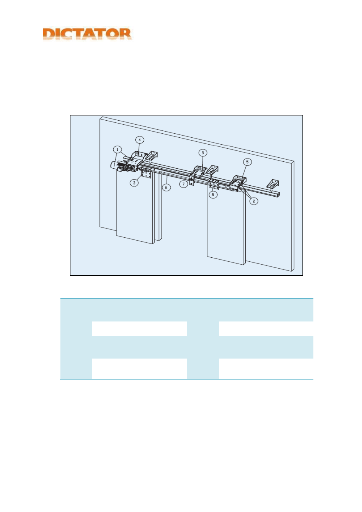
2.2 Main components
1
Door operator with
U-bracket
5
Wall bracket for idler pulley
(optional)
2
Idler pulley with U-bracket
6
Toothed belt
3
Belt fixing device
7
Supporting roller with
U- bracket (optional)
4
Wall bracket for door
operator (optional)
8
Belt fixing device for 2nd
door leaf (optional)

The Operating System
Translated User Manual MultiMove drive system MultiControl control system Version 2020-07 page 11 ׀35
2.3 Mode of operation and functioning
The operating system has been designed according to the newest European
standards and is controlled by two digital signal processors monitoring each other.
The centrepiece of the DICTAMAT Move operating system is the modular
structured gearbox which is absolutely smooth-running during a power failure, but
nevertheless meets all the demands of the relevant standards.
The position control is realized by an encoder with extremely high resolution. This
allows an absolutely exact positioning of the sliding element.
Usually the power is transmitted by a toothed belt, but it is also possible to use a
chain, rack, etc.
2.4 Safety systems
The operating system DICTAMAT Move meets the high safety demands of the EN
13241 standard, part 1 and its subordinated standards EN 12453 and EN ISO
13849-1. One of them being, that the sliding element stops after an extremely
short distance when having recognized an obstacle. In case of a power cut when
the element is moving, the short-term power supply of the electromagnetic brake
of the operator is backed up by supervised capacitors.
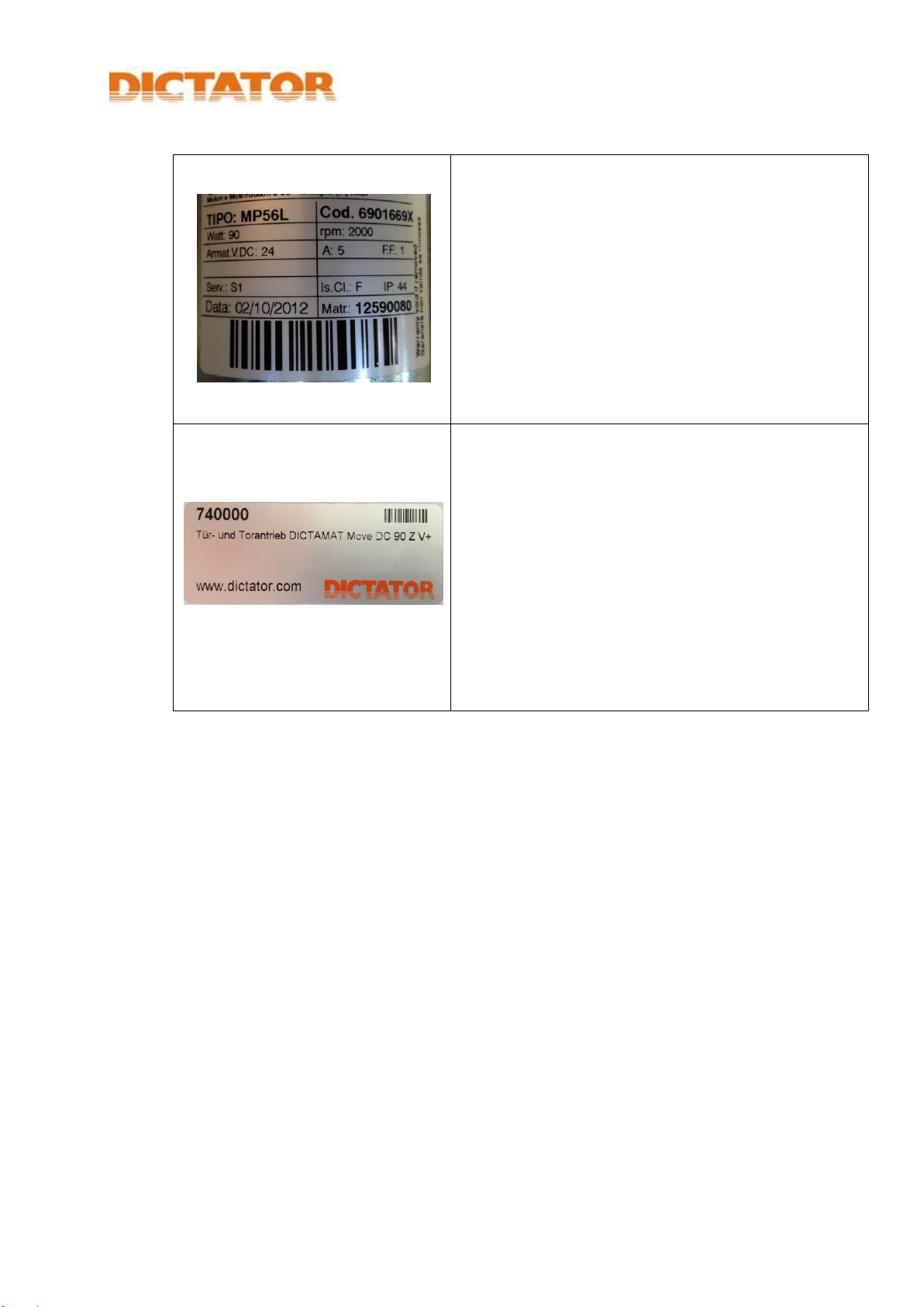
2.5 Explanation of the device’s marking
The Operating System
Translated User Manual MultiMove drive system MultiControl control system Version 2020-07 page 12 of 35
Rating plate of the motor
Rating plate with
motor rating
nominal speed rpm
voltage
type of protection
serial number
date of manufacture
Rating plate of the
operating system
Rating plate with
system number
system name*
*Structure of the system name:
name of the operator
tension
power
power transmission
dimensioning of the gearbox

Safety
Translated User Manual MultiMove drive system MultiControl control system Version 2020-07 page 13 ׀35
3Safety
The personnel of the machine builder has to carefully and completely read and
understand this user manual before they start to mount and put into operation
the operating system. This user manual contains all important information
necessary to prevent personal and material damage, to guarantee a trouble-
free operation and not to affect the environment.
Carefully observe all safety advices and other advices, demands and
information given in this user manual.
Besides the advice in this manual, the generally accepted safety and
accident prevention regulations have to be followed.
Carefully keep this user manual during installation and initial operation
within striking distance of the machine.
Observing this user manual is the condition for a trouble-free operation and
the settlement of possible legal warranty claims. Defects due to not obeying
the user manual void any warranty claims. The manufacturer or distributor
will assume no liability for subsequent damages and for damages to
property or persons due to wrong operation or not obeying the safety notes.
The limit values given in the technical data must never be exceeded.
3.1 How to act in case of an emergency
(1) Should the situation arise, stop the movement:
Trip the EMERGENCY-STOP.
(2) Switch the machine to neutral:
Switch off the mains switch of the machine.
(3) Provide a safeguard to prevent the machine being reclosed
unintentionally.
(4) Request all people to leave the dangerous area.
(5) Secure the dangerous area.
(6) Inform the responsible superior.
(7) Rescue injured persons from the dangerous area if this is possible without
endangering yourself.

Safety
Translated User Manual MultiMove drive system MultiControl control system Version 2020-07 page 14 of 35
3.2 Intended use
The operating system has specially been designed for mounting on horizontally
moved sliding elements (without incline) and may only be used for such
applications. The weight and the dimensions must not exceed the values given
by the customer.
The operating system may only be mounted on sliding elements which
meet the relevant standards.
The control system may only be put into operation when the machine (the
complete installation) into which the operating system is integrated, meets
all legal demands.
The operating system may only then be used according to the intended use
when the machine builder has satisfied all demands regarding the safety
of the operating system that are still open, see 3.4 Responsibilities of the
machine builder.
when the machine (the complete installation) into which the operating
system is integrated, meets all the legal demands.
when all the protective devices which the machine builder has planned
together with the operating system, have been installed correctly and
function properly.
after the personnel of the user has received an initial training by the
engine builder.
Personnel who will have to use or work with/on the operating system has to
have the qualification necessary for the respective task, see 3.5
Qualification of the personnel requirements.
3.3 Foreseeable use
The operating system must not be altered or modified in any way. This
operating system may not or only after consulting be used on vertically moved
sliding elements (lifting gates, sectional doors). The operating system must not
be used on private garage doors, sectional doors and swiveling doors. The
limits (weight, dimensions) given by the customer must not be exceeded.

Safety
Translated User Manual MultiMove drive system MultiControl control system Version 2020-07 page 15 ׀35
3.4 Responsibilities of the machine builder
According to the Machinery Directive (2006/42/EG) the fitter who motorizes a
sliding element is subject to the same responsibilities as the machine builder
and therefore has to do the following:
Issue the technical documentation which has to include the documents
mentioned in the annex VII of the machinery directive.
Issue an EC declaration of conformity in accordance to annex II and attach it to
the machine.
According to article 16 of the machinery directive apply the CE label to the
automated sliding element.
3.4.1 Technical demands
Connection of the power supply of the control system and the possibly to
be installed main switch in accordance with the relevant standards by a
qualified electrical technician, including acceptance test and necessary
measurements.
In case of installations with a stationary mains connection, an all-phase
main circuit breaker with corresponding pre-fusing (fault current breaker,
overload protection) has to be provided.
Compliance with the maximum admissible parameters (mass, speed, travel
distances) specified in the technical data.
Control of the smooth operation of the sliding element before mounting the
door operator. It must be possible to move the sliding element with the
forces specified in the technical data of the operator.
The sliding element must have on both sides sufficiently strong mechanical
final stopping devices.
The noise emission of the operating system (without considering the
complete installation) is less than 70 dBa. After having installed the
operating system in the installation, a sound measurement has to be
performed. If necessary, suitable noise control measures have to be taken.
Installation of all necessary safety elements in accordance with DIN EN
12453 including the measurements of the force prescribed according to EN
12445.
Making sure there is a protective guard for moved or rotating parts of the
system (up to a height of 2.5 m above the floor).
Sufficient stability of the fixing points of the operator components.
Making sure that all parts provided on site (sliding element, rail, supply
lines) comply with the applicable standards.

Safety
Translated User Manual MultiMove drive system MultiControl control system Version 2020-07 page 16 of 35
3.4.2 Demands on the user information for the operator of the machine
It is the machine builder’s responsibility
to amend the information in this user manual according to the results of his
risk assessment and the safety measures taken by him
and to decide which of the information contained in this user manual is
relevant for the operator of the machine and has to be passed on to him.

Safety
Translated User Manual MultiMove drive system MultiControl control system Version 2020-07 page 17 ׀35
3.5 Demands on the qualification of the personnel
3.5.1 Who may what?
The operating system may only be built into the machine, connected and
put into operation by instructed and qualified persons.
Only a qualified electrical technician may work on the electrical system. If
there is no such person available, a specialist firm has to be charged
with the realization.
After its installation in the machine, only instructed persons may use the
operating system and only qualified persons may maintain it.
Only a qualified electrical technician may work on the electrical system. If
there is no such person available, a specialist firm has to be charged
with the realization.
3.5.2 Definitions of the required skills
Instructed person
As an instructed person is regarded somebody who has comprehensively
been instructed on the safe use of the machine by the machine builder or
the operator of the machine.
Qualified person
As a qualified person is regarded somebody who due to his relevant
technical (preparatory) training and/or due to his relevant experience can
recognize risks and prevent hazards which may occur during his work.
Qualified electrical technician
As a qualified electrical technician is regarded somebody who due to his
professional training, knowledge and experience and his knowledge of
relevant regulations can assess and perform the jobs assigned to him and
who independently can recognize possible risks.

Safety
Translated User Manual MultiMove drive system MultiControl control system Version 2020-07 page 18 of 35
3.6 Personal protective equipment
Always wear safety shoes according to EN ISO 20345, category S1 (A+FO+E)
when working with or on the operating system:
antistatic
oil and petrol resistant sole
energy absorption in the heel area
steel caps.
Always wear oil resistant work gloves according to EN 388 when performing
tasks which require a hand protection.
3.7 Conditions of the surroundings
Normal industrial surroundings, dry and dust-free
No hazardous surroundings
When outside operation, only underneath a cover provided by customer
Admissible operating temperatures for operation : -15° to +40 °C
Admissible operating temperatures during transport and storage:
-15° to +40 °C
Admissible air humidity: relative air humidity 20 –80 % non-condensing.

Technical Data
Translated User Manual MultiMove drive system MultiControl control system Version 2020-07 page 19 ׀35
4Technical Data
4.1 Dimensions and weights
Packed state
Dimensions (length x width x
height)
Control system + operator +
accessories
620 x 340 x 270 mm
Weight
max. approx. 30 kg
4.2 Electrical system
Rated input voltage
230 VAC, 50 –60 Hz
Power consumption
max. 6 A
Secondary output voltage
24 VDC or 28 VDC in case of a version with
emergency power
Secondary total load
max. 1 A per output, total max. 2 A
Emergency power capacity
28 VDC, 7 Ah
Output voltage of motor
230/400 VAC (3-phase) or 24 VDC
Power rating of motor
max. 0.37 kW AC / 200 W DC
IP rating
IP 54
Recommended fuse
protection
B 16 A

In-House Transport, Unpacking
Translated User Manual MultiMove drive system MultiControl control system Version 2020-07 page 20 of 35
5In-House Transport, Unpacking
5.1 Safety
WARNING
Squeezing hazard for hands and feet
The door operator can topple over and/or fall down during transport. This can
result in severe crushing injuries of hands and feet. There can be sharp edges on
the operator and the accessories. They can cause lacerations.
Wear work gloves.
Transport the door operator and the control system only with lifting and
transporting devices being sufficiently dimensioned.
5.2 Transporting and unpacking the drive system
(1) Use appropriate means of transport for transporting the door operator and
the control system (pallet truck).
(2) When opening the cardboard, don’t damage the operator. Use a knife with
a short blade.
(3) The electric cables must not be damaged during unpacking.
(4) Dispose properly of the packing material.
(5) Check if the unpacked parts are complete (components included).
(6) Check the unpacked parts for damages, especially the electrical cables.
(7) Lifting of the door operator: In three sides of the casing of the operator are
provided M10 threads. To these threads can be fixed suitable sling
devices (eyelets) to lift the operator.
(8) In case the door operator should be mounted at a higher height, we
recommend using a suitable hoisting platform.
Table of contents


