Table of Contents
Updated 1/12/23
INTRODUCTION 1
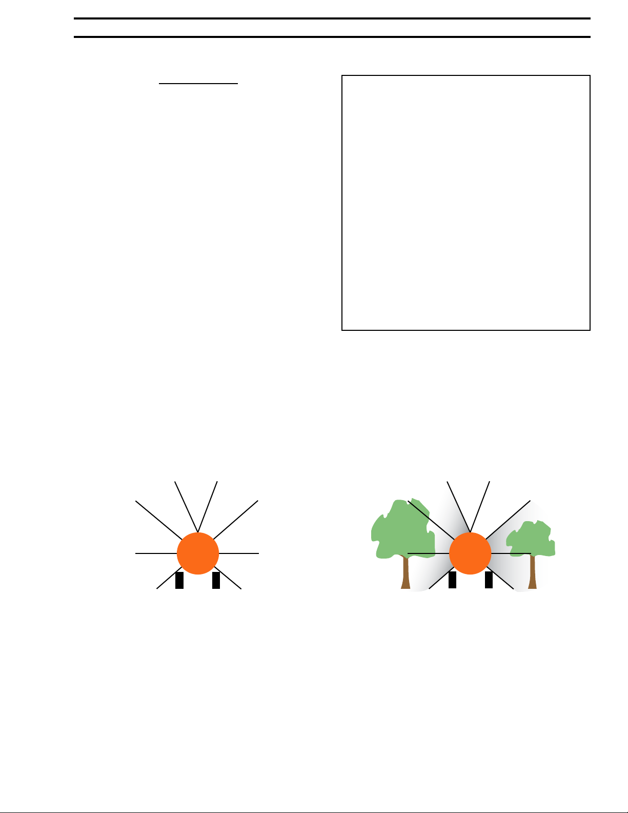
About Sonic Spray’s Zones 1
OPERATOR INTERFACE DISPLAY 2
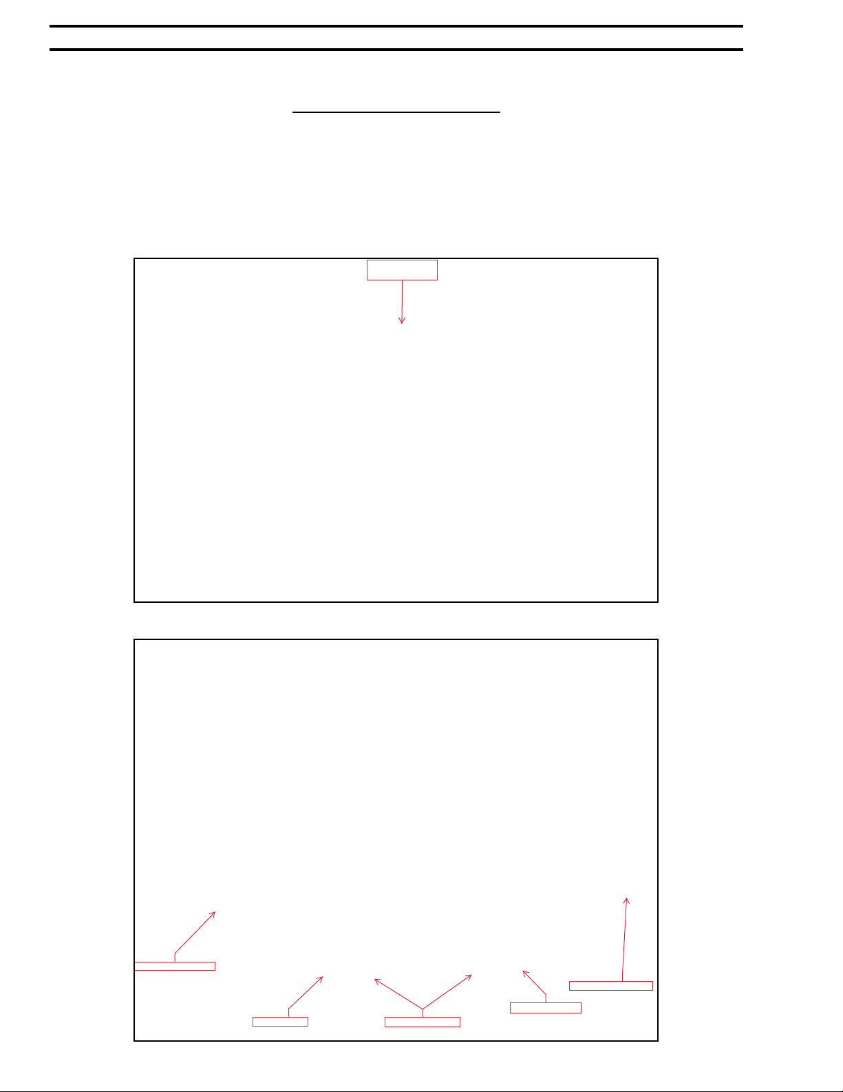
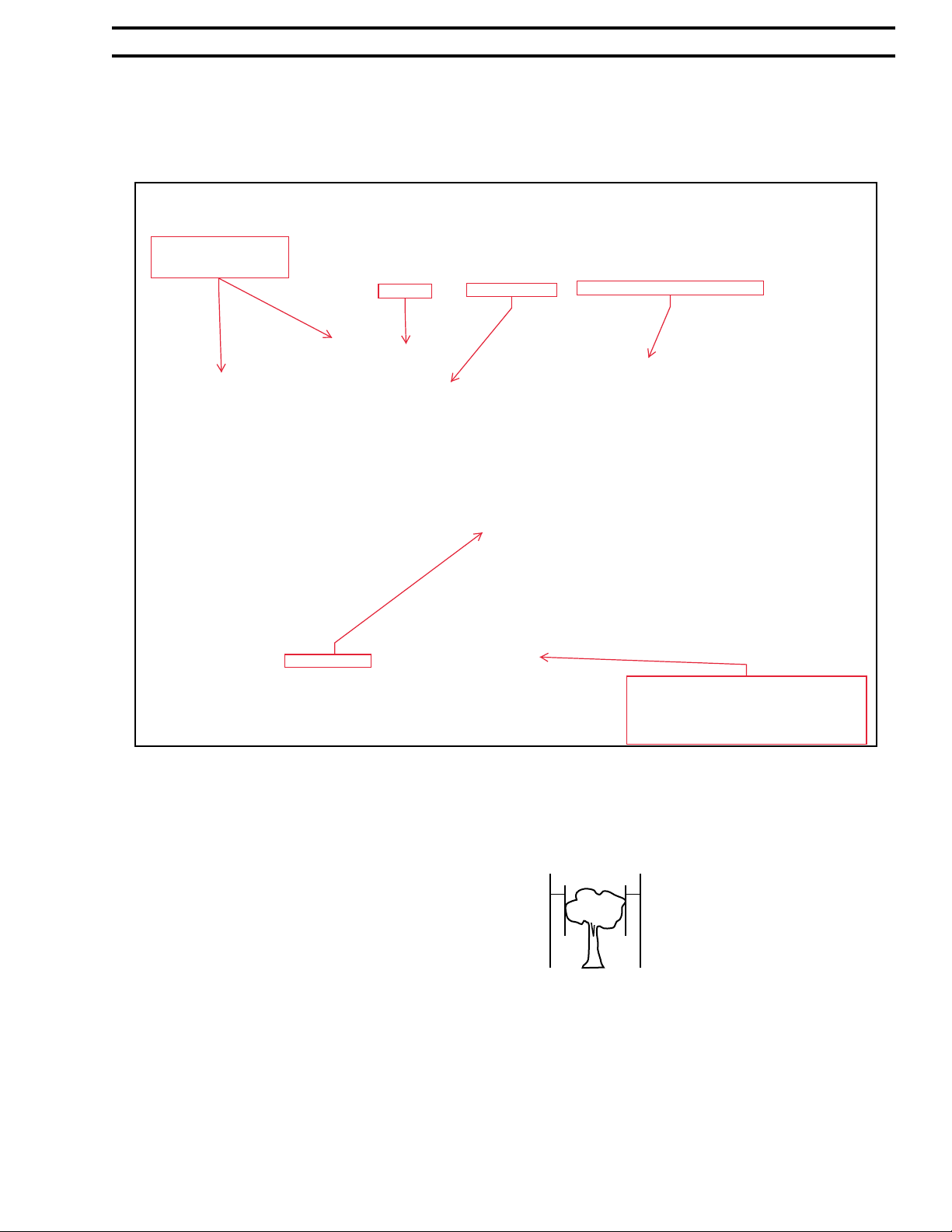
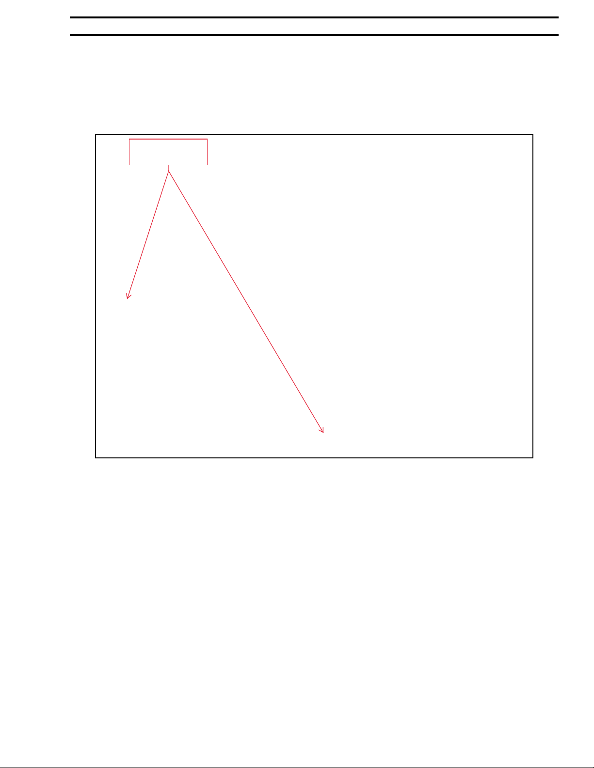
Overview of Sonic Spray’s Operator Interface 2
OPERATION 11
MAINTENANCE 12
Basic 12
Maintenance of Solenoid Valves 13
Winterizing 12
INSTALLATION ON TRACTOR 14
KIT INSTALLATION ON SPRAYER 15
Display Controller CAN Tool 19
Front of Sprayer Electrical Connecons 22
Speed Sensor and Parts 20
Speed Sensor Harness to Main Connecon 21
Ultrasonic Electrical Connecons 16
Valve Installaon 18
Valve Mounng Reference 17
Zone Diagram 15
TROUBLESHOOTING 23
Ground speed not working 23
No Sync Warning 24
Power ON Status 23
Power to control on green light illuminated but display not
working 23
Sonic Spray will not power up 23
Target Indicator Funcons 24
Target Status & Near MIN 23
Ultrasonic 1 not working 23
Ultrasonics 23
Valve not opening 23
Valve not shung o 23
ELECTRICAL 25
Baery to Controller 32
Harness Display to Controller 29
HARNESS, VALVE 6 ZONE FOR AIR-O-FAN ENGINE DR 30
HARNESS, VALVE 8 ZONE FOR AIR-O-FAN ENGINE DR 31
Power Supply 25
Speed Sensor 28
Ultrasonics 26
Valve Harness Sprayer, 6 Zone 33
Valve Harness Sprayer, 8 Zone 34
Valve Harness Sprayer to Control 35
Valves 27
PARTS 36
ASCO Valves & Repair Kit GTS 11006 39
Baery Connecon Parts 46
Clamps 36
Display Controller and Parts 44
Harnesses 42
Harness, Proximity & parts 43
Mount for Display Controller and Parts 45
Rears Front Panel and Parts Reference 50
Rears Front Panel and Parts Reference connued 51
Sensors for 50 Long Range Sonic Spray 38
Sensors for Standard Range Sonic Spray 37
Sonic Spray Main Enclosure 47
Speed Sensor and parts 49
Tork Valve & DIN Harness GTS 11350 40
Tork Valve Repair Kit 41
Wheel Speed Assembly 48
GVF WARRANTY 52