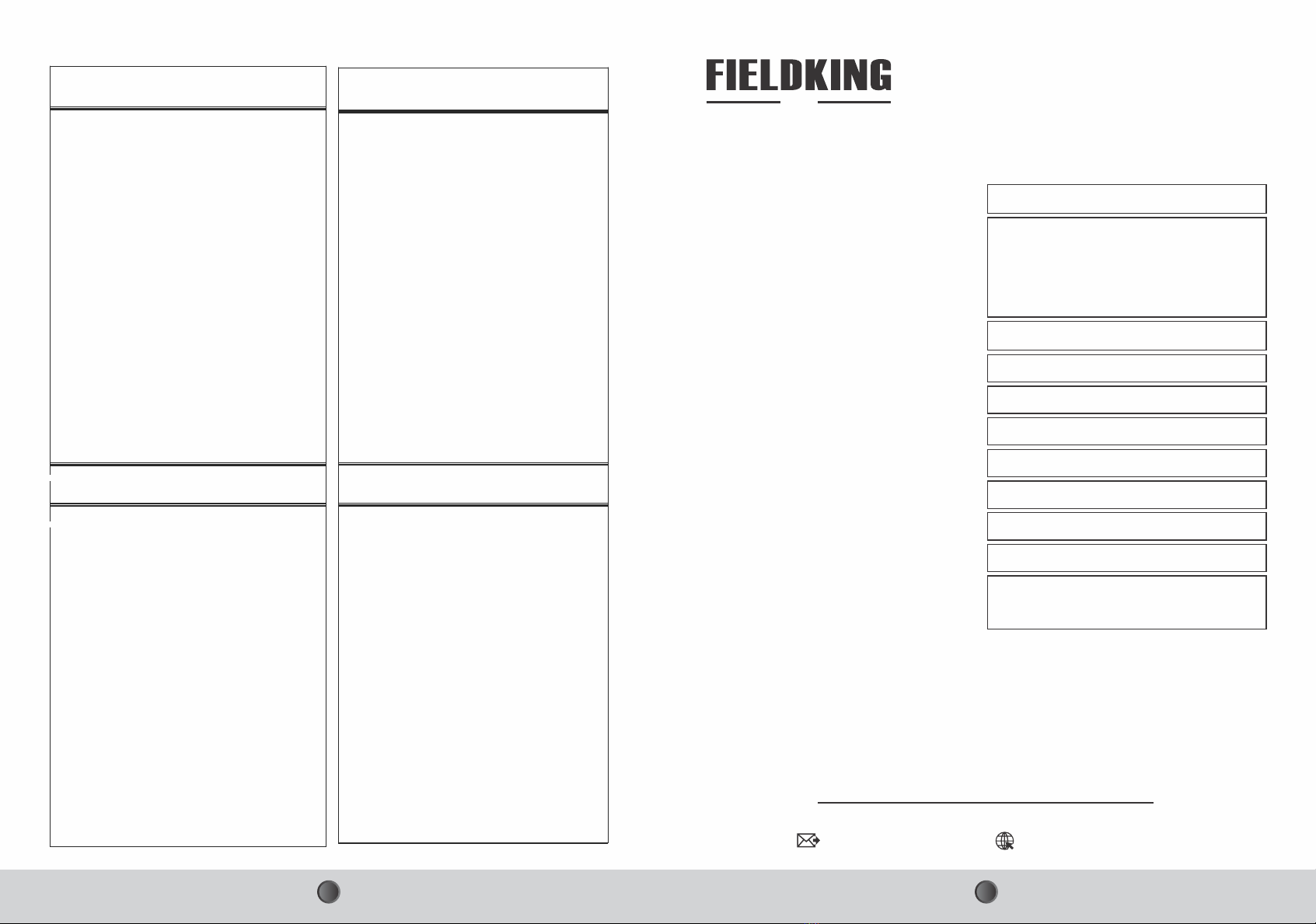
FIELDKING No Till Multi Crop Drill User manual

No Till Multi Crop Drill
Operator Manual
† Service Manual
† Part Catalogue
†
Seeding & Plantation
Post Harvest
Harvest
Crop Protection
Landscaping
Tillage Haulage
Solutions...
12-08-2019
USA
960 Holmdel Road Suite 2-02, Holmdel, NJ 07733, USA
[email protected], www.fieldking.com
FIELDKING USA, INC.

You have invested in one of the best implements of its type in the market today.
Should you require additional information or assistance, please contact us.
The care you give your “FIELDKING USA” implement will greatly determine your
satisfaction with its performance and its service life. A careful study of this manual
will give you a thorough understanding of your new implement before operating.
If your manual is lost or destroyed, “FIELDKING USA” will be glad to provide you a
new copy. Visit to nearest dealership & get a copy. Most of our manuals can also be
downloaded from our website at www.fieldking.com.
As an authorized “FIELDKING USA” dealer, we stock genuine “FIELDKING USA”
parts which are manufactured with the same precision and skill as our original
equipment. Our trained service persons are well informed on methods required to
service “FIELDKING USA” equipments and are ready to help you.
CONGRATULATIONS!
YOUR AUTHORIZED
FIELDKING USA DEALER
BECAUSE “FIELDKING USA” MAINTAINS AN ONGOING PROGRAMME
OF PRODUCT IMPROVEMENT, WE RESERVE THE RIGHT TO MAKE
IMPROVEMENTS IN DESIGN OR CHANGE IN SPECIFICATION
WITHOUT INCURRING ANY OBLIGATION TO INSTALL THEM ON
UNITS PREVIOUSLY SOLD. BECAUSE OF THE POSSIBILITY THAT
SOME PHOTOGRAPHS IN THIS MANUAL WERE TAKEN OF
PROTOTYPE MODELS, PRODUCTION MODELS MAY VARY IN SOME
DETAIL. IN ADDITION, SOME PHOTOGRAPHS MAY SHOW SHIELDS
REMOVED FOR THE PURPOSE OF CLARITY. NEVER OPERATE THIS
IMPLEMENT WITHOUT ALL SHIELDS IN PLACE.

2. Operate, lubricate, assemble and maintain the equipment in accordance with all
instructions and safety procedures in this manual.
5. All costs incurred by the dealer for traveling to or transporting the equipment for
warranty inspection and claims will be borne by the customer.
1. Read and understand the information contained in this manual.
4. Return the equipment or parts to the authorized “FIELDKING USA” dealer, from
where it was purchased, for service or replacement of defective parts that are
covered by warranty. (The “FIELDKING USA” Factory may inspect equipment or
parts before warranty claims are honored.)
3. Inspect the equipment and replace or repair any parts that are damaged or worn
out which under continued operation would cause damage, wear to other parts,
or cause a safety hazard.
PURCHASER / OPERATOR’S RESPONSIBILITY
This manual contains valuable information about your new “FIELDKING USA” No
Till Multi Crop Drill. It has been carefully prepared to give you helpful suggestions for
operating, adjusting, servicing and ordering spare parts.
Keep this manual in a convenient place for quick and easy reference. Study it
carefully. You have purchased a dependable and sturdy No Till Multi Crop Drill but
only by proper care and operation you can expect to receive the service and long life
designed and built into it.
Sometime in the future your No Till Multi Crop Drill may need new parts to replace
which are worn out or broken. If so, go to your dealer and provide him equipment’s
detail like model and part number.
Serial No. ___________________________________________
Date of Purchase _____________________________________
Name ______________________________________________
Purchased From ______________________________________
Model No. ___________________________________________
TO THE PURCHASER
CUSTOMER INFORMATION

1.1. Introduction
1.3. When the warranty becomes void
1. TECHANICAL DATA
1.2. Warranty
2.8. Precaution for use
2. Major Components and their Description
2.1. Frame
2.6. Depth-control packer roller
3. Tips For Manufacturers Operation, Maintenance and Repair
2.4. Seed metering device
2.5. Power transmission unit
3.1. Repair
1.4. Usage and instruction
3.2. Planting operations
1.6. Re-assembly parts
1.5. Maintenance
2.2. Disc openers
2.7. Hitch points
2.3. Seed boxes
3.3. Maintenance and repair
4. Troubleshooting
INDEX

21
1. TECHNICAL DATA
1.1 Introduction
No Till Multi Crop Drill
The purchaser may only make the claims under warranty. When he has complied with the
warranty conditions in the supply contract.
Besides the cases specified in the supply agreement, the warrantee shall in any case
become void:
When the implement is delivered, check that it has not been subjected to damage during
transport and that the accessories are in a perfect condition and complete.
Any claims following the receipt of damaged goods shall be presented in writing within 8
days from the receipt of the goods.
This handbook contains the use and maintenance instructions with a list of spare parts of
No Till Multi Crop Drill.
1.2 Warranty
Compliance with instructions given in this handbook is also important since manufacturer
declines all and every responsibility for damage to persons or property cause by
negligence and failure to comply with these instructions.
Fieldking USA No Till Multi Crop Drill is high performance drill designed to sow seed of
wide variety and size. Due to its precise metering system this is achieved accurately and
economically.
Regular and satisfactory operations together with economic and long lasting use of the
implement depends upon the compliance with instructions given in this book.
1.3 When The Warranty Becomes Void
4. No warranty will be given if the service and greasing is not done on time.
2. When repairs made by the customer without authorization from the manufacturer or
owing to installation of spurious spare parts, the machine is subjected to variations and
the damage can be ascribed to these variations.
1. Check seed boxes, there should not be any metal piece or any hard material capable of
damaging metering system.
1. When the implement has been used beyond the specified power limit like (Tractor Horse
Power)
3. When the user has failed to comply with the instructions in this handbook.
1.4. Usage And Instructions :
3. Before sowing the front and rear disc should be in same horizontal
plane, this leveling of disc can be adjusting the Top Link of tractor.
2. Place the drill on leveled surface to adjust the depth of sowing as
desired. By adjusting the height of side packer roller and we can get
the desired depth of sowing. For the vertical moment of balancing
packer roller a special pin arrangement is provided. By removing pin
we can adjust the height of packer roller. As we lower the wheels depth
decreases and as we lift the wheel the sowing depth increases.
4. Seed Metering Method : For desired quantity that is to be sown can be adjusted with the
help of grain index plate that is fixed on the seed box. On the grain index plate there is
equal distance holes. There is lever that is move on the above said holes of index plate. A
we step one hole to right side 22Lbs.- Acre can be decreased as we move lever to the left
side. As we move 1 to 2 No. Seed quantity can be increased by 22Lbs. The above said
quantity is for wheat, corn.
Fig.-1
No Till Multi Crop Drill is relatively simple machine. The proper lubrication of the machine
wherever is needed is highly important if satisfactory performance and long life are to be
ensured1. Oil and grease the all lubricating parts daily before sowing (All wheels, shaft
and grease cup etc.)
2. There is a reel on the seed shaft that is beneath the seed box,
grease this reel also, which is very important for the smooth working
of seeding mechanism.
1.5. Maintenance
4. After regular intervals clean and paint both boxes.
5. To adjust row to row distance of tynes loosen the two ‘’U’’ clamps of
the tyne and set the distance as desired and than tighten the clamps
fully (Fig-6).
3. After sowing but before storing the seed take it to any service station
so that the drill can be cleaned / washed through with the high
pressure water spray. But remember after the spray of water, apply
diesel on both boxes with the help of brush or peace of cloth to prevent the box from
rusting. It is important that the No Till Multi Crop Drill should be parked in covered area and
away from sunlight.
6. Before re-using machine in next sowing season, all moving &
rotating parts should work freely/properly.
Fig.-5
Fig.-6

43
1.6 Re-Assembling of different parts of machine to right position for its proper working :
1. Central Wheel : Central wheel is fixed inside the frame : take it out by loosing the bolt. It
should be fixed in the center of machine at front. Fix it as shown in pictures.
2. Seed Handle : The seed handle is bolted under hopper.
Loose the bolt and take the handle out. Now as shown in
figures fix the handle in shown position. Bolt the handle in
same hole but in right position. Do not forget to check nut it
(Use double nut it).
3. Rear Platform : Fit the plate-form in horizontal position as
shown in figures and bolt it with frame.
Fig -8 (c) Fig -8 (d)Fig -8 (b)
Fig -8 (a)
2.2 Disc Openers:-
The No Till Multi Crop Drill has 9-13 inverted disc’s openers depending on the model or
brand. These can be spaced as needed in different crops. These disc type openers when
attached to a disc open a narrow slit 1.2"-2" wide. The cutting portion of the disc’s openers
is made by using 0.1" thick disc. The disc’s opener is welded to the mild flat steel shank
(straight leg standard mounted with disc’s slit openers). The discs can be of “welded on” or
“bolted on” or even “knock down” type. The disadvantage of “welded on” disc is that they
require machine shop for replacement, whereas, a farmers himself can replace the other
two types of disc.
2.1 Frame:- 2.4"×2.4" sq. welded together to provide the desired strength and rigidity. This is
true in a drill of 9 discs but in 11-discs drill, the length of frame is about 5'9".
2. Major Components and their Description
7. To ensure the proper working oil all the moving/rotating parts like
seed shaft, front & side wheels and then rotate the front wheel with
hand. Check that whether the parts are working properly or not. In
case the parts are not working properly oil the moving parts
especially in the router's hole in the fluted rollers (seed shaft). And
after some time rotates the front wheel with hand again to check that
is it moving/rotating freely (Fig-7).
Fig.-7
2.3. Seed Boxes
Seed boxes, made of mild steel sheet (0.07" thick), are mounted
side by side on the frame, in front and seed box in the rear. Box
dimensions can vary but these generally depend upon the
effective width of the machine and will increase with the increase
in the number of the disc’s openers. For example in case of 11-
disc, the length of seed boxes will be around 5'10". Inner view of
(a) Seed.
2.4. Seed Metering Device
Seed metering device has the following components
2. Measure the effective width of coverage in meters of the drilling machine by multiplying
number of furrows with spacing.
3.2. To cover distance l, the drive wheel has to take ‘n’ turns i.e. = l/D
1. Measure the diameter (D) of the drive wheel and calculate its circumference i.e. D in
meters.
Calibration of seed-drill (in Laboratory)
3. Then distance/length (L) to cover one hectare is calculated by dividing 10000 m2 (area of
one hectare) by effective coverage
3.5. Weigh the quantity of seed dropped from each opener and record on the data sheet to
know the variation in different rows, if any.
3.4. No Till Multi Crop Drill Raise the seed drill so that drive wheel becomes free to be turned.
Put a chalk mark on the rim of the wheel. Fill the seed box, set the seed rate adjusting lever
and rotate the wheel for ‘N’ turns.
3.1. The distance (l) i.e. l/100th of a hectare will be equal to L/100 in meters.
3.3. Allowing 10% slippage, the distance can be covered in ‘N’ turns i.e. = (n–0.1 n)
Fig-11(a) Seed Hole

65
2.5. Power Transmission Unit
1.Drive wheel
4.Sprocket
Power transmission unit (Fig.14) has the following main
components:
2.Shaft
3.Idler
Fig. 14. Power transmission unit
and its main components.
Example, say
* Then distance/length (L) to cover one hectare will be =(10,000/2490)=13176'
* Circumference of the drive wheel = 1'4"
Put seed in the boxes. Set the rate control adjustment lever as prescribed by the
manufacturer.
* Width of machine = 8'2"
* To cover distance (l), the drive wheel has to take turns (n) = 40.06/0.4=100.15
* As we know area of one hectare=17639 (sq. ft.)
* The distance (l) i.e. 1/100 of hectare will be = 131'
* Allowing 10% slippage, the distance (l) can be covered in ‘N’ turns (n–0.1n) = 90.135
(approx.).
Roller chain
The power required to operate the seed metering devices is provided by a floating type
lugged drive wheel 1'4" in diameter and 4" in width through chain and sprockets. However,
size of the drive wheel may vary in different models. Fourteen lugs each of 1.2" height at
an angle of 900 are provided on the ground wheel to avoid slippage. Wheels are of iron
closed type or with rubber on them for better traction. This ground wheel or drive wheel is
attached to the frame in front. Traction can be adjusted through a groove and spring as
desired. Attachment of drive wheel in the front side of the frame sometimes creates
problem in the free movement of wheel due to soil or
stubble blockage or due to its location being very near to
the hook of the tractor. A motorcycle roller chain of 0.5" pitch
with 14 and 37 number of teeth on the mild steel sprocket is
provided for power transmission from the drive wheel to
seed metering devices. Power from ground wheel is
transmitted to a shaft (1:1) (Fig. 15) mounted on front
frame. From this shaft power is transmitted to seed
metering shafts (2.5:1) through the chain sprocket
arrangement. However, size of roller chain and sprocket
can vary in different models as per requirements. An idler
has been provided to tighten or loosen the chain for its smooth running.
Fig-15 Drive Wheel attached
on the Front Side
2.6. Depth-Control Packer Roller
The size of these wheels may vary in different models. With
the help of depth adjusting pin (Fig.16b), these wheels can
be raised or lowered to increase or decrease the depth of
seeding, respectively. The depth of seeding in case of
wheat varies from 1.2"–2". However it can be adjusted as
per requirement.
If there is a large amount of loose straw in the field, these
depth wheels can get jammed with the straw. If this
happens, the depth-control wheels can be removed and
depth control maintained with the tractors’ hydraulics, to
reduce straw jamming.
2.7. Hitch Points
The drill has three standard hitch points; two lower
and one upper (Fig. 17). The machine is attached
to tractor through these three hitch points with the
help of link pins. The top link hitch point also helps
in leveling the machines
Fig. 17. Hitch points.
(Fig. 16a) Depth-control packer roller
(Fig. 16b) Depth-adjusting pin
2. Conversely, No Till Multi Crop Drill machine does not work well in fields where moisture
levels are too high (wheel slippage) and under such situations care must be taken to
prevent blockage of seed tubes.
3. Heat stress at grain filling is less in late winter season when temperature begins to rise.
The overall growth period of crop is more in early sowing.
4. Longer duration varieties such as PBW 343, HD 2687 having better vigor at early growth
and profuse cultivating cover the soil surface and are more competitive with weeds.
2.8 Precautions For Use
1. Sowing of wheat with No Till Multi Crop Drill is best accomplished when soils have 3-4%
more moisture than under conventional method. Germination of wheat and corn crops is
adversely affected if the soil is too dry.
5. The quantity of seeds are use in hopper by standard.

87
8. Irrigation immediately after sowing of wheat is not recommended. If needed, post-sowing.
9. Operator only sit on stand and not give the pressure of hands on machine.
6. When weed pressure is not a factor, tilling of soil is not needed and reduced tillage (1–2
ploughings) and cross-sowing methods do not provide any additional advantage over
seeding. Rather these methods may reduce germination and yield and induce
germination of P. minor besides increasing the cost of cultivation.
3. TIPS FOR MANUFACTURERS, OPERATION, MAINTENANCE AND REPAIR
3.1 Repair
2. Frame shanks and disc’s openers should be strong and made of proper material.
7. It has been observed that farmer can skip the use of herbicides when zero tillage and
alternate herbicides are carefully integrated for 3–4 years.
1. Machine should be of good quality and manufactured according to appropriate design
specifications/drawing.
3. Provision should be made for replaceable parts on wear and tear.
8. Packing, handling and transportation should be proper.
9. Pooled service should be provided free of cost for replacement of parts or complete
machine, if there is any defect or breakage during transportation.
10. Manufacturer should incorporate required modification based on seed back from time to
time.
5. Testing before marketing should be ensured at manufacturer level.
6. Spare parts, critical components, nuts and bolts or clamps should be of high strength and
standard quality.
Following points must be kept in mind before actual planting operation:
4. There should be stress-free and proper alignment of components without any inbuilt
stress assembly.
7. Minimum tool kit should be provided.
3.2 Planting Operations
1. Seed should be of good quality and free from dirt and dust.
2. All the nuts and bolts, rollers should be thoroughly checked, defective parts should be
replaced and nuts/bolts properly tightened.
Chain sprocket of metering mechanism should be properly aligned. Appropriate tension in
the chain may be kept for free movements of seed metering shafts. If there is any noise
during operation, stop the machine and check it.
4. Fluted roller shaft should move freely, otherwise the rollers may be broken.
3. Seed boxes, fluted rollers, seed metering shaft and controlling bottom plate (having
triangular holes) should be thoroughly cleaned.
5. Seed cups should be thoroughly cleaned and obstruction if any, must be removed.
6. Ensure that plastic pipes do not have excessive bend. This will block the free flow of seed
in tubes.
3.3.1. Seed Boxes
The boxes should be thoroughly cleaned as these may rust very fast due to environmental
moisture. This will damage the boxes and machine will not be useful for the next crop
sowing season. The boxes must be cleaned as under:
1. Raise the machine above ground so that the drive wheels move freely
A well maintained and properly adjusted seeding machine gives trouble free service for a
long time. It also helps in timely completion of operations The following important points
may be kept in mind for the maintenance and repair of various components of the seeding
machines.
* Disc assembly should be fitted on the frame according to the requirement (row to row
distance) of the crop. There should be no crossing or twisting of disc assembly.
* Fill the seed boxes and calibrates the machine. Ensure that seed drill is set at desired
seed rates. This will ensure proper metering of seed and result in excellent germination,
good crop stand and higher yield.
2. Remove seed from boxes.
3. Open the flow gates of seed cups.
3.3 Maintenance and Repair
4. Rotate the drive wheel till the seed from different seed cups are emptied. Clean the boxes
and cups with the help of a cloth or brush.
5. Wash the machine rollers/seed boxes with diesel to avoid rusting.
3.3.2. Drive/Power Transmission System
6. Apply lubricating oil at appropriate places (bushes and sides of metering rollers).
1. Drive wheel should move freely. If it is jammed, then apply grease or put oil in its bushes. If
axle of wheel is bent or worn out, replace it.
For maintenance of drive system/power transmission system, keep following points in
mind:-

109
2. Drive wheel should be round, if it is bent then repair it.
7. Seed boxes should be thoroughly cleaned for free movement of seed shafts.
5. Seed shafts should move freely. If these are jammed due to rusting, then clean and apply
lubricating oil/grease in the bushes.
3. Sprockets of drive wheel and seed shafts (seed boxes) should be properly aligned.
4. All sprockets should be properly tightened on their shafts so that these may not move
freely on these shafts.
6. Bent drive shafts should be repaired or replaced.
8. Chain and idler sprocket should be properly tightened so that proper chain tension is
maintained and mechanism moves freely.
Usually fluted roller type seed metering mechanism is used in these seeding machine. It
should be repaired and maintained as under.
4. Remove metering rollers from the seed cups and replace broken rollers and notched
plates.
7. Put the rollers on the shaft and put again on the seed box.
2. Remove the nuts/bolts of all the seed cups.
9. Worn out parts, loose, broken and worn out bushes should be replaced.
8. Complete system should move freely and rotate the sprocket till appropriate seed rate is
achieved from all the rollers.
3. Old/bent tubes should be replaced.
3.3.3 Seed Metering Mechanism
5. Take out the shaft on one side. All rollers will come out of seed cups.
1. Side plate of seed metering shaft sprocket should be removed by loosening nuts/ bolts.
3. Remove pins of all the fluted rollers.
6. During refitting of rollers, it must be ensured that all the rollers are at equal distance in the
seed cups. If distance is different, then put washers to achieve equal distance.
3.3.4 Seed Tubes
These are mostly plastic tubes connected to seed cups and their lower ends are
connected to seed boots.
1. Tubes should be connected to seed cups with the help of clamps so that these may not
come out during field operation.
2. Tubes should be protected from bending and breakage.
2. Machine should be protected from rain, dirt and dust etc. during its storage.
4. TROUBLESHOOTING
3.3.5. General
1. All the components of the machine should be painted
4. Users training will lead to improvement in the performance of the machines.
4. Excessive bend in the tubes should be avoided otherwise the bend will cause obstruction
in free flow of seed and results in non-uniform application of seed in the field.
3. Moving parts should be greased/oiled at regular intervals so that the machine gives a
trouble free service for a long time.
Seed not placed at
desired depth
Seed is not dropping
from disc’s openers
PROBLEM
Adjustment of depth control
wheel In not proper
CAUSE
1.The seed box is empty.
4.The drive wheel does not
Touch the ground
2.The disc’s opener or seed
delivery Tube is blocked by
soil/mud or seed delivery
pipe bent
5.Broken chain/sprocket
3.Seed metering wheel gem
Refill the seed box
REMEDY
Delivery tubes
Properly adjust the depth of furrow
openers with the help of depth
control wheel
Clean mud out of the opener and/or
Clean the seed from orange box
Change the broken part
Lower down the hitch to get the
drive wheel in contact with the land.
Seeding among
different rows/disc’s
openers
Unequal depth of Improper three point
linkage balancing
Put the machine on a fairly level
ground and then level all the furrow
openers with the help of top
link/right lower link of the tractor.
CALIBRATION CHART
SPREADING CHART FOR WHEAT’S SEED CALIBRATION (LBS. / ACRE, LBS. / HECTARE)
SEEDS RATE
SEEDS QTY. Lbs. / Acre
SEEDS QTY. Lbs. / Hectare
QTY. KG/ACRE (WHEEL)
ACRE SIZE= 220 (L) X 198 (W) FEET
MACHINE SPREADING WIDTH / 6 FEET
WHEEL SIZE 27"=1 ROUND 8 FEET AREA COVER
NOTE-TRACTOR SPEED KM/H N/A
1
17
42
2
33
81
3
59
146
4
75
185
5
90
222
6
105
260
7
123
304
8
139
343
9
154
380
10
169
417
11
185
457
12
202
497

11 12
No Till Multi Crop Drill Main Assembly
A
1
2
3
4
5
6
7
1 8
9
10
11
12
13
14
15
16
17
18
18
19
20
21
22
24
25
27
26
28
29
20
21
30
31
32
33
34
35
36
37
38
39
40
41
42
43
44
45
75 76
78
64
63
79
23
DETAIL A
46
47
49
48
50
No Till Multi Crop Drill Main Assembly
9 10390112 2
10 10050091 2
11 10160087 10160089 10160090 1
1 HEX. HEAD BOLT M8X1.25X25
SPRING WASHER 8MM
CHAIN COVER ASSEMBLY (DISC SEED DRILL)
CHAIN 10B (45 LINKS)
UCFL BEARING 205 COMPLETE ASSEMBLY
PLAIN HEX NUT M16X2 (5.6 GRADE ) AUTO BLACK
EXTERNAL CIRCLIP 22
SPROCKET 11TX 6 SPLINE (DERIVE SHAFT)
INTERNAL CIRCLIP 65
BEARING 6305 2Z
ROD FOR SEED GUN MOUNTING (DISC SEED DRILL)
10260090 3
2 10270001 3
3 78550063 1
4 10140052 1
5 10050353 2
6 10280121 4
7 10390063 2
8 10170071 1
SR. NO. DESCRIPTION ITEMCODE QTY.
9-TYNE 11-TYNE 13-TYNE 9-TYNE 11-TYNE 13-TYNE
10160099 10160100 10160101
13 78550009 78550010 78550011 1
SEED PISTOL MOUNTING ROD SUB ASSEMBLY (SEED-CUM-SEED)
MAIN FRAME ASSEMBLY DISC SEED DRILL
14 78390036 1
HOOPER ASSEMBLY COMPLETE (SEED-COM-SEED)
15 78390015 78390016 78390017 1
16 78390029 2
17 10260353 2
18 10220078 2
19 10260372 6
20 10270004 20
21 10280090 20
22 10020047 2
23 10020022 6
24 78550062 1
25 10260134 1
26 10270005 13
27 10280005 13
28 78550053 1
29 10260386 8
30 10150102 2
31 10390051 2
32 10050054 2
33 10090079 2
34 11030049 1
35 78550066 1
36 10170073 1
37 10260316 2
38 10020026 4
39 10670013 5 6 7
40 10670014 4 5 6
HOOPER COVER ASSEMBLY DISC SEED DRILL
STOPPER FOR HOPPER COVER ASSEMBLY
HEX. HEAD BOLT M10X1.5X35
TOGGLE CLAMP (HC22) H.CAPACITY 210DAN(FOR SEED DRILL)
HEX. HEAD BOLT M14X2X35
SPRING WASHER 14MM
HEX. NYLOCK NUT M14X2
TILLER PIN 28X145MM WITH HANDLE
LINCH PIN 10MM
3-POINT LINKAGE SUPPORT FLAT ASSEMBLY
HEX HEAD BOLT 16X105X2MM
SPRING WASHER 16MM
HEX. NYLOCK NUT M16X2
3-PONT LINKAGE ASSEMBLY (DISC SEED DRILL)
HEX. HEAD BOLT M14X2X50
BEARING HOUSING CAP (DRIVE WHEEL)
INTERNAL CIRCLIP 47
BEARING 6005
BEARING HOUSING WITH CAP (DERIVE WHEEEL) SEED DRILL
TYRE 4.00-8 TYRE+TUBE+RIM (POWER TILLER)
TYRE AXLE SHAFT SUB-ASSY. (SEED DRILL)
CHAIN TIGHTNER ASSEMBLY WITH SPROCKET 16T (DISC SEED DRILL)
HEX HEAD BOLT M20X65X2.5P
PIN 19X90MM
COMPLETE PISTOL ASSEMBLY (FOR SEED) FRONT FACE
COMPLETE PISTOL ASSEMBLY (FOR SEED) REAR FACE
78390037 78390038
12 1

1413
No Till Multi Crop Drill Main Assembly
3027313233
34
35
51
46
47
27
26
652
27
26 53
20
21 57
55
54
67
56
58
59
SR. NO. DESCRIPTION ITEMCODE QTY.
9-TYNE 11-TYNE 13-TYNE 9-TYNE 11-TYNE 13-TYNE
41 56 7
42 456
43 10020097 38
44 10200056 8 MTR 9 MTR 10 MTR
45 10301146 18 22 26
46 10270002 8
47 10280002 8
48 10280027 36 44 52
49 10270008 72 88 104
50 10260373 36 44 52
51 10260005 4
52 10160086 1
53 78550021 1
54 10260454 10
55 78550061 2
56 10170069 1
57 10140051 1
58 10290155 10290163 10290164 1
59 10300005 2
60 10260363 8
SPLIT PIN 1/8X2.5 INCH
PVC FLEXIBLE WATER SUCTION HOSE PIPE 36 O/Dx31I/D (SEED DRILL)
HOSE PIPE CLAMP 1 INCH
SPRING WASHER 10MM
HEX. NYLOCK NUT M10X1.5
HEX. NYLOCK NUT M8X1.25
PLAIN WASHER 8MM
HEX HEAD BOLT 8X40X1.25MM
HEX. HEAD BOLT M10X1.5X40
ROD FOR DRIVE WHEEL
BUSH FOR DRIVE WHEEL FLAT ASSEMBLY
HEX HEAD BOLT M16X55X2MM (GRADE 8.8)
DRIVE WHEEL HOLDING FLAT ASSEMBLY
SPROCKET 15T X 6 SPLINE (SEED DRILL)
CHAIN 10B (40 LINKS)
MAIN SPROCKET SHAFT (SEED DRILL)
GREASE NIPPLE M10X15X1.5MM (P)
HEX HEAD BOLT M12X50X1.75MM
No Till Multi Crop Drill Main Assembly
COMPLETE PISTOL ASSEMBLY (FOR SEED) REAR FACE 10670014
COMPLETE PISTOL ASSEMBLY (FOR SEED) FRONT FACE 10670013

1615
B
77
61
60
54
62 72
26
27
70
20
21
38
64
63
65
66
67
68
69
37
71
74
73
DETAIL B
48
49
50
No Till Multi Crop Drill Main Assembly
SR. NO. DESCRIPTION ITEMCODE QTY.
9-TYNE 11 -TYNE 13-TYNE 9-TYNE 11-TYNE 13-TYNE
61 10070168 6
62 10390053 2
63 10270003 50 58 66
BUSH FOR PACKER ROLLER MTG. PLATE
EXTERNAL CIRCLIP 47
SPRING WASHER 12MM
HEX. NYLOCK NUT M12X1.75
NYLOCK NUT M20X2.5MM
SPRING WASHER 20MM
OPERATOR STAND ASSEMBLY DISC SEED DRILL
PACKER ROLLER SUPPORT PIPE ASSEMBLY DISC SEED DRILL
PACKER ROLLER ASSEMBLY DISC SEED DRILL
HEX HEAD BOLT M14X60X2MM (8.8 GRADE)
PLASTIC HANDLE (SEED DRILL COVER)
BEARING UCF 210 FLD
PACKER ROLLER SIDE MOUNTING PLATE SUB-ASSEMBLY (R.H.S)
PACKER ROLLER SIDE MOUNTING PLATE SUB-ASSEMBLY (L.H.S)
FRONT DISC ASSEMBLY (DISC SEED DRILL)
REAR DISC ASSEMBLY (DISC SEED DRILL)
HEX HEAD BOLT 12X60X1.75MM
U-CLAMP 100X62X12MM
64 10280025 50 58 66
65 10280021 2
66 10270016 2
67 78550027 78550028 78550029 1
68 78550034 78550035 78550036 1
69 78550038 78550039 78550040 1
70 10260399 6
71 78840015 1
72 50080564 2
73 78550051 1
74 78550052 1
75 78550086 4 5 6
76 78550083 5 6 7
77 10260356 6
78 10220028 18 22 26
No Till Multi Crop Drill Main Assembly
PIN DIA 42X28X22X200MM (L)
79 78370005 2

1817
3-PONT LINKAGE ASSEMBLY (DISC SEED DRILL) (78550053)
SR NO. DESCRIPTION ITEMCODE QTY.
1 LEVER PLATE DISC SEED DRILL (RHS)
LEVER PLATE DISC SEED DRILL (LHS)
MID-SUPPORT PLATE FOR 3-POINT LINKAGE
HEX. HEAD BOLT M10X1.5X35
SPRING WASHER 10MM
HEX. NYLOCK NUT M10X1.5
78550054 1
2 78550055 1
3 78550056 1
4 10260353 4
5 10270002 4
6 10280002 4
3-PONT LINKAGE ASSEMBLY
SR. NO. DESCRIPTION ITEMCODE QTY.
1 10170072 1
2 10050158 1
3 10390153 1
4 10070166 1
5 10260407 1
6 10270010 2
7 10070165 1
8 10280315 1
CHAIN TIGHTNER ASSEMBLY WITH SPROCKET 16T (DISC SEED DRILL) (10170073)
SPROCKET 16-T FOR CHAIN ADJUSTER (DISC SEED DRILL)
BEARING 6205-Z
INTERNAL CIRCLIP-55 MM
BUSH-2 FOR CHAIN ADJUSTER ASSEMBLY (DISC SEED DRILL)
HEX HEAD BOLT 12X70X1.75MM (8.8 GRADE) - HALF THREAD
PLAIN WASHER 12MM
BUSH FOR CHAIN ADJUSTER ASSEMBLY (DISC SEED DRILL)
NUT M12X1.75P
CHAIN TIGHTENER ASSEMBLY WITH SPROCKET 16T
1
2
3
4
5
6
1
2
3
4
5
6
7
8

20
SR. NO. QTY.
1 1
2 2
3 2
4 2
5 2
6 4
7 4
ITEM CODE
78550077
78550075
10280123
10020097
1240002
10270001
10260090
REAR DISC ASSEMBLY (DISC SEED DRILL) (78550083)
DESCRIPTION
TYNE ASSEMBLY (REAR) (DISC SEED DRILL)
DISC SUB ASSEMBLY (DISC SEED DRILL)
CASTLE NUT M22X1.5M
SPLIT PIN 1/8X2.5 INCH
REAR DISC HUB CAP (DISC SEED DRILL)
SPRING WASHER 8MM
HEX. HEAD BOLT M8X1.25X25
REAR DISC ASSEMBLY
1
22
33
4
4
5
7
6
6
7
19
SR. NO. DESCRIPTION QTY.
1 TYNE ASSEMBLY (FRONT) (DISC SEED DRILL)
DISC SUB ASSEMBLY (DISC SEED DRILL)
CASTLE NUT M22X1.5M
SPLIT PIN 1/8X2.5 INCH
REAR DISC HUB CAP (DISC SEED DRILL)
SPRING WASHER 8MM
HEX. HEAD BOLT M8X1.25X25
1
2 2
3 2
4 2
5 2
6 4
7 4
ITEM CODE
78550076
78550075
10280123
10020097
1240002
10270001
10260090
FRONT DISC ASSEMBLY (DISC SEED DRILL) (78550086)
FRONT DISC ASSEMBLY
1
22
4
4
3
3
5
5
6
7
6
7

21 22
SR.NO. DESCRIPTION QTY.
1 FLAT DISC 14" X 3 MM (DISC SEED DRILL)
DISC SEED DRILL TYNE HUB
BEARING 6205-Z
INTERNAL CIRCLIP-55 MM
CSK BOLT M8X1.25X30
SPRING WASHER 8MM
HEX. NYLOCK NUT M8X1.25
1
2 1
3 1
4 1
5 4
6 4
7 4
ITEM CODE
10240117
01240004
10050158
10390153
10261036
10270001
10280027
DISC SUB ASSEMBLY (DISC SEED DRILL) (78550075)
DISC SUB ASSEMBLY
To Clean Out Seed, Fully Open
By Rotating Handle
To This Position.
Handle (Shown
In Highest Position)
Other Information About Seed Gun Setting
Seed Gun Settings
Each seed gun is equipped with a four-position gate. The highest handle position shown is for
small seeds, the second and third positions are for larger seeds. The forth position (Handle
rotated fully down below the bottom tab) sets the wide open to allow complete clean-out of
seed gun. Seed quantity is based on the handle being set in the highest position. Typically,
most seeds will use the highest handle position. If using larger seed and it is not discharging
properly, you can try using the other two handle positions.
IMPORTANT: Most applications for this seeder require the handle be placed in the highest
position.
MAKE SURE all handles are in the same position before seeding. Do Not set handles in the
fourth position and seed quantity adjustment lever to the widest open position with seed in the
box unless complete clean out is desired.
Fig-20
1
7
2
3
4
5
6

23 24
WARRANTY CARD
Customer Copy
Customer`s Signature Dealer`s Signature
CUSTOMER NAME Mr./ Mrs :
ADDRESS :
MOBILE NO. :
Email :
NAME OF IMPLEMENT :
MODEL NO. :
YEAR OF Mfg. :
SERIAL NO. :
REGISTRATION NO. :
DATE OF PURCHASING :
NAME OF DEALER :
DELIVERY CHECKLIST
Dealer Pre-Delivery (Please Tick)
1. The customer or person responsible has
been given the operator’s manual.
1. Dealer Pre-Delivery Checklist
5. The customer agrees that it is his
responsibility to read and carry out the
safety, maintenance and operation as per
this operator’s manual.
3. All safety, operational and maintenance
information have been explained and
demonstrated.
2. The customer undertakes to read the
comp l e te oper a t or ’s m a nu al and
understands all aspects of the manual
before operation of the machine.
4. All greasing and oil points, stickers,
guarding and ID plate have been identified
and physically pointed out.
Customer Delivery (Please Tick)
Please Complete all Dealer information Below
Dealer Information
Dealer’s Name..............................................................................
Address........................................................................................
.......................................................................................................
State........................................... Postcode.................................
Phone.......................................... Fax..........................................
Email.............................................................................................
Service Person..............................................................................
I confirm that the pre-delivery service was performed on this machine.
Signature.......................................................................................
Date..............................................................................................
Comments.....................................................................................
.......................................................................................................
.......................................................................................................
Please Complete all Customer Information Below
Customer Information
Customer’s Name.........................................................................
Address........................................................................................
.......................................................................................................
State........................................... Postcode.................................
Phone.......................................... Fax..........................................
Email.............................................................................................
Delivery Person.............................................................................
I confirm that all of the delivery checks were explained and performed.
Signature.......................................................................................
Delivery Date................................................................................
Comments.....................................................................................
.......................................................................................................
.......................................................................................................
3. All safety, operational and maintenance
information have been explained and
demonstrated.
2. Customer Delivery Checklist
1. The customer or person responsible has
been given the operator’s manual.
2. The customer undertakes to read the
comp l e te oper a t or ’s m a nu al and
understands all aspects of the manual
before operation of the machine.
4. All greasing and oil points, stickers,
guarding and ID plate have been identified
and physically pointed out.
5. The customer agrees that it is his
responsibility to read and carry out the
safety, maintenance and operation as per
this operator’s manual.
960 Holmdel Road Suite 2-02, Holmdel, NJ 07733, USA
[email protected], www.fieldking.com
FIELDKING USA, INC.
USA

25 26
WARRANTY CARD
Company Copy
Customer`s Signature Dealer`s Signature
CUSTOMER NAME Mr./ Mrs :
ADDRESS :
MOBILE NO. :
Email :
NAME OF IMPLEMENT :
MODEL NO. :
YEAR OF Mfg. :
SERIAL NO. :
REGISTRATION NO. :
DATE OF PURCHASING :
NAME OF DEALER :
960 Holmdel Road Suite 2-02, Holmdel, NJ 07733, USA
[email protected], www.fieldking.com
FIELDKING USA, INC.
USA

2827
WARRANTY CARD
Dealer Copy
Customer`s Signature Dealer`s Signature
CUSTOMER NAME Mr./ Mrs :
ADDRESS :
MOBILE NO. :
Email :
NAME OF IMPLEMENT :
MODEL NO. :
YEAR OF Mfg. :
SERIAL NO. :
REGISTRATION NO. :
DATE OF PURCHASING :
NAME OF DEALER :
960 Holmdel Road Suite 2-02, Holmdel, NJ 07733, USA
[email protected], www.fieldking.com
FIELDKING USA, INC.
USA
Table of contents
Other FIELDKING Farm Equipment manuals

FIELDKING
FIELDKING Tyne Ridger User manual

FIELDKING
FIELDKING Max Reversible MB Plough User manual

FIELDKING
FIELDKING FKDRHD-9 Installation and maintenance instructions

FIELDKING
FIELDKING Power Harrow User manual

FIELDKING
FIELDKING 8x8 User manual

FIELDKING
FIELDKING Sub Soiler Installation and maintenance instructions

FIELDKING
FIELDKING Disc Ridger User manual
Popular Farm Equipment manuals by other brands

CIRTEX
CIRTEX ECC3 Installation guidelines

GROUND FORCE
GROUND FORCE 717H01 Operation & maintenance manual

MASSEY FERGUSON
MASSEY FERGUSON MF2800 Series Operator's manual

Titan Attachments
Titan Attachments 177CBUCKET owner's manual

Amazone
Amazone Cataya 3000 Super Original operating manual

Meyer
Meyer 321214A user manual