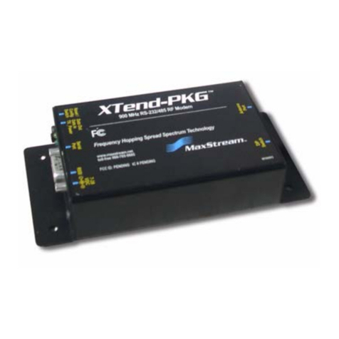
Digi XBee-PRO 900HP User manual

XBee-PRO 900HP
RF Modem
User Guide

Revision history—90002200
Revision Date Description
A December,
2013
Baseline release.
B May, 2016 Updated to include new Customer Support information. Corrected the
USB connector pin assignments and implementation table.
C May 2018 Added explanation of range estimates.
Trademarks and copyright
Digi, Digi International, and the Digi logo are trademarks or registered trademarks in the United States
and other countries worldwide. All other trademarks mentioned in this document are the property of
their respective owners.
© 2021 Digi International Inc. All rights reserved.
Disclaimers
Information in this document is subject to change without notice and does not represent a
commitment on the part of Digi International. Digi provides this document “as is,” without warranty of
any kind, expressed or implied, including, but not limited to, the implied warranties of fitness or
merchantability for a particular purpose. Digi may make improvements and/or changes in this manual
or in the product(s) and/or the program(s) described in this manual at any time.
Warranty
To view product warranty information, go to the following website:
www.digi.com/howtobuy/terms
Customer support
Gather support information: Before contacting Digi technical support for help, gather the following
information:
Product name and model
Product serial number (s)
Firmware version
Operating system/browser (if applicable)
Logs (from time of reported issue)
Trace (if possible)
Description of issue
Steps to reproduce
Contact Digi technical support: Digi offers multiple technical support plans and service packages.
Contact us at +1 952.912.3444 or visit us at www.digi.com/support.
XBee-PRO 900HP RF Modem User Guide 2

Contents
XBee-PRO 900HP RF Modem User Guide
Features 5
Worldwide acceptance 6
Specifications 6
External interface 7
RF Modem symbols 14
Interfacing protocols
RS-232 pin signals 17
RS-232 wiring diagram 17
DCE RF Modem to a DCE RS-232 device 18
Sample wireless connection: DTE <--> DCE DCE <--> DCE 19
RS-485 (2-wire) operation 19
RS-485 pin signals 19
RS-485 wiring diagram 20
RS-485 (4-wire) operation and RS-422 operation 20
RS-485 pin signals 21
RS-485 wiring diagrams 22
RS-485/422 connection guidelines 22
USB operation 23
USB pin signals 23
Agency certifications
FCC (United States) certification 26
Labeling requirements 26
FCC notices 26
Limited modular approval 27
FCC-approved antennas 27
Fixed base station and mobile applications 27
Portable applications and SAR testing 27
RF exposure 27
IC (Industry Canada) certification 27
Labeling requirements 28
Antenna options: 900 MHz antenna listings 28
Transmitters with detachable antennas 32
Detachable antenna 33
XBee-PRO 900HP RF Modem User Guide 4

XBee-PRO 900HP RF Modem User Guide
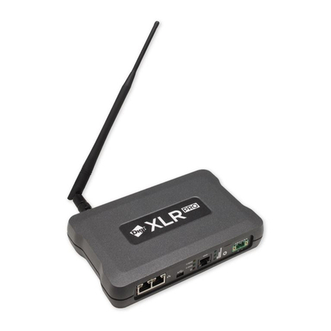
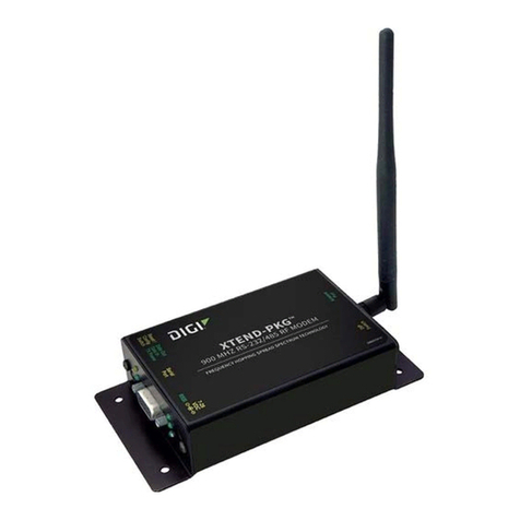
The XBee-PRO 900HP RF Modem is a small, low-power solution that uses the XBee-PRO 900HP 900
MHz RF Module in an enclosure to communicate with systems using RS-232, RS-485, and USB
interfaces. It allows you to easily make your existing wired systems wireless simply by connecting to
this product.
When a system is connected to the XBee-PRO 900HP RF Modem, it can transmit and receive data from
multiple radios on the same wireless network. This is achieved by using Digi’s XBee-PRO 900HP RF
Module.
This manual is not a comprehensive manual that provides a full description of the 900HP RF Modem.
This manual only covers the interfaces needed to communicate with the XBee-PRO 900HP RF Modem.
For an extensive guide on use of the 900HP 900 MHz RF Module, see the XBee-PRO 900 HP/XBee-PRO
XSC RF Modules User Guide.
Features
The following table highlights the key features of the XBee-PRO 900HP RF Modem:
Long range data integrity Low power
Range
Indoor/Urban: 200kbps: Up to 1000' (305 m),
10kbps: Up to 2000' (610m)
Outdoor line-of-sight: 200kbps: Up to 4 miles
(6.5km), 10kbps: Up to 9 miles (15.5km)
Transmit power: Up to 24 dBm (250 mW) (software
selectable)
Receiver sensitivity: -101 dBm (200kbps), -110 dBm
(10kbps)
RF data rate: 200kbps, 10kbps
Receive current: 60 mA (@9V)
Transmit current: 140 mA (@9V)
Advanced networking and security Easy to use
XBee-PRO 900HP RF Modem User Guide 5

XBee-PRO 900HP RF Modem User Guide Worldwide acceptance
XBee-PRO 900HP RF Modem User Guide 6
True peer-to-peer (no “master” required)
communications.
Mesh, point-to-point and point-to-multipoint
topologies supported.
Retries and acknowledgments.
8 hopping channels, each with over 65,000
available network addresses.
FHSS (Frequency Hopping Spread Spectrum).
No configuration required for out-of-the-box
RF data communications
Free XCTU software (Testing and configuration
software)
RS-232 and RS-485 variants configurable via
the mini USB port
Advanced configurations available through
standard AT and binary commands
Built in RS-232/RS-485/USB interfacing
Small form factor
Software-selectable serial interface baud rates
Support for multiple data formats (parity, start
and stop bits, etc.)
Free and unlimited Technical Support
Worldwide acceptance
FCC Approved (U.S.A). See Agency certifications for FCC requirements.
Systems that include XBee®/XBee-PRO® 900HP RF modems inherit Digi Certifications.
ISM (Industrial, Scientific and Medical) 900 GHz frequency band
Manufactured under ISO 9001:2000 registered standards
XBee®/XBee-PRO® 900HP (900 MHz) RF Modems are approved for use in the U.S, Canada, and
Australia.
Specifications
Note Range figure estimates are based on free-air terrain with limited sources of interference. Actual
range will vary based on transmitting power, orientation of transmitter and receiver, height of
transmitting antenna, height of receiving antenna, weather conditions, interference sources in the
area, and terrain between receiver and transmitter, including indoor and outdoor structures such as
walls, trees, buildings, hills, and mountains.
The following table highlights the specifications of the XBee-PRO 900HP RF Modem.
Specification XBee-PRO
Performance
Indoor/Urban Range 200 kb/s: Up to 1000 ft (305 m)10 kb/s: Up to 2000 ft (610m)
Outdoor line-of-sight Range 200 kb/s: Up to 4 miles (6.5 km) w/ 2.1 dB dipole antenna
10 kb/s: Up to 9 miles (15.5 km) w/ 2.1 dB dipole antenna
Transmit power output Up to 24 dBm (250 mW) software selectable
RF Data Rate (High) 200 kb/s
RF Data Rate (Low) 10 kb/s
Interface data rate 9600-230400 kb/s (Software selectable, includes non-
standard baud rates)
XBee-PRO 900HP RF Modem User Guide External interface
XBee-PRO 900HP RF Modem User Guide 7
Specification XBee-PRO
Receiver sensitivity -101 dBm (200 kb/s), -110 dBm (10 kb/s)
Networking and security
Frequency 902-928MHz (located in the 900 MHz ISM Band)
Spread spectrum Frequency hopping
Supported network topologies Mesh, point-to-point, point-to-multipoint, peer-to-peer
Antenna
Connector RPSMA (reverse polarity SMA)
Impedance 50 ohms unbalanced
Power requirements
Power supply 7-30 VDC
Receive current 60 mA (@9V)
Transmit current 140 mA (@9V)
Physical properties
Size 4.500” x 2.750” x 1.125” (11.4cm x 7.0cm x 2.9cm)
Weight 5.25 oz. (150 g)
Data connection Female DB-9, RS-485/422 screw terminal, USB Type B, USB
Mini-B
Operating temperature -40 - 85º C (Industrial)
Certifications (partial list) See Agency certifications for region-specific certification requirements.
United States (FCC Part 15.247) MCQ-XB900HP
Industry Canada (IC) 1846A-XB900HP
Australia RCM
RoHS Compliant
External interface
Front view of the RS-232 interface Description

XBee-PRO 900HP RF Modem User Guide External interface
XBee-PRO 900HP RF Modem User Guide 8
1-01a. RS-232 Serial Port
Standard female DB-9
1-01b. RS-232 Power Connector
7-30 VDC power connector
1-01c. RS-232 Reset Button
The reset button resets (re-boots) the
XBee-PRO 900HP RF Modem. This button
only applies when using the
configuration tabs of Digi’s XCTU
Software.
Front view of the RS-485 interface Description
1-03a. RS-485 Serial Port
Phoenix 6-pin connector.
1-03b. RS-485 Power Connector
7-30 VDC power connector.
1-03c. RS-485 DIP Switch
120 ohms termination for the receiving
differential pairs if switch is in the up
position. Switch 1 is for half duplex (2
wire) termination. Switch 2 is for full
duplex (4 wire) termination.
1-03d. RS-485 Reset Button
The reset button resets (re-boots) the
XBee-PRO 900HP RF Modem. This button
only applies when using the configuration
tabs of Digi’s XCTU Software.
Back view of the RS-485 interface Description

XBee-PRO 900HP RF Modem User Guide External interface
XBee-PRO 900HP RF Modem User Guide 9
1-04a. RS-485 RSSI LEDs
RSSI LEDs indicate the amount of fade
margin present in an active wireless link.
Fade margin is defined as the difference
between the incoming signal strength
and the modem's receiver sensitivity.
3 LEDs ON = Very Strong Signal (> 30
dB fade margin)
2 LEDs ON = Strong Signal (>20 dB
fade margin)
1 LED ON = Moderate Signal (>10 dB
fade margin)
0 LED ON = Weak Signal (<10 dB fade
margin)
1-04b. RS-485 I/O and Power LEDs
LEDs indicate RF modem activity as
follows:
Yellow (top LED) = Serial Data Out (to
host)
Green (middle) = Serial Data In (from
host)
Red (bottom) = Power/TX Indicator
(the red light is on when powered, off
briefly during RF transmission)
1-04c. RS-485 Commissioning Push Button
The commissioning push button
provides a variety of simple functions to
aid in deploying devices in a network.
See “Commissioning Push-button” in the
XBee-PRO 900HP/XBee-PRO XSC RF
Modules Product Manual for more detail.
1-04d. RS-485 USB Mini-B Port
When the USB Mini-B is plugged in, all
RS-485 communications to and from the
XBee are disabled. The USB is to serve as
a configuration port. The XBee should
not transmit if USB is plugged in.
1-04e. RS-485 Antenna Port
The antenna port is a 50ΩRF signal
connector for connecting to an external
antenna. The connector type is RPSMA
(Reverse Polarity SMA) female. The
connector has threads on the outside of
a barrel and a male center conductor.

XBee-PRO 900HP RF Modem User Guide External interface
XBee-PRO 900HP RF Modem User Guide 10
Back view of the RS-232 interface Description

XBee-PRO 900HP RF Modem User Guide External interface
XBee-PRO 900HP RF Modem User Guide 11
1-02a. RS-232 RSSI LEDs

XBee-PRO 900HP RF Modem User Guide External interface
XBee-PRO 900HP RF Modem User Guide 12
RSSI LEDs indicate the amount of fade
margin present in an active wireless
link. Fade margin is defined as the
difference between the incoming
signal strength and the modem's
receiver sensitivity.
3 LEDs ON = Very Strong Signal (>
30 dB fade margin)
2 LEDs ON = Strong Signal (>20 dB
fade margin)
1 LED ON = Moderate Signal (>10
dB fade margin)
0 LED ON = Weak Signal (<10 dB
fade margin)
1-02b. RS-232 I/O and Power LEDs
LEDs indicate RF modem activity as
follows:
Yellow (top LED) = Serial Data Out (to
host)
Green (middle) = Serial Data In (from
host)
Red (bottom) = Power/TX Indicator
(the red light is on when powered, off
briefly during RF transmission)
1-02c. RS-232 Commissioning Push Button
The commissioning push button
provides a variety of simple functions
to aid in deploying devices in a
network. See “Commissioning Push-
button” in the XBee-PRO 900HP/XBee-
PRO XSC RF Modules Product Manual
for more detail.
1-02d. RS-232 USB Mini-B Port
When the USB Mini-B is plugged in, all
RS-232 communications to and from
the XBee are disabled. The USB is to
serve as a configuration port. The
XBee should not transmit when the
USB is plugged in.
1-02e. RS-232 Antenna Port

XBee-PRO 900HP RF Modem User Guide External interface
XBee-PRO 900HP RF Modem User Guide 13
The antenna port is a 50ΩRF signal
connector for connecting to an
external antenna. The connector type
is RPSMA (Reverse Polarity SMA)
female. The connector has threads on
the outside of a barrel and a male
center conductor.
Front view of the USB interface Description
1-05a. USB Port
Type B USB port.
1-05b. USB Power Connector
7-30 VDC power connector.
1-05c. USB Reset Button
The reset button resets (re-boots) the
XBee-PRO 900HP RF Modem. This button
only applies when using the
configuration tabs of Digi’s XCTU
Software.
Back view of the USB interface Description

XBee-PRO 900HP RF Modem User Guide RF Modem symbols
XBee-PRO 900HP RF Modem User Guide 14
1-06a. USB RSSI LEDs
RSSI LEDs indicate the amount of fade
margin present in an active wireless link.
Fade margin is defined as the difference
between the incoming signal strength
and the modem's receiver sensitivity.
3 LEDs ON = Very Strong Signal (> 30 dB
fade margin)
2 LEDs ON = Strong Signal (>20 dB fade
margin)
1 LED ON = Moderate Signal (>10 dB
fade margin)
0 LED ON = Weak Signal (<10 dB fade
margin)
1-06b. USB I/O and Power LEDs
LEDs indicate RF modem activity as
follows:
Yellow (top LED) = Serial Data Out (to
host)
Green (middle) = Serial Data In (from
host)
Red (bottom) = Power/TX Indicator (the
red light is on when powered, off briefly
during RF transmission)
1-06c. USB Commissioning Push Button
The commissioning push button
provides a variety of simple functions to
aid in deploying devices in a network.
See “Commissioning Push-button” in
the XBee-PRO 900HP/XBee-PRO XSC RF
Modules Product Manual for more
detail.
1-06d. USB Antenna Port
The antenna port is a 50ΩRF signal
connector for connecting to an external
antenna. The connector type is RPSMA
(Reverse Polarity SMA) female. The
connector has threads on the outside of
a barrel and a male center conductor.
RF Modem symbols
The following symbols are found on top of the RF Modem. The description of the symbol is next to the
symbol.

XBee-PRO 900HP RF Modem User Guide RF Modem symbols
XBee-PRO 900HP RF Modem User Guide 15

Interfacing protocols
The XBee-PRO 900HP RF Modem supports the following interfacing protocols:
nRS-232
nRS-485 (2-wire) half-duplex
nRS-485 (4-wire) and RS-422
nUSB
RS-232 pin signals 17
RS-232 wiring diagram 17
DCE RF Modem to a DCE RS-232 device 18
Sample wireless connection: DTE <--> DCE DCE <--> DCE 19
RS-485 (2-wire) operation 19
RS-485 pin signals 19
RS-485 wiring diagram 20
RS-485 (4-wire) operation and RS-422 operation 20
RS-485 pin signals 21
RS-485 wiring diagrams 22
RS-485/422 connection guidelines 22
USB operation 23
USB pin signals 23
XBee-PRO 900HP RF Modem User Guide 16

Interfacing protocols RS-232 pin signals
XBee-PRO 900HP RF Modem User Guide 17
RS-232 pin signals
The following figure shows the pins used on the female RS-232 (DB-9) serial connector:
The following table describes the RS-232 pin assignments and implementation:
DB-9
pin
RS-232
Name Description Implementation
1 DCD Data-Carrier-
Detect
Connected to DSR (pin 6)
2 RXD Received Data Serial data exiting the RF modem (from host)
3 TXD Transmitted Data Serial data entering into the RF modem (from host)
4 DTR Data-Terminal-
Ready
2 – 0xFFFF [x 100 msec]
5 GND Ground Signal 0x20 – 0x7F
6 DSR Data-Set-Ready 0 - 4
7 RTS /
CMD
Request-to-
Send/Command
Mode
RTS (request-to-send) flow control: By default, this pin is not
used. To configure this pin to regulate the flow of serial data
exiting the modem, refer to the Serial Communications and RT
command section.
CMD: Refer to Binary Commands and RT Command Sections to
enable binary command programming.
8CTS Clear-to-Send CTS (clear-to-send) flow control –When pin is driven low, UART
host is permitted to send serial data to the modem. Refer to
the Serial Communications and CS Command sections for
more information.
9 RI Ring Indicator Optional power input (protection circuitry to prevent back flow
from other power sources internal to the board)
RS-232 wiring diagram
The following figure shows the RS-232 Device DTE Device (male DB-9 connector) wired to a DCE RF
modem (female DB-9) XBee-PRO RF Modem:

Interfacing protocols DCE RF Modem to a DCE RS-232 device
XBee-PRO 900HP RF Modem User Guide 18
DCE RF Modem to a DCE RS-232 device
The following figure shows the DCE RF Modem (female DB-9 connector) wired to an RS-232 DCE device
(male DB-9) XBee-PRO RF Modem:

Interfacing protocols Sample wireless connection: DTE <--> DCE DCE <--> DCE
XBee-PRO 900HP RF Modem User Guide 19
Sample wireless connection: DTE <--> DCE DCE <--> DCE
The following figure shows a typical wireless link between DTE and DCE devices:
RS-485 (2-wire) operation
Note that with the RS-485 variant of the XBee-PRO 900HP RF Modem, the RF Modem is defaulted with
the D7 command (AT parameter) to 7. This parameter controls the TX enable signal and allows the
modem to output any data in the DO buffer to the host device for the RS-485 interface. In the event
that the parameter is accidentally changed, which would halt RS-485 communication, a USB mini
cable should be plugged into the modem to reconfigure it. You can reconfigure by using XCTU.
With the USB plugged in:
1. Open XCTU and select the Com port of the USB.
2. Select the Terminal tab and type '+++'. The system will respond with 'OK'.
3. Type “ATD77” then <Enter>, and the system will respond with 'OK'. Type “ATWR” then <Enter>,
and the system will respond with “OK”.
4. Type “ATCN” then <Enter> to exit command mode, and the system will respond with “OK”.
5. Unplug the USB and return to the existing RS-485 interface. The 900HP RF Modem is now ready
to communicate in RS-485 model.
Note Failure to enter AT Command Mode is most commonly due to baud rate mismatch. Ensure the
“Baud" setting on the “PC Settings” tab matches the BD (Interface Data Rate) setting of the RF modem
(by default, BD parameter = 3, which is associated with 9600 baud).
RS-485 pin signals
The following figure shows the pins used on the RS-485 (2 wire) Phoenix 6-pin connector:

Interfacing protocols RS-485 wiring diagram
XBee-PRO 900HP RF Modem User Guide 20
Phoenix
6 pin
RS-485
name Description Implementation
1 TX/RX+ Negative
Data Line
Transmit serial data to and from the RF modem
2 TX/RX- Positive Data
Line
Transmit serial to and from the RF modem
5 GND Ground
Signal
Ground
6 PWR Power Signal Optional power input (protection circuitry to prevent back
flow from other power sources internal to the board)
3, 4 Not Used
RS-485 wiring diagram
The following figure shows the RF Modem in an RS-485 (2 wire) half duplex:
RS-485 (4-wire) operation and RS-422 operation
Note that with the RS-485 variant of the XBee-PRO 900HP RF Modem, the RF Modem is defaulted with
the D7 command (AT parameter) to 7. This parameter controls the TX enable signal and allows the
modem to output any data in the DO buffer to the host device for the RS-485/422 interface. In the
event that the parameter is accidentally changed, which would halt RS-485 communication, a USB
mini cable should be plugged into the modem to reconfigure it. You can reconfigure by using Digi's
XCTU.
With the USB plugged in:
1. Open XCTU and select the Com port of the USB.
2. Select the Terminal tab and type “+++”. The system will respond with “OK”.
3. Type “ATD77” then <Enter>, and the system will respond with “OK”.
Other manuals for XBee-PRO 900HP
1
Table of contents
Other Digi Modem manuals

Digi
Digi XBee 3 Cellular LTE-M User manual

Digi
Digi XBee Cellular 3G Global User manual

Digi
Digi XB3-C-G1-UT-001 User manual

Digi
Digi XLR PRO User manual

Digi
Digi XLR PRO User manual

Digi
Digi XStream-PKG-E User manual

Digi
Digi Rapidport User manual

Digi
Digi XBee-PRO XM-M92-2P Series User manual

Digi
Digi XBEE2 User manual

Digi
Digi TransPort WR11 User manual

Digi
Digi XTend-PKG User manual

Digi
Digi E230 User manual

Digi
Digi 9XTend-PKG-U User manual

Digi
Digi WAN 3G User manual

Digi
Digi Digi XBee SX User manual

Digi
Digi Connect WAN 3G IA User manual

Digi
Digi XB3-C-A2-UT series User manual

Digi
Digi XStream-PKG User guide

Digi
Digi XTP9B-PKC-UA User manual

Digi
Digi XStream-PKG-U User manual