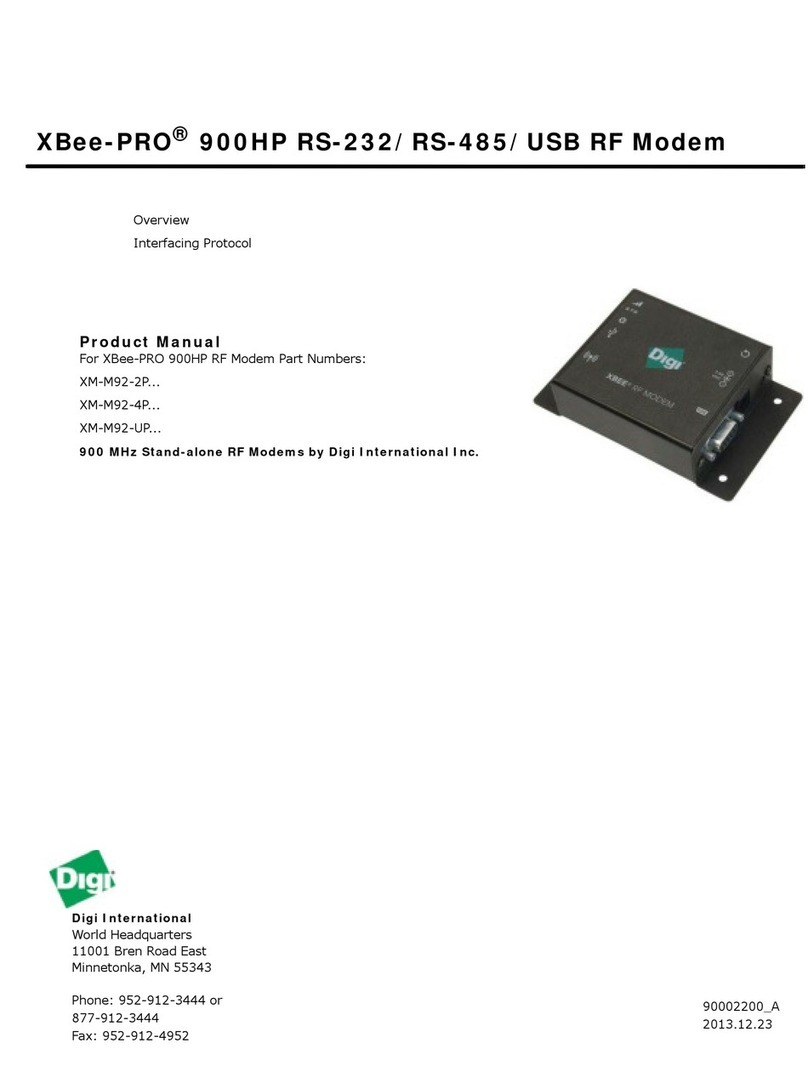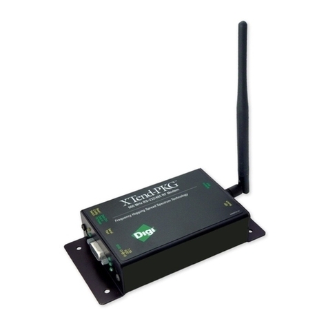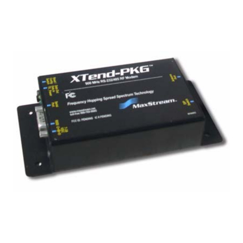
XStream-PKG-R™ RS-232/485 RF Modem – Product Manual v5.x00
1. XStream RS-232/485 RF Modem
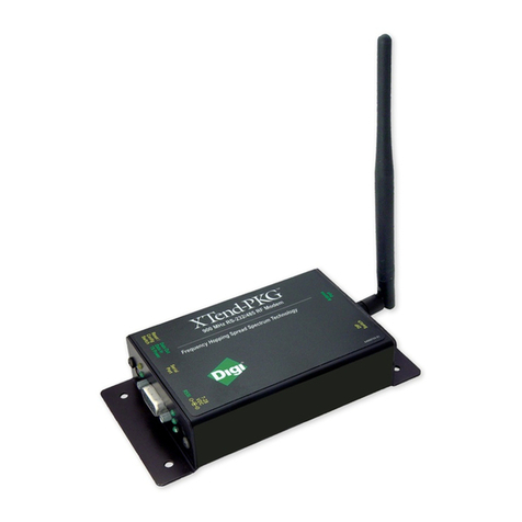
The XStr eam -PKG-R RF Modem prov ides long r ange data
com m unicat ions and advanced net work ing for OEMs and syst em
int egr ators. Out-of -box, t he m odem is equipped t o sust ain long range
wir eless link s betw een dev ices. Sim ply ent er serial data int o one
m odem and t he dat a surfaces on t he ot her end of t he wireless link.
The m odem t ransfers a st andar d asy nchr onous ser ial dat a st ream
bet ween t wo or m or e m od em s. I t s b uilt -in RS-232/ 485/ 422 inter facing facilitat es rapid
int egr at ion int o ex ist ing dat a syst em s.
1 .1 . Fe at u re s
Lon g Ran g e
9XStr eam -PKG- R ( 9 00 MHz) Range:
•I ndoor/ Urban: up to 1 5 0 0 ’ ( 450 m )
•Out door line-of-sight: u p t o 7 m ile s ( 11 k m )
w/ 2.1 dBm dipole ant enna
•Out door line-of-sight: u p t o 2 0 m ile s ( 3 2 k m )
w/ high gain ant enna
24XSt ream -PKG- R ( 2.4 GHz) Range:
•I ndoor/ Urban: up t o 60 0 ’ (180 m )
•Out door line-of-sight: u p t o 3 m iles ( 5 k m )
w/ 2.1 dBm dipole ant enna
•Out door line-of-sight: u p t o 1 0 m iles ( 1 6 k m )
w/ high gain ant enna
Receiver Sensitiv ity: -1 1 0 dBm ( 90 0 MHz) ,
-1 0 5 dBm ( 2. 4 GHz)
Ad va n ce d N e t w ork in g an d Se cu r it y
True peer-t o-p eer ( no “ m ast er ” r eq uir ed ) ,
point -t o-point , point-t o-m ultipoint , m ult idr op
Ret ries and Ack nowledgem ent s
7 hopping channels, each with over 65 ,000
available net work addresses
FHSS ( Fr equen cy Hop ping Sp read Spect r um )
1 .1 .1 . W or ld w ide Accept an ce
FCC Cer t ifie d ( USA) - Refer to Appendix A for FCC Requirem ent s.
Sy st em s t hat cont ain XSt r eam RF Modem s aut om at ically inherit Digi Cer t ifications.
I SM (I ndustrial, Scientific and Medical) frequency band
Manufact ured under I SO 9 0 0 1 :2 0 0 0 regist er e d st a n da rds
9XStream (900 MHz) RF Modem s are appr ov ed for use in US, Ca n a da , Au st r alia and I sr a e l
( an d m or e) .
Ea sy-t o-Use
Out -of-Box RF Com m unications -
no configuration required
Ex ter nal DI P Swit ch for configur ing:
•RS-232/ 485/ 422 support
( m u lt idr op in cluded )
•2- w ir e ( h alf -duplex) or 4-w ir e
RS-485/ 42 2 operat ion
•Par ity options
7- 18 VDC pow er supply
Sim ple AT and Binar y com m ands for
program m ing t he m odem
Soft w ar e-select able ser ial
int er facing rates
MODBUS, CTS, RTS, DTR, DCD
(and m ore) I / O Support
XI I ™ I nterference Blocking
Power -saving Sleep Modes
( as low as 6 m A)
© 2014 Digi International Inc. 4
