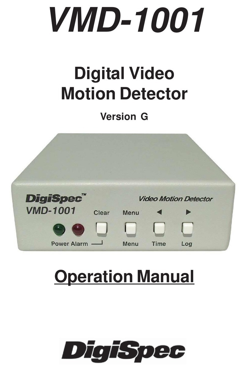
DigiSpec DS1-PL User manual

1
DS1-PL
July 2011
DIGITALOUTDOOR
VIDEO MOTION DETECTOR
TM
Version 6.17
OPERATION MANUAL

2
CONTENTS
Introduction ........................................................................................................................... 4
Features ................................................................................................................................ 5
5 Different Operation Modes ..................................................................................... 6
Motion Detection Parameter ..................................................................................... 6
Viewing Modes .......................................................................................................... 6
Motion Detection Set Up ............................................................................................ 6
Specifications ........................................................................................................................ 7
Detection Parameter ................................................................................................. 7
Zone Pattern Grid ...................................................................................................... 7
Alarm Outputs ........................................................................................................... 7
Connecting the Video ........................................................................................................... 8
Type of Cameras ....................................................................................................... 8
Cable ......................................................................................................................... 8
Lighting & Environment ............................................................................................. 8
Day / Night ................................................................................................................. 8
Florescent Lighting .................................................................................................... 9
Video Input / Output ................................................................................................... 9
Connecting the Alarms ........................................................................................................... 9
Alarm Output .............................................................................................................. 9
Alarm Connector DB-15 .............................................................................................. 10
Day / Night Inputs ...................................................................................................... 10
RS-232 ....................................................................................................................... 10
Connecting the Power ........................................................................................................... 10
Operation .............................................................................................................................. 11
Button Operation ....................................................................................................... 12
Normal Running Mode Button Functions ................................................................... 12
Programming Mode Button Functions ....................................................................... 13
Day / Night Mode ....................................................................................................... 13
Log Mode .................................................................................................................. 13
On-Screen Display during Running Operation ....................................................................... 14
Video Loss ................................................................................................................. 15
Programming the DS1-PL ...................................................................................................... 15
1. Motion Detection Menu .......................................................................................... 16
The Mode Setting .......................................................................................... 16
The Three Motion Detection Criteria ............................................................. 16
The Trigger Level .......................................................................................... 18
The Sensitivity Setting ................................................................................... 19
The Tracking Time Setting ................................................................................ 19
2. Zone Pattern Mask Menu ............................................................................... 19
The Cursor ..................................................................................................... 20
Button Function ................................................................................................. 20
3. Alarms, Relays, Menu .................................................................................... 21
Buzzer Setting ............................................................................................... 22
Relay Output Setting ..................................................................................... 22
External Input Setting ................................................................................... 23
Watchdog Timer ........................................................................................... 24
Entrance Delay Setting .................................................................................. 24
Exit Delay Setting .......................................................................................... 24
Alarm Process ................................................................................................ 24
Alarm Output Time Setting ............................................................................ 24
Alarm Reset Time Setting ................................................................................. 25

3
CONTENTS
4. Timers Menu .......................................................................................................... 25
The 3 On-Off Timer Settings .......................................................................... 25
Start and Stop Times .................................................................................... 26
Timer Examples ............................................................................................ 26
The Day/Night Timer Setting ......................................................................... 28
5. On-Screen Data Menu ........................................................................................... 29
The Layout Setting ....................................................................................... 29
The Position Settings .................................................................................... 29
The Status Settings ....................................................................................... 30
The Calendar Display Setting ....................................................................... 30
The Time Display Setting .............................................................................. 31
The Trace Effect Setting ................................................................................ 31
The Video Blackout Setting ........................................................................... 33
The Titler Display Setting .............................................................................. 33
6. Camera Titler Menu ............................................................................................... 33
The Titler Settings ......................................................................................... 34
7. Date-Time Menu .................................................................................................... 34
The Date Time Settings ................................................................................. 34
Clearing The Alarm Counter ......................................................................... 34
8. Serial Port Menu ......................................................................................................... 35
The Mode Setting .......................................................................................... 35
The Address Setting ...................................................................................... 36
The Output Rate Setting ............................................................................... 36
The Output Data Setting ................................................................................ 36
The Text Output Mode Setting.................................................................................37
TCP/IP .......................................................................................................... 38
Serial Input Alarm Setting..................................................................................... 38
9. Video Loss ............................................................................................................ 39
Video Loss Alarm .......................................................................................... 39
Video Loss Buzzer ........................................................................................ 39
Video Loss Alarm Output .............................................................................. 39
10. Master Reset ........................................................................................................ 40
APPENDIX A .......................................................................................................................... 41
DS1-PL Feature / Alarm Connector ............................................................................ 41
DS1-SPL Feature / Alarm Connector ......................................................................... 41
APPENDIX B ........................................................................................................................... 42
Ethernet LAN Adpater ................................................................................................ 42
LAN and DS1-PL Connection ...................................................................................... 42
APPENDIX C - Cable Pinouts .................................................................................................. 42
APPENDIX D - DSVMD Software ............................................................................................. 43
Installation ................................................................................................................. 43
Opening Window ....................................................................................................... 43
Serial Connection ...................................................................................................... 43
Ethernet Connection .................................................................................................. 44
Setup IP Address ....................................................................................................... 44
Communications Complete ....................................................................................... 45
Main Menu ................................................................................................................ 45
APPENDIX E - Serial Protocol Rev 10 .................................................................................... 46
APPENDIX F - PC to DS1-PL Connection Pin Out .................................................................. 52
APPENDIX G - DS1-PL Relay Adapter .................................................................. 53
Limited Warranty ......................................................................................................................... 55
NOTES ........................................................................................................................................ 56
LISTOFTABLE
Table 1 : DB-15 Pin-Out ................................................................................................................. 10
Table 2 : DB-15 Female Connector .......................................................................................... 41
Table 3 : LAN Adapter or PC to DS1-PL PinOut ....................................................................... 42

4
INTRODUCTION
Congratulationson your purchaseof the DigiSpecDS1-PLDigital VideoMotion Detector. Youare now theowner of one
ofthemostinnovative, precise and reliablemotiondetectorsavailable today. DigiSpec wouldliketopersonally thank you
for your purchase and would like to provide you with additional information on this remarkable product. The DS1-PL
utilizesanewtechnologydevelopedbyDigiSpeccalledQuantivision.Thisdevelopmentdividesthevideoimageintoover
262,144 pixels and analyses it 30 times per second for NTSC and 25 times per second for PAL. This insures instanta-
neous motion detection on a real time basis. By utilizing pipeline processing, DS1-PL handles millions of calculations
per second, which greatly decreases the decision time and increases reliability.
Traditionally, motion detection has been used for surveillance and security applications. Special features such as the
Black-Out, Trace, and Museum Modes as well as the Delta Effect allow security personnel to quickly ascertain and
respond to suspect motion. These features and many more are just small examples of the innovation built into this
product. This unit is perfect for indoor or outdoor, low light and difficult applications. Regardless of the job, the DS1-PL
can handle it.
The flexibility of this unit has been proven in a variety of environments. Machine vision systems have been developed
withintheindustrialmarketplace. The DS1-PL hasalsobeenutilized to assist in groundbreakingresearchin the Medical
arena. The extreme sensitivity of this product allows very precise analysis of any video image in airport ques and
immigration.Byutilizingtheunit’sRS-232portand/orLANadpatersandapersonalcomputer,motioncanbestudiedand
plotted over time or output to a paper chart recorder to facilitate motion signature analysis. The limit of the DS1-PL is
limited only to the creativity of the user.
Regardlessofyour application the DS1-PLwillopen up numerous possibilitiesforyou. This ground breakingtechnology
isrepresentativeof our commitment to Quality, Value andInnovation in every product we manufacture. Weareand will
continueto beThe Leader inDigital VideoMotion Detection Technology.
ThankYou
DigiSpec Inc.
1906TrebleDr.Houston,Texas77338
Telephone28-540-6665 Fax 281-540-6972
Email:[email protected]
WebSite:www.digispecvideomotion.com
WARNING!
TO PREVENT FIRE OR ELECTRIC SHOCK, DO NOT EXPOSE THIS APPLIANCE TO RAIN OR MOISTURE !
Table 4 : LAN Adpater to PC PinOut .............................................................................................. 42
Table 5 : LAN Adapter or PC to DS-16 ............................................................................................ 42
LISTOFFIGURES
Figure 1 : Video Input / Output ............................................................................................... 9
Figure 2 : DS1-PL BASIC CONFIGURATION ............................................................................ 11
Figure 3 : Button Operation ................................................................................................... 11
Figure 4 : Trace “Memory” .......................................................................................................... 32
Figure 5 : Trace “Memory Strobe” .............................................................................................. 32
Figure 6 : Blackout “On” & Trace “On” ....................................................................................... 32
Figure 7 : Blackout “Auto” ........................................................................................................... 32
Figure 8 : LAN and DS1-PL Connection ........................................................................................ 42
Figure 9 : Software Select Window .............................................................................................. 43
Figure 10 : Setting Window ........................................................................................................... 43
Figure 11 : DS1-PL to Laptop Serial Connection .........................................................................43
Figure 12 : Setting IP & Baud Rate Window ................................................................................. 44
Figure 13 : LAN Adpater to Laptop Connection ............................................................................... 44
Figure 14 : IP Address Setting Comport ........................................................................................ 44
Figure 15 : IP Address Setting ....................................................................................................... 44
Figure 16 : Main Menu DSVMD ...................................................................................................... 45
Figure 17 : PC to DS1-PL Connection Pin-Out .............................................................................. 52
Figure 18 : DS1-PL Relay Adapter ..................................................................................................................... 53
Figure 19 : DS1-PL Alarm Relay Board Schematic............................................................................................ 54

5
WARNING!
THISEQUIPMENTGENERATES , USESANDCANRADIARE RADIO FREQUENCYANDIFNOT INSTALLEDAND
USEDINACCORDANCEWITH THE INSTRUCTIONS MANUAL, MAYCAUSEINTERFERERCE TORADIOCOM-
MUNICATIONS IT HAS BEEN TESTED FOUND TOCOMPLY WITH THE LIMITED FORACLASS ACOMPUTING
DEVICE PURSUANT TO SUBPART JOF PART 15 FCC RULES, WHICHARE DESIGNED TO PROVID REASON-
ABLEPROTECTIONAGAINTSUCH INTERFERENCE WHEN OPERATED INACOMMMERCIALENVIROMENT.
OPERATION OF THIS EQUIPMENT INARESIDENTAREA IS LIKELY TO CAUSE INTERFERENCE IN WHICH
CASE THE USER AT HIS OWN EXOENSE WILL BE REQUIRED TO TAKE WHATEVER MEASURES MAY BE
REQUIREDTO CORRECTTHEINTERFERENCE
DS1-PL Features
PTZ Mode
Thismode allows theuse of Pan/Tilt/Zoom cameras whileoperating in theVMD mode. The unit electronicallymonitors
theentirevideo image and iftheentirescreen is moving simultaneouslythenthis is determined tobeaPTZ moving. The
VMD is disabled until the PTZ comes to rest and then enables the VMD function after a programmable period of time.
Tracking Modes
Thepopular“Trace”modesof the DS1-PL have beenenhancetoallowmotion tracking to be displayedandsavedonthe
screen. Unlike other units that have arrows or boxes we actually display the form outline of the motion tracking target,
so the user can easily identify friend or foe and travel direction.
TCP/IP LAN Compatibility
The DS1-PL and DS-16 Rack now can be easily added to networked systems via the new LAN adapter using UDP
protocol of standard ethernet LAN systems. This adds convenience and flexibility in large enterprise or proprietary
systems.
DSVMD Windows Software
NewandimprovedfeaturesofthepowerfulWindowsbasedprogrammingandcontrolsoftware.Fully compatible with our
TCP/IPLAN andinterface andincluded withat no additional charge.
Watchdog Timer Output
The DS1-Pl can be programmed to give a periodic signal output to inform other equipment the VMD is continuously
onlinevia this hardware signal. The DS1-PL always had a Watchdog timer input to monitor other equipment when
theyare operational via ourAlarm input function.
Video Loss Mode
This mode has added some programming features to make the video loss mode more flexible when interfacing with
otherequipment downthe line.
Alarm Process
The alarm modes have also been enhanced to allow for dwell or timed modes for ease in interfacing to other alarming
devices.
/ FCC / RoHS Compliant

6
Features
5 Different Operating Modes
MotionDetection - 1 to 8Zones for Perspective Detection
Motionless Detection - 1 to 8 Zones
Direction Detection - Up to 4 Directions
MuseumMode
PTZ-CompatibleMode
Motion Detection Parameters
TrackingTime- Velocity of Movement
Size - Number of Pixels that Change
Sensitivity-Amountof Contrast Changes
288ProgrammableAreasMaximumperZone
8IndependentlyProgrammableZones
Viewing Modes
Trace Mode - OutlinesMovingTargetsinmemory or strobemode
BlackoutMode
BlackoutandTrace Modes Combined
Motion Detection Set-Up
Total Pixel Count
Peak Pixel Count
AlarmCountby Zone
Analyzesvideo atthe pixellevel with262,144 detectionpoints
On-ScreenMenus
160-EntryEventLog
VideoLoss with Programmableaudible, red screenor alarm output
3Daily Timers forOn/Off and Weekend/HolidaySettings
NTSC/RS-170A,PAL/CCIR, and SECAM Compatible
Asynchronous;requires no externalcamerasynchronization
Buzzer Settings forAlarm and Proximity Detection
Date/Time generator withallInternationalStandards and Daylight Savings
NiMH Battery Backup for Date/Time when power is lost
InternalDay / Night Timer
Day / Night modes can be switched by external devices
8IndividualZoneAlarmOutputs
1 Global Form C alarm output - NC and NO with common
1AlarmInput(“AND/OR/Enable/Disable”Selectable)
Non-VolatileEEPROM Backup Memory
16-CharacterCameraTitling
RS-232 Programmingvia PC forall Functions andSetups
EthernetLANProgramming with optional adapter
SerialPrinter Port for printingEvent Log
WatchdogTimerInternal and Output
ProgrammableAlarmProcesseitherTime orRetrigger
PowerfulWindows-basedSoftwareforset-up and control
FirmwareUpdatebyRS-232 port using LaptopandHyperTerminal
DIGITAL VIDEO MOTION DETECTOR
Features

7
DIGITAL VIDEO MOTION DETECTOR
Alarm Input HiZ100K ohm 12VDC Max
Programming On-Screenwith Momentary Pushbuttonsfor selectionor RS-232 /LAN
Serial Communication RS-232Cwith openAPI commandset
StatusIndicators Power :Green LED (Solid Onwhen power applied)
Alarm Mode :Red LED (SolidOn when enabled, OFF whendisabled, and
Flashingwhenalarm active
Setup : Yellow LED
Day / Night :Green LED (On when daymode, OFF when night mode)
LOG :Yellow LED (On when LOG isbeing displayedon-screen)
Trace Gray Scale White to Gray Adjustable internal control
Backup Program Memory Non-VolatileEEPROM memory
T/D Backup 4days via SuperCapacitor (withoutpower connected)
Power 7-15VDC3.3W Max via2.1mmx5.5mm DC PowerJack
12VDC@190mANominal
12VDC@360mAwhenAlarmingandBuzzer sounding
Temperature 32F - 120F / 0C - 50C
Humdity 0-85%NonCondensing
Size 230mm(D)x130mm(W)x38mm(H)/9”(D)x51/8”(W)x1.5”(H)
Weight 1 lb / .46 Kg
Construction ComputerBeigeMetal Enclosure
Warranty 2 years, parts and labor
Specifications
Motion / Direction / Motionless / Museum / PTZ Modes Detection Parameters
Size Settings; 0 - 65,535 pixels
Sensitivity Settings; 0 – 100
Tracking Settings; 0 – 8 seconds, in 0.1 second increments
Zone Pattern Grid: 288 Zones (NTSC or PAL)
Video Input: 1 V P-P, 75 ohm terminated, NTSC, PAL,SECAM +/- 20%
VideoOutput: 1V P-P 75 ohmterminated orunterminated
VideoInput/ Output: BNC individualvideoloop-through outputs per channel
AlarmOutputs
Time:0-99seconds
8Individual Zone Outputs,opencollector transistor viaDB-15 (20ma Max.at 5VDC)
Watchdog Timer Output usesAlarm Output H when selected
Global Form C output, either N/O or N/C with common (1AMax at 12-24 VAC / VDC)
Specifications

8
Connecting the Video
Type of Cameras
Precautions
The DS1-PL functions best with high quality video cameras. Cameras must be securely locked down so the picture is
stable and jitter free. If the picture jitters or the DS1-PL character display jitters, the DS1-PL may false trigger. If the
camera has any sync or phase adjustments, try adjusting these first.
To select the right camera for your application (i.e. indoor, outdoor, low light, no light), you should consider the advan-
tagesand disadvantages of eachtype.
CCD
High quality CCD cameras will work well with the DS1-PL. The higher the resolution, the more precise the motion
detection.CCDcameras work equallywell in both indoorand outdoor environments.Itis recommended thatB&W CCD
camerasbeusing in outdoorapplicationsdue to their increasedresolution. B&W low lightlevelCCD cameras shouldbe
usedinlow light conditions.CCDcameras are sensitive toInfrared (IR) light andcanbe used fornightvision with the aid
ofanInfraredIlluminator.
IR
Infraredcamerasshouldbeusedfornolightapplicationsorverysensitivenightvisionapplications.IRcamerasarebetter
equippedfornight vision than CCDcameras.
Cable
Itisimportant that youusethe proper cabletypeand installation procedures wheninstalling the cameras andyourDS1-
PL. Make sure you use standard RG-59U coaxial cable with at least 95% braided shield for video transmission.
When installing, make sure that you do not run the cable near any power lines for they may cause interference in the
videotransmission.Ifyouarecablingbetweenfloorsorlongdistances,useconduit to protect the cable from interference.
Properprotection of thevideo cable fromexternal power interference, weather, andwater is importantto ensure aclear
transmissionof video signaland reliable motiondetection.
Groundingproblems between thevarious components of avideo system maycause noise orhum bars toappear in the
videoimage.Thismustbeeliminated by properly grounding all equipmenttoanearthgroundandmaking sure all shields
are intact in all video coaxial cables. Grounding problems will effect the reliability of motion detection.
Lighting & Enviromental Conditions
Unlessa camera isin a controlled environment, fluctuationsin conditions willoccur.The DS1-PLprovidesthe flexibility
to configure the Video Motion Detector for two separate sets of conditions.
Day/Night
TheDS1-PLworks in boththe day andnightenvironments. But, eachmayrequire different configurations.The DS1-PL
providestwosetsofsettingsthatcanbeprogrammedbytheuser. One group ofsettingscanbeusedforday settings and
theother for nightsettings or forwhatever other conditionsthe user wishesto set themfor. Night settingsrequire higher
sensitivity, lower trigger levels, and shortertracking times, makingthe DS1-PLmoresensitive to motion.TheDay/Night
mode may be toggled from day to night by giving a relay closure to ground on the Day/Night input – Pin 8 or using the
Day/Night timer to switch modes at a predetermined time.
Refer to Table 1 for more information.
Connecting
DIGITAL VIDEO MOTION DETECTOR

9
Connecting
DIGITAL VIDEO MOTION DETECTOR
Florescent Lighting
Gradualorsuddenlighting changes, video noise,intermittenceorglitches in video lines,orpowersurgescan be ignored
by the DS1-PL. To compensate for such occurrences a balance must be reached in the configuration of the motion
criteria(see Motion Criteria).Fluorescent light may resultin high speedflickering when aCCD camera isused. Various
camerashave shutter selectionsforflickerless option oryou may haveto disable theAutoWhitebalancefeature on DC
versions.Anothersolutionis to change the lightingballast to an electronic onethat operates at a higherfrequency than
the video sync signal.
Video Input / Output
Thevideoinputandoutputarelocatedontherearoftheunit.(seeFigure1).The video input connects to the video source
viatheleftBNCconnector.Thevideooutputconnectstoadisplay, recording device, switcher,orother equipment via the
rightBNC connector. Boththe inputand output are1 V P-Pinto75 ohms unbalancedEIAstandard RS-170A/ NTSCor
CCIR / PAL video format. Improper input termination or looping will cause the video level to be too low and effect the
motiondetection. Improper outputtermination will make theimage or thevideo recording poor.
Connecting theAlarms
Alarm Output
Theunit has oneForm-C alarm output withnormally open (N/O)and normally closedN/C configurations. Itwill produce
aclosure and openwhenever analarm occurs.An alarm occurswhen the DS1-PLdetects motion orthere isvideo loss
and the alarm has been enabled by pressing theALARM ON-OFF button (red LED on). The contacts remain closed or
openforthe duration programmed intheRelay Hold time. Iftheunitis set withaRelayHold time ofzero,noalarm will be
produced. The location of the alarm output connector is seen in Figure 1 and the pin-out configuration for the DB-15
connectorisseeninTable1. Analarmconnectoradapter is provided with theunit.AllsignalsoftheDB-15connectorcan
be connected to this adapter via the screw terminals.
Someequipment may requirea dry contact closure (normallyopen). Connect suchequipment to the N/O andcommon
leads. For a normally closed alarm, connect between the N/C and common leads. There is no polarity; so these leads
maybe swapped aroundorACvoltagesused. Other equipmentmay require aclosure to ground.In this case,a ground
connectionwillbeprovided on such equipment.Connectthe common lead togroundandthe N/O lead totheinput of the
equipment. There is no voltage on the alarm connectors of the DS1-PL. No damage can be done by incorrect wiring
exceptexceeding the currentor voltage rating.
Figure 1 : Video Input / Output

10
Connecting
Alarm Connector DB-15
TheDS1-PLhas afemale DB-15Alarmconnectorwith the followingpin out foradditional functions.
Pin # Function
1 AlarmAreaA
2 AlarmArea B
3 AlarmAreaC
4 AlarmAreaD
5 AlarmArea E
6 AlarmAreaF
7 AlarmAreaG
8 AlarmAreaH
9 N/C(NormallyClosed)UniversalAlarm
10 N/O(NormallyOpen)UniversalAlarm
11 Com(Common)UniversalAlarm
12 Ground
13 RS-232SerialOutput(TXD)
14 RS-232SerialInput(RXD)
15 External ContactInput
Shield Ground
Table 1 : DB-15 Pin Out
Note
Pins 9-11 are Form C relay contact
Pins1-8 are open collector transistoroutputs (normally open)
Pin 15 is HiZ 100K ohm Max 5VDC input forAlarm or Day/Night mode
Day/NightInputs
The Day/Night input switches settings from day settings to night when the unit receives a closure to ground on the
external contact input. If left open, day settings will be effective. An external timer, switch or photo cell can be used to
switch from day to night.
RS-232
The DS1-PL has an RS-232 interface for motion analysis and system configuration and operation that can be used in
conjunction with a PC or any RS-232C transmitting device. The DSVMD Windows based software gives complete
programming and operational command to the DS1-PL. The standard command set can be used to integrate control
functionswithinthe users proprietary systemfortotal system solution. SeetheSerial Protocol section onpage44 for the
complete command set.
Connecting the Power
The DS1-PL operates from a DC supply range from 7V to 15V DC. The power input connector, a standard 2.1mm x
5.5mmpowerjack, must havepositive(+) on thecenterand negative (-orground) on theoutershell. The unitisreverse
protected and correct polarity is indicated by the green Power LED being lit on the front panel.
Formobileoperationanegativegroundsystem is required. The unit maybeoperatedfromregularhouseholdpower with
theappropriateadapter.
DIGITAL VIDEO MOTION DETECTOR

11
DESCRIPTION
The DS1-PL is most commonly used for single channel systems requiring precision video motion detection. An alarm
outputcanbeusedtotripaneventor timelapserecorderintoreal-timerecording. Anexternaltimercanbeusedtotoggle
theDS1-PLbetweenDayandNightmodes.Sincetheunitis12VDC,itisperfectforcovertsurveillanceapplications.An
optional RS-232remotecommunicatingdevicecanbeusedforprogrammingandoperationremotely.
Operation
Fourbuttonsonthe front panelgivefull control of theunit.All settingsareguidedbyon-screen prompts.Simplypressthe
MENUbutton and followthe on-screen instructions.
The five LED’s indicate the state of the unit. The green Power LED indicates the unit is connected to the appropriate
powersource.TheredALARMLED indicates theunit is armedwhen solid and alarmed whenflashing.Theyellow LED
abovetheMENU button indicates theunit is in theset-upmode. The green LEDabove the D/N buttonislit when the unit
isintheday mode and offwheninthe night mode. The yellowLEDabovethe LOG button islitwhenthe unit is displaying
theLog Page on-screen.
DAY/NIGHT INPUT
DS-1
MONITOR
ALM OUT 1
VID OUT 1
CAMERA
TIME-LAPSE RECORDER
EVENT RECORDER
Figure 2 : DS1-PL BASIC CONFIGURATION
Operation
DIGITAL VIDEO MOTION DETECTOR
Figure 3 : Button Operation

12
Button Operation
The DS1-PL has 4 buttons, with associated LED’s, to provide all necessary functions.
Therearefourmodes of operation oftheDS1-PL
1)NormalRunningMode
2)ProgrammingMode
3)Day/NightMode
4)LogMode
1) Normal Running Mode Button Functions
Inthismode,theDS1-PLisprocessingalarms(if enabled) and displaying the date-time (ifenabled).Thebuttonfunctions
which are written below eachbutton,andare as follows
Alarm Button TheAlarmbutton toggles betweenalarm enabled or disabled. Whenthe alarm isenabled, the
DS1-PL will generate alarms whenever the motion detector qualifies valid motion. When the
alarm is disabled, all motion will be ignored. There are 2 indicators which display the alarm
enable/disablestatus.TheredLEDon theAlarm button willbe lit duringalarmenabled and will
be off during alarm disable. On-screen, theAlarm enabled status will display “A” if alarms are
enabled,and “a” ifalarms are disabled.
If an alarm is active (i.e. the DS1-PL is generating an alarm) the red LED will be flashing.
PressingtheAlarmbutton will clear thealarm. Every time theAlarmbutton is pressedthereaf-
ter,alarms will togglebetweenenabled/ disabled again.
Operation
Note
The3 On-Off timerswill override thefront panel alarmenable/disable toggle when their startor stop times
arereached. If you want tomanually control the enabling fromthe front panel, you shoulddisable all3 On-Off
timers, in the Timers Menu.
ProgramButton TheProgram button startsthe programming mode,which bringsup the MainMenu onscreen
with a blue back ground. The yellow LED will be lit while in this mode.
Day/NightButton TheDay/Nightbuttontogglesbetweendayandnightsettings.TheDS1-PL can be programmed
for two indepen dent settings, called Day and Night, but these do not necessarily mean pro-
gramming is required for Day and Night. It could be any time of the day or if there is any need
to switch between two programmed settings. There are 2 indicators which display the Day/
Night status. The green LED on the Day/Night button will be lit during Day settings and will be
off during night settings. On-screen, the Day/Night status will display “d” during day settings
and“n” during night settings.
DIGITAL VIDEO MOTION DETECTOR
Note
Theday/night timer will overridethe front panelday/nightbutton when Theday/night timer willoverridethe
frontpanelday/night button when theirstartor stop times arereached.If you want tomanuallycontrol the day/night
switching from the front panel, you should disable the day-night timer, in the Timers Menu.

13
Log Button The Log button displays the Log Page on-screen on a green background. This displays the
mostrecent160 alarm events,withtheir dates andtimes.Pressing the left/rightbuttonsscrolls
forwards of backwards through the log. Pressing the Menu button prints the complete log.
Pressing the Clear button reverts back to normal running operation. The yellow LED will be lit
above this button while in the Log Display mode.
2) Programming Mode Button Functions
n this mode the DS1-PL is being set up. The yellow LED on the Menu button will be lit, and the screen will have a blue
background(except for zonepattern settings). The button functionsare as follows:
ClearButton TheClearbuttonis used toleavemenuone level uporrevertback to normal runningoperation
ifcurrentpageismainmenupage.If any changes were made, theywillbesavedtonon-volatile
memoryand these changes will take immediate effect on theoperation ofthe DS1-PL.
Menu Button The Menu button steps through the programming options which are displayed on screen with
flashing prompts.Each time the menu button is pressed, the next prompt will flash indicating
that you may set this prompt.At the end of each menu page, the last prompt will wrap around
to the top of the page (the first prompt).
LeftButton The Left button is used to set the prompt by reducing its value if it is numeric, or sequencing
backwardsif it is a text prompt. During zone pattern settings, the cursor will move to the left.If
you hold the Left button pressed for longer than a second, many of the settings will automati-
cally change 3 times per second, or the zone pattern cursor will move left at a rate of 5 times
persecond.
RightButton TheRightbutton is usedtoset the promptbyincreasing its valueifit is numeric,orsequencing
forwards if it is a text prompt. During zone pattern settings, the cursor will move to the right. If
youhold the Rightbutton pressed for longerthan a second,many of thesettings will automati-
cally change 3 times per second, or the zone pattern cursor will move right at a rate of 5 times
persecond.
3) Day/Night Mode
TheDS1-PL has twosets of programmingsetups, one for Dayand one forNight. The GreenLED above theD/N button
when lit signifies the unit is in the Day mode. When the light is not lit the unit is in the Night mode.This light can be
controlled by the front panel button D/N, RS-232 command, or external input when selected as Day/Night input or the
internaltimer.
4) Log Mode
The Log mode is constantly enabled and every event is recorded into the Log memory. When the Log memory is full to
itsmaximum of160events,the oldest event isdiscardedand the newest eventreplacesit.ToentertheLog Mode, press
theLOGbutton on the frontpanel.The screen willhaveagreen background andthelatest logged events willbepresent
on the screen. Repeatedly press the LOG button to scroll through all the store logged events. Press the D/N button to
scroll the opposite direction through the Log File. To exit, press theAlarm button to return to normal operaton. The Log
modecan be entered by remote RS-232 operationalso. The Log memory can not beerased unless you do a complete
system Master Reset which will set all the programmed settings to the factory defaults.
Operation
DIGITAL VIDEO MOTION DETECTOR

14
On-Screen Display
On-Screen Display during Running Operation
Duringnormalrunning mode, various informationisoverlaidonto the videopicture.Thisis used as statusinformation,to
be recorded to tape, or viewed by the person watching the monitor.Any or all this information may be turned on or off.
Refer to the On-Screen Data programming screen.There are 2 layout formats, Stacked and Series. This is set so that
image information is not obscured by this overlaid on-screen data. Stacked creates a tall and narrow display format.
Series creates a short and wide display format. The position of this block of information can further be positioned
anywhereon the screenby adjusting thehorizontal and vertical position inthe On-Screen Dataprogramming screen.
Series Stacked
ABCDEFGHIJKLMNOPssssssss
MMM-DD-YY HH:MM:SSA A00d
Description
ABCDEFGH 16-charactercamera ID. Letters,numbers, and specialcharacters
IJKLMNOP split into 2 blocks of 8 characters each if stacked.
ssssssss Status display of up to 8 areas as defined in the zone pattern setup.Indicates areasA-H from
leftto right. Each of these8 status indicators displays informationpertaining the defined area,
and there are 5 symbols used to indicate the status
1) space Areais not enabled
2) . (dot) Area isenabled
3)-(dash) Areahas motion
4) a - h Areahas motion exceedingtrigger level(a-hforrespective area)Use thisas
an indicator to assist in adjusting trigger level.
5)A- H Areahas qualifiedalarm(A-Hfor respectivearea)Use this asanindicator to
assist in adjusting tracking time.
MMM-DD-YY Month(in 3 character alpha format, e.g. JAN,FEB,MAR...), Date, and Year. The sequence of
thesecan be changed at theCalendar mode prompt, in theOn-Screen Data set-up menu, for
USA,Canadian,European,or Japanese formats.
HH:MM:SSA Hours, Minutes, Seconds, and AM/PM flag. The format can be changed in the Time mode
prompt to display 12-hour mode (with AM/PM), or 24-hour mode (military time). Whichever
mode chosen will also be used in the Timer mode menu screen.
A00d Alarm Enable Status,Alarm Counter, Day/Night Status.
Alarm Enable status will display “A” (upper case) when alarming is enabled (the red LED will
alsobe lit), or “a” (lowercase) when alarmingis disabled(the red LEDwill also be off). During
analarm output condition,the status willchange to a“ * ” (asterisk) andat the endof the alarm
output it will revert back to “A”.
TheAlarmCounter countsupfrom 00 to99 every time analarm is generated. Thisishelpfulin
searching a tape for the start of alarm events. Manually clearing an alarm (by pressing the
Alarm button) resets this counter to 00.
The Day/Night status will display “d” during Day mode settings, and “n” during Night mode
settings.Thegreen LED ontheDay/Night button will alsobelit during Daymodeand will be off
forNightmode.
DIGITAL VIDEO MOTION DETECTOR
A00d
ssssssss
ABCDEFGH
IJKLMNOP
MMM-DD-YY
HH:MM:SSA

15
Programming
Video Loss
When video goes missing from the DS1-PL, a red warning background will be displayed with the message flashing
“VIDEOLOST”inlargecharacters.Ifthedate-timeinformationisenabled(seethe On-Screen Data programming menu),
thedateandtimewhenvideowentmissingwillbeinsertedunderthe“VIDEOLOST”message.Thiswillwarn an operator
of the video loss condition and give the time and date of this occurrence. If the video is recorded to tape, the date and
timewill provide when thevideo loss hadoccurred.
After video has been restored, the DS1-PLchecks its validity, then does a “cold boot” which restores the DS1-PLto its
condition prior to video loss. See Section 9., Video Loss for programmig options for this function.
Programming the DS1-PL
Tostartprogramming, press the Programbutton.TheMainMenupagewillbe displayed and theyellowLED will beliton
theProgram button.
Main Menu
Main Menu
1:MOTIONDETECTION
2:ZONEPATTERNMASK
3:ALARMS,RELAYS
4:TIMERS
5:ON-SCREENDATA
6:TITLER
7:DATE-TIME
8:SERIALPORT
9:VIDEO LOSS
There are 9 items on the Main Menu. They itemize the main categories for setting the DS1-PL. From this menu, you
branch to the menu page associated with each item where the setting is done.
ClearButton Leavemenuone level upor revert back tonormal running operationifcurrent page isMain
Menu.
Menu Button Sequences down through the Main Menu prompts. When it gets to the bottom, it wraps
around to the top.An asterisk symbol highlights the selected item.
Left Button or Selects the item in the Main Menu to program. The menu for the
RightButton selected item is called up.
DIGITAL VIDEO MOTION DETECTOR

16
1. Motion Detection Menu
Thisis the mostimportantset-up for the operationof the motiondetector. It isused to adjustcriteria for qualifyingavalid
alarm. There are up to 8 areas which may be defined, and each of these areas has 3 criteria.
MOTION DETECTION: d
Mode...................Motion 8 Areas
__TrigL TrigH----SENS----TRACK__
A: ##### ##### ## #.# s
B: ##### ##### ## #.# s
C: ##### ##### ## #.# s
D: ##### ##### ## #.# s
E: ##### ##### ## #.# s
F: ##### ##### ## #.# s
G:##### ##### ## #.# s
H: ##### ##### ## #.# s
The top of the screen is the heading for this menu page, Motion Detection.
At the top right corner will be displayed “d” or “n” indicating you are programming the day
orNight settings. Remember to toggle the Day/Night mode (the Day/Night button) prior to
programming, to select the Day or Night settings.
The Mode Setting
The Mode setting defines the complexity of the DS1-PL, which is dependent on the scene from the camera. You may
analyze up to 8 areas in the image, setting the criteria for each. Or you may want to analyze the direction of moving
objects, etc. These are the options in the Mode setting.
Off Thisdisables motion detection.However, alarms may still betriggered from anexternals
source if you set the “External Input” prompt to “Alarms”.
Motion - 1 Area This sets up a single area to be analyzed for motion. For those familiar with the DS-1, it will
perform the same in this mode.
Motion - 2 Areas Multiplearea analysis forperspective or difficultlighting situations.Each area canhave
differentcriteria set to generate alarms.With 2 areas, one canbe made foreground and the
otherbackground.
Motion - 3 Areas Sameasabove with 3definable areas.
Motion - 4 Areas Same as above with 4 definable areas. This mode may be used for the DS1-PL to process a
quaddisplay.
Motion - 5 Areas Sameasabove with 5definable areas.
Motion - 6 Areas Sameasabove with 6definable areas.
Motion - 7 Areas Sameasabove with 7definable areas.
Motion - 8 Areas Sameas above with8 (the maximum)definableareas.
Programming
DIGITAL VIDEO MOTION DETECTOR

17
Programming
Direction A>B...G>H Thiscausesthe DS1-PL to analyzemotion moving ina particular direction and togenerate an
alarmwhen suchan eventoccurs. Up to 8 areas are defined, being 4 “source” areas and 4
“destination”areas. Whenever anobject moves fromany “source”area to itsassociated “des
tination”area,analarmisgenerated.ThusanydirectioncanbedefinedbycreatingareasAand
B, C and D, E and F, G and H in the Zone Pattern setups.
Thesequence of eventsto satisfy directionqualification are:
a) Motionin “source”area (A,C,E,G) above their trigger level withmotion in“destination” area
belowthe trigger level....thenwithin the tracking time of“source” and “destination”areas.
b) Motionin “destination” area (B,D,F,H) above thetrigger level.
This timing of motion between “source” and “destination” areas may also be used to qualify
motion by the speed of the moving object.
Motionless - 1 Area This causes the DS1-PL to analyze the defined areaA, and if motion is less than the trigger
levelfor the durationset by thetracking time, then analarm is generated. Theprimary applica
tionis for industrial machine-vision installationswhere you would typically watchmachinery
such as a conveyor belt. If the conveyor belt stops moving, an alarm will be generated.Also,
thismodemaybeusedtodetermineifanareahasbeendeserted of people, being an abnormal
event.
Motionless - 8 Areas Thiscauses the DS1-PLtoanalyzeeach defined areaA-H,andifmotionis less than thetrigger
level for the duration set by their tracking times, then an alarm is generated for this area.
Anyalarmwill also generate a globalalarm output.
.
Museum Mode This mode causes the DS1-PL to check the amount of obscurity of areas defined by the Zone
Patternmenu. If an objectis removed fromthedefined area forthe duration setbythe tracking
time,thenan alarm is generated.Typical applications include monitoringpicturesin a museum
(hence Museum mode). Up to 8 works of art may be covered in this application.
NOTE
If museum mode is selected in operation . The track effect are Memory / S , Memory / A, Memory /AS will
notavailable if these functions have been used then VMDwill disable it automatically
PTZ Compatible Mode This mode is a special mode to disable the video motion detection function while a Pan-to-
Zoom (PTZ) is in operation. Zones E,F,G and H are utilized for detection if the PTZ is in
motion. This is done by looking for motion in 3 out of 4 of these preset zones. The trigger,
tracking, and sensistivity of these reference zones can be programmed by the user for
different applications. It is assumed that if 3 of the 4 zones have motion simulta neously
then the entire camera view is changing and motion detection is disabled. The “Alarm Reset
Time”is used hereto time-out afterthe PTZ hasstopped completely forvideo motion detec
tion functions to be initiated. ZonesA-D can be programmed as normal for motion detection.
Upon detection of a moving PTZ image, the DS1-PL will display the text “PTZ” in the bottom
right-hand of the screen. This will indicate that the video motion detection is disabled and the
unit is in the PTZ mode.After the PTZ has stopped and the relay hold time has expired,
normal video motion detection fuctions will resume. This text display can be turned off
byturning off the Statusdisplayvia theon-screen programming.
DIGITAL VIDEO MOTION DETECTOR

18
Programming
The Three Motion Detection Criteria
Each of the areas up to 8 as indicated by rows A-H is set independently for detecting motion. There are 3 motion
detectioncriteria forqualifying analarm withrespect tosize, contrastfrom background,and durationof motion.
These 3 criteria, named Trigger Level, Sensitivity, and Tracking, are placed in 3 columns so they may be adjusted in a
tabulartype format where values may be comparedto eachother to simplify set-up.
Differentpartsofthe screen, depending ondistancefromthe camera, lighting conditions,shadows,etc.,may be defined
in separate areas using the zone pattern. Then the criteria should be adjusted to match the conditions to qualify an
alarm.
The Trigger Level Setting
TheTriggerLevelsettingincludeslowertrigger&uppertrigger area threshold level, proportional to the size ofthemoving
objects.Themotionofobjectsgenerate“delta” (which can be observed on thevideoimageiftheTraceeffectis turned on
in the On-Screen Data menu page). The amount of delta is continuously compared to the trigger level, and an alarm is
qualifiedif themotion exceedsthis triggerlevel threshold for a duration (as defined by the tracking time).
Objects further from the camera generate less delta than objects close up. So if the defined area is in the background,
you should reduce the trigger level.
There are 3 ways used to assist in setting up the Trigger Level.
Firstly, you may set the Status Display mode in the On-Screen Data menu to Area (A-H) Delta. This will display the
actual delta count in the on-screen status display. This number is then used to estimate the size of the moving objects
you want the motion detector to trigger. You then set the trigger level to that number. Each of the areas may be set
accordingly.
Secondly,you may setthe Status Displaymode in theOn-Screen Datamenu toAlarm Flags. This willdisplay the status
informationforalldefined areas.Aftersettingthetriggerlevel,observethesestatusflags.Iftheychange from a “-”(dash)
toa letter a-h withoutsufficient motion, thenyou should increasethetrigger level forthat area. If thestatus flag remains
a“-” (dash) with sufficient motion,then you shouldreduce thetrigger level.
Thirdly, (and this comes withpractice), youmay calculate the desired triggerlevel. Each zone cell (there are288 cells)
has432 pixels, or points, thatare calculated fordelta. If you estimate thesize of the object youwant to triggeras aratio
tothe size of a zonecell and youmultiply thisby 432, thiswill givethe number ofpixels that the object willoccupy in the
image.This will bethe ideal triggerlevel for thatsize object. Keep inmind, not allpixels bound bythe moving objectwill
generate“delta”pixels.Thisisbecausesome moving objects will have somecontentofuniformshadesofgraywithin the
object, so these pixels do not generate “delta”.
NOTE
Thezones E-H are fixed andthe defineablearea cannot be changed, onlythe motionparameters. It is
recom mended that the velocity setting be set at least half that of the normal zones but no times set for longer
time than any detection zone.
DIGITAL VIDEO MOTION DETECTOR

19
The Sensitivity Setting
Thesensitivitysetting is acontrastsetting which discriminates themoving object from thebackgroundand also isafilter
to reduce the effects of noise on the video signal. The values in the sensitivity setting are 0-99, where 0 is the least
sensitiveand99 is themostsensitive. It isthelevel of deviation ofthe grayscale requiredtogenerate a “delta”pixel.The
higher the sensitivity setting, the less the deviation required to generate “delta”. This may sound confusing, so just
remember, the higherthe sensitivity setting, themore sensitive the videomotiondetector is todetectingmoving objects.
You may observethe “delta” effecton-screenby turning on theTracein the On-ScreenDataset-upmenu.Thisishelpful
in setting up the sensitivity. If you want to reduce the effect of shadows triggering alarms, reduce the sensitivity, then
againobserve the “delta”effect to seeifshadows are generating“delta” pixels.
If you see false “delta”, which is normally produced by noise in the video signal, reduce the
sensitivitysetting and again observe the“delta” effect to see ifthe false“delta” has been eliminated.
Inlowcontrastimages such as mistyorfoggy conditions where themovingobjectblends in closely withthebackground,
you will need to increase the sensitivity setting until sufficient “delta” is generated.
In most cases, however, the sensitivity can be left on 50%, the mid point.
The Tracking Time Setting
The tracking time measures the duration of motion to qualify an alarm. Whenever the amount of motion exceeds the
trigger level, the defined areas are considered “triggered”. If this triggered condition remains for a certain time then an
alarm is qualified. This time is an adjustable setting and is called the tracking time because it is the time a triggered
object is tracked.
The tracking time is the best way to reduce false alarms in outdoors scenes. This is because most natural motion from
trees,insects,birds,etc.are erratic andtheir motion is notsustainedlongenough to qualify analarm.Aperson however
hasmore“intent”,havingadefinedobjectivetomovefrompointatopointbinadesiredtime. Objectsmoving with “intent”
cantherefore be separated from objectswith littleor no “intent”.
Obviouslywhentheobjectisfurtheraway from the camera itwouldtakealongertimetotraverse the image than ifitwere
in the foreground. This can be used as an advantage to qualify distant motion by increasing the tracking time.
Otheratmosphericconditionssuchaslightning are of very shortduration(generallyunderonesecond) and these can be
filteredout by keepingthe tracking timeto one second or more. Ifyou do setthe tracking timeto 0, then effects suchas
these will qualify an alarm. So if you do want to detect lightning for instance on your local golf course, set the tracking
time to 0.
Automobilescancause alarms ifthey move inthedefined area forthetracking time. If youdo not want totrigger alarms
on automobiles but only people, then you will need to reduce the tracking time by compromise. Knowing that people
moveslowerthancars, estimate the minimumamountoftime a person willmoveinthe defined area andsetthetracking
time accordingly. The tracking time is adjustable in 1/10th of a second increments from 0 seconds to 5 minutes.
2. Zone Pattern Mask Menu
The Zone Pattern Mask Menu is used to divide up the image into separate areas or to mask-out areas where motion is
analyzedorignored.
There is a grid of 12 rows by 24 column zone cells. Any of these zone cells can be turned off (where motion will be
ignored)or assigned to one of8 areasA-H.
Programming
DIGITAL VIDEO MOTION DETECTOR

20
Programming
The Cursor
Acursorisdisplayed in a zone cell which is aflashing letterA-H dependingon the areait is over. Allother letters willnot
beflashing. The cursor canbe moved bypressing the Leftor Right button keys. Thecursor will changeto a blockwhile
it is moving to make it easier to see. As the cursor moves over areas, it will not change the area assignments. It will
simply flashA-H depending on the area it is over. If it is over an undefined area (or off area) a dot will flash.
Button Functions
ClearButton Programmingmode will terminateand the DS1-PLwill return toMain Menu aftersaving the
zonepatternintonon-volatile memory.
Menu Button TheArea under the cursor will increase to the next area letter. If it was a B, it will become a C.
Each time the Menu button is pressed, the area assignment will increase one at a time until
areaH (or themaximum possible). The nextpresswill turn thearea under thecursor off. If for
example,3areasare defined in the MotionDetectionmenu,then the zone underthecursorwill
stepA,B,C,off,A,B,C,off,A,B,C,off,.......etc.
DIGITAL VIDEO MOTION DETECTOR
AAAAAAAA BBB HHHHHH
AAAAAAAA BBBB HHHHH
BBBBB HHHH
CCCCCCCCC BBBBBB HHH
CCCCCCCCC HHH
CCCCCCCCCCCCCCCCCC HH
CCCCC HH
DDDDDD CCC HH
DDDDDDDD HH
EEEEEEEEEEEEEEEEEEEE HH
HHH
FFF GGGGGGGGGGGG HHHHH
FFF GGGGGGGGGGGGG HHHHH
Depending on how many areas are defined (A-H) in the Motion Detection set-up menu, this determines the maximum
number of areas that can be generated by the Zone Pattern Mask menu. If only 3 areas are defined for example, then
eachzone cell can beeither assigned OFF,A, B orC area.Thisareaassigning will preventareas greater thanareaC to
beassigned.
AAAAAAAA
AAAAAAAA
AAAAAAAA
AAAAAAAA
BBBBBBBB
BBBBBBBB
BBBBBBBB
BBBBBBBB
CCCCCCCCCCCCCCCCCCC
Table of contents
Other DigiSpec Security Sensor manuals
Popular Security Sensor manuals by other brands
BBC Bircher
BBC Bircher AirMission 2.W2 Translation of the original operating instruction
Metrohm
Metrohm 944 manual
Theben
Theben thePassa P360-101 UP WH manual
Wavetronix
Wavetronix SmartSensor Matrix Quick reference guide

IFM Electronic
IFM Electronic efector300 SM8001 operating instructions
Reed Instruments
Reed Instruments R9200 instruction manual
